EP0804671B1 - Charniere a un seul axe - Google Patents
Charniere a un seul axe Download PDFInfo
- Publication number
- EP0804671B1 EP0804671B1 EP96900317A EP96900317A EP0804671B1 EP 0804671 B1 EP0804671 B1 EP 0804671B1 EP 96900317 A EP96900317 A EP 96900317A EP 96900317 A EP96900317 A EP 96900317A EP 0804671 B1 EP0804671 B1 EP 0804671B1
- Authority
- EP
- European Patent Office
- Prior art keywords
- hinge
- straps
- single axis
- spring
- leaf
- Prior art date
- Legal status (The legal status is an assumption and is not a legal conclusion. Google has not performed a legal analysis and makes no representation as to the accuracy of the status listed.)
- Expired - Lifetime
Links
- 230000003014 reinforcing effect Effects 0.000 claims 1
- 238000007789 sealing Methods 0.000 claims 1
- 239000004744 fabric Substances 0.000 description 2
- 238000004519 manufacturing process Methods 0.000 description 1
- 230000035515 penetration Effects 0.000 description 1
- 230000036316 preload Effects 0.000 description 1
Images


Classifications
-
- E—FIXED CONSTRUCTIONS
- E05—LOCKS; KEYS; WINDOW OR DOOR FITTINGS; SAFES
- E05D—HINGES OR SUSPENSION DEVICES FOR DOORS, WINDOWS OR WINGS
- E05D15/00—Suspension arrangements for wings
- E05D15/26—Suspension arrangements for wings for folding wings
-
- E—FIXED CONSTRUCTIONS
- E05—LOCKS; KEYS; WINDOW OR DOOR FITTINGS; SAFES
- E05D—HINGES OR SUSPENSION DEVICES FOR DOORS, WINDOWS OR WINGS
- E05D5/00—Construction of single parts, e.g. the parts for attachment
- E05D5/02—Parts for attachment, e.g. flaps
- E05D5/08—Parts for attachment, e.g. flaps of cylindrical shape
-
- E—FIXED CONSTRUCTIONS
- E05—LOCKS; KEYS; WINDOW OR DOOR FITTINGS; SAFES
- E05F—DEVICES FOR MOVING WINGS INTO OPEN OR CLOSED POSITION; CHECKS FOR WINGS; WING FITTINGS NOT OTHERWISE PROVIDED FOR, CONCERNED WITH THE FUNCTIONING OF THE WING
- E05F1/00—Closers or openers for wings, not otherwise provided for in this subclass
- E05F1/08—Closers or openers for wings, not otherwise provided for in this subclass spring-actuated, e.g. for horizontally sliding wings
- E05F1/10—Closers or openers for wings, not otherwise provided for in this subclass spring-actuated, e.g. for horizontally sliding wings for swinging wings, e.g. counterbalance
- E05F1/12—Mechanisms in the shape of hinges or pivots, operated by springs
- E05F1/1284—Mechanisms in the shape of hinges or pivots, operated by springs with a leaf or similar spring
-
- E—FIXED CONSTRUCTIONS
- E05—LOCKS; KEYS; WINDOW OR DOOR FITTINGS; SAFES
- E05D—HINGES OR SUSPENSION DEVICES FOR DOORS, WINDOWS OR WINGS
- E05D7/00—Hinges or pivots of special construction
- E05D7/04—Hinges adjustable relative to the wing or the frame
- E05D7/0407—Hinges adjustable relative to the wing or the frame the hinges having two or more pins and being specially adapted for cabinets or furniture
-
- E—FIXED CONSTRUCTIONS
- E05—LOCKS; KEYS; WINDOW OR DOOR FITTINGS; SAFES
- E05Y—INDEXING SCHEME ASSOCIATED WITH SUBCLASSES E05D AND E05F, RELATING TO CONSTRUCTION ELEMENTS, ELECTRIC CONTROL, POWER SUPPLY, POWER SIGNAL OR TRANSMISSION, USER INTERFACES, MOUNTING OR COUPLING, DETAILS, ACCESSORIES, AUXILIARY OPERATIONS NOT OTHERWISE PROVIDED FOR, APPLICATION THEREOF
- E05Y2900/00—Application of doors, windows, wings or fittings thereof
- E05Y2900/20—Application of doors, windows, wings or fittings thereof for furniture, e.g. cabinets
Definitions
- the invention relates to a single-axis hinge, in particular for folding doors with several door leaf elements, according to Preamble of claim 1.
- Single-axis hinges of this type are needed to, for example, at Folding doors the individual door leaf elements like an accordion to be able to lock and open.
- the invention is therefore based on the object of a single-axis hinge of the type mentioned at the beginning, where symmetrical forces on neighboring door leaf elements are exercised, with the door wings in the extended Keep closed position aligned.
- a spring acts on both hinge tabs under tension such that this in a closed position Folding door at a mutual angle of 180 ° in a first stable position.
- Such one Single-axis hinge holds the door leaf elements of a folding door in their extended position, which causes the door leaves to slide in held on a level without e.g. under can move the influence of pressure fluctuations in the room.
- Such a folding door is therefore kept stable without rattling of the door leaf elements can occur.
- the spring both hinge tabs in the extended position of the door leaf elements, that is in the closed position of the folding door, against you the angular position the hinge tab to each other at an opening angle of 180 ° restricting stop presses.
- a such stop serves to prevent the hinge take an opening position beyond 180 ° can.
- the spring can also open the hinge tab the folding door at a mutual angle of Hinge tabs of approx. 0 ° in a second stable position hold so that the door leaf elements also in their Open position can be held together compactly.
- the spring exercises an intermediate position between 0 and 180 ° Restoring force on the door leaf elements and relieved the actuation of a folding door towards the End positions.
- the axis of rotation of the single-axis joint is related to the Swivel range of the hinge flaps on the inside of the Hinge tabs arranged.
- the arrangement of the axis of rotation on the inside of the hinge tab allows the Hinge tabs and thus the door leaf elements closed by 180 ° swivel.
- the spring is related to the swivel range of the hinge flaps also on the inside of the hinge tab arranged.
- a spring arranged in this way is reached their widest spread position at an angle of 90 ° between the hinge tabs.
- a dead center of the force acting on the hinge lobe achieved because the symmetrical forces of the spring mutually pick up and no torque on the hinge tabs produce.
- the hinge tabs are pushed apart, while after passing dead center the hinge tabs compressed due to the spring force will.
- a leaf spring has that Advantage that the force application point on the hinge tab can be distributed over the entire hinge width.
- the projections on the hinge tabs are provided one each parallel to the axis of rotation of the single-axis joint to form a running groove. In this groove can accordingly engage shaped ends of a leaf spring and so that the projections reach behind.
- the groove is interrupted by at least one stiffening rib is.
- the leaf spring is corresponding recessed to allow penetration of the stiffening ribs to enable.
- the hinge tabs can be close to the axis of rotation of the Have lateral projections arranged in a single-axis joint, that hook into the hinge pots.
- the side Protrusions serve to better support the hinge tabs in the hinge cups, so that such single-axis hinges can absorb higher forces.
- the Leaf spring assembly consists of two leaf springs, wherein an outer leaf spring at least partially form-fitting sits on an inner leaf spring.
- the double arrangement a leaf spring has the advantage that when used the tensile and compressive stress in each one Leaf springs are lower, resulting in a longer service life the spring is reachable.
- the single-axis hinge shown in Fig. 1 for at least two door leaf elements 3 existing folding doors 2, there from two hinge tabs 4.6, which are connected via a single-axis joint 5 are hinged together.
- the hinge cloth 4,6 are in hinge pots 8,10 with a screw 11 attached, the hinge tabs 4.6 in the hinge cups 8.10 are adjustable laterally, which makes the width the joint remaining between the door leaf elements 3 9 may also only be adjustable on one side.
- the hinge cloth 4,6 have an elongated hole 15 for the passage the screw 11, the slot being orthogonal runs to the axis of rotation of the single-axis joint 5 and thus allows depth adjustment.
- the hinge tabs 4.6 are at the bottom of the slot 15 and provided with teeth 17 on both sides of the elongated hole, with a corresponding toothing 19 of the hinge cups 8,10 is engaged and thus the hinge tab 4.6 against slipping out of the hinge cups 8.10 saves.
- the hinge pots 8, 10 are in the door leaf elements 3 arranged sunk and with the help of a mounting plate 28 secured against twisting on the door leaf element 3 attached with screws 11.
- the uniaxial joint 5 is from the fork part 30 of the hinge flap 4, the roller part 32 of the hinge flap 6 and the hinge pin 34 formed in the axis of rotation of the single-axis joint 5 through the fork part 30 and that Roller part 32 is passed.
- the fork part 30 and the roller part 32 of the hinge flap 4,6 stand from the plate-shaped part of the hinge lobe 4.6 from an angle of approx. 70 to 75 °.
- a cam-shaped Projection 14 or 16 formed on by a groove 18 or 20 is formed. They can around the ledge Engage ends of a leaf spring 12 in the groove 18 or 20 and one with respect to the axis of rotation of the single-axis joint 5 Transfer symmetrical force to both hinge tabs 4.6.
- the projections 14, 16 are rounded and the outer contour the ends of the leaf spring 12 is the outer contour of the Adjusted projections 14,16 so that a relative movement Hinge actuation between the leaf spring 12 and the Projections 14, 16 is possible.
- Both hinge tabs 4, 6 have in their longitudinal center plane each have a stiffening rib 22 that the groove projection combination 14,16,18,20 stabilized and on the other hand forms a position lock for the leaf spring 12.
- the Stiffening ribs 22 are orthogonal to the axis of rotation of the single-axis joint 5.
- the leaf spring 12, 12a, 12b is on their ends, which overlap the projections 14, 16 with a Provide recess 13 which the stiffening ribs 22nd is adjusted.
- the projection is from the axis of rotation of the single-axis joint 5 at an angle of approx. 45 °. In the 180 ° position the projections form between the hinge tabs 4, 6 14.16 therefore an angle of approximately 90 °.
- the leaf spring 12 presses the two projections 14, 16 in this position 180 ° towards each other, so that the hinge tab 4.6 below Preload are kept in the stretched position. You can the two hinge tabs 4.6 on one stop forming end face not shown in the drawings butt so that the hinge tabs 4.6 cannot be moved beyond 180 °.
- hinge tabs 4.6 are laterally on both sides Projections 24 are molded into the corresponding recesses 23 of the hinge cups 8, 10 engage and thus additionally hook into the hinge cups 8,10.
- the under hook the hinge tab 6,8 in the hinge cups increases the resilience of the single-axis hinge.
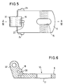
- Fig. 8 shows the cross-sectional shape of the leaf spring 12, the is designed essentially ⁇ -shaped and with their free Ends adapted to the radius of curvature of the projections 14, 16 is.
- leaf spring arrangement 10 shows a leaf spring arrangement with two leaf springs 12a, 12b, the one another in terms of their dimensions are coordinated that they are put on top of each other can be and together on the cam-like projections 14, 16 of the single-axis hinge can be clamped can.
- Such a leaf spring arrangement with two leaf springs 12a, 12b has the advantage of being on the individual To reduce leaf spring acting tensile and compressive stresses which increases the service life of the leaf spring can.
- FIG. 11 shows a further leaf spring arrangement with two Leaf springs 12a, 12b, in which the outer leaf spring 12a inner leaf spring 12b does not completely enclose.
- a such leaf spring is cheaper to manufacture and easier to assemble.
Landscapes
- Engineering & Computer Science (AREA)
- Mechanical Engineering (AREA)
- Hinges (AREA)
- Glass Compositions (AREA)
- Closing And Opening Devices For Wings, And Checks For Wings (AREA)
- Dry Shavers And Clippers (AREA)
- Piezo-Electric Or Mechanical Vibrators, Or Delay Or Filter Circuits (AREA)
- Transition And Organic Metals Composition Catalysts For Addition Polymerization (AREA)
- Hinge Accessories (AREA)
- Extensible Doors And Revolving Doors (AREA)
Claims (12)
- Charnière à un seul axe, en particulier pour portes repliables (2) à plusieurs battants (3), comportant au moins deux pattes de charnière (4, 6) reliées l'une à l'autre de manière articulée par une articulation à un seul axe (5), et des pièces de charnière en forme de pots (8, 10) aptes à être fixées dans les battants de porte (3), pièces dans lesquelles les pattes de charnière (4, 6) , chacune avec une partie en forme de plaque, sont fixées de manière réglable, et comportant un ressort (12) qui maintient dans un premier état stable sous précontrainte les deux pattes de charnière (4, 6) dans une position de fermeture des battants (3) sous un angle mutuel de 180°, relativement à la position déployée s'étendant dans un plan des deux pattes de charnière (4, 6) et des deux battants reliés par la charnière, et qui les maintient dans un deuxième état stable, dans une position d'ouverture avec un écart, sous un angle mutuel d'environ 0°,
caractérisée par le fait que l'axe de rotation de l'articulation à un seul axe (5) est disposé, relativement à la zone d'articulation des pattes de charnière (4, 6), à distance des parties en forme de plaque, et que le ressort (12), relativement à la zone d'articulation des pattes de charnière (4, 6), attaque les pattes de charnière du côté des pattes de charnière (4, 6) tourné vers l'axe de rotation. - Charnière à un seul axe selon la revendication 1, caractérisée par le fait que le ressort (12) presse les deux pattes de charnière (4, 6) contre une butée limitant l'angle d'ouverture à 180°.
- Charnière à un seul axe selon l'une des revendications 1 ou 2, caractérisée par le fait que le ressort (12) maintient les deux pattes de charnière (4, 6) dans un deuxième état stable, dans une position d'ouverture des battants (3) sous un angle mutuel d'environ 0°.
- Charnière à un seul axe selon l'une des revendications 1 à 3, caractérisée par le fait que l'axe de rotation de l'articulation à un seul axe (5) est disposé, relativement à la zone d'articulation des pattes de charnières (4, 6), du côté intérieur des pattes de charnière (4, 6).
- Charnière à un seul axe selon l'une des revendications 1 à 4, caractérisée par le fait que le ressort (12) est disposé, relativement à la zone d'articulation des pattes de charnière (4, 6), du côté intérieur des pattes de charnière (4, 6).
- Charnière à un seul axe selon l'une des revendications 1 à 5, caractérisée par le fait que le ressort (12) est constitué d'un arrangement de ressort à lame avec au moins un ressort à lame (12, 12a, 12b), qui vient en prise derrière les deux pattes de charnière (4, 6) avec respectivement au moins une saillie (14, 16).
- Charnière à un seul axe selon la revendication 6, caractérisée par le fait que les saillies (14, 16) sur les pattes de charnière (4, 6) sont déterminées respectivement par une rainure (18, 20) s'étendant parallèlement à l'axe de rotation de l'articulation à un seul axe (5).
- Charnière à un seul axe selon la revendication 7, caractérisée par le fait que la rainure (18, 20) est interrompue par au moins une nervure de raidissement (22).
- Charnière à un seul axe selon l'une des revendications 1 à 8, caractérisée par le fait que les pattes de charnière (4, 6) comportent des saillies latérales (24) disposées au voisinage de l'axe de rotation de l'articulation à un seul axe (5), qui s'accrochent dans les pièces de charnière en forme de pots (8, 10).
- Charnière à un seul axe selon revendication 1 à 9, caractérisée par le fait que les pattes de charnière (4, 6), ainsi que les pièces de charnière en forme de pots (8, 10) recevant les pattes de charnière (4, 6), comportent des surfaces dentées (17, 19) adaptées les unes aux autres et tournées les unes vers les autres, lesquelles surfaces dentées sont mutuellement en prise.
- Charnière à un seul axe selon l'une des revendications 6 à 10, caractérisée par le fait que l'arrangement de ressort à lame se compose de deux ressorts à lame, un ressort à lame extérieur (12a) étant placé sur un ressort à lame intérieur (12b) avec au moins partiellement une liaison positive.
- Charnière à un seul axe selon l'une des revendications 1 à 11, caractérisée par le fait que, sur les pièces de charnière en forme de pots (8, 10), sur la face frontale tournée vers la fente (9) entre les battants (3), est disposée une rainure (25) pour le logement d'une garniture (26) extensible suivant la fente (9).
Applications Claiming Priority (3)
| Application Number | Priority Date | Filing Date | Title |
|---|---|---|---|
| DE29500886U DE29500886U1 (de) | 1995-01-20 | 1995-01-20 | Einachsscharnier |
| DE29500886U | 1995-01-20 | ||
| PCT/EP1996/000114 WO1996022441A1 (fr) | 1995-01-20 | 1996-01-12 | Charniere a un seul axe |
Publications (2)
| Publication Number | Publication Date |
|---|---|
| EP0804671A1 EP0804671A1 (fr) | 1997-11-05 |
| EP0804671B1 true EP0804671B1 (fr) | 1998-12-02 |
Family
ID=8002747
Family Applications (1)
| Application Number | Title | Priority Date | Filing Date |
|---|---|---|---|
| EP96900317A Expired - Lifetime EP0804671B1 (fr) | 1995-01-20 | 1996-01-12 | Charniere a un seul axe |
Country Status (4)
| Country | Link |
|---|---|
| EP (1) | EP0804671B1 (fr) |
| AT (1) | ATE174099T1 (fr) |
| DE (2) | DE29500886U1 (fr) |
| WO (1) | WO1996022441A1 (fr) |
Families Citing this family (3)
| Publication number | Priority date | Publication date | Assignee | Title |
|---|---|---|---|---|
| IT1292005B1 (it) * | 1997-05-27 | 1999-01-25 | Aldo Mignani | Dispositivo di collegamento a cerniera in particolare per ante di armadi |
| ES2166255B1 (es) * | 1999-04-13 | 2003-01-01 | Imaginacion Organizada S L | Bisagra plana para puerta plegable. |
| DE102011115536A1 (de) * | 2011-08-17 | 2013-02-21 | Weinor Gmbh & Co. Kg | Schiebefalttürsystem |
Family Cites Families (6)
| Publication number | Priority date | Publication date | Assignee | Title |
|---|---|---|---|---|
| DE2952246A1 (de) * | 1979-12-24 | 1981-07-30 | Hetal-Werke Franz Hettich Gmbh & Co, 7297 Alpirsbach | Moebelscharnier |
| DE3104275A1 (de) * | 1981-02-07 | 1982-08-19 | Huwil-Werke GmbH Möbelschloß- und Beschlagfabriken, 5207 Ruppichteroth | Scharnier, insbesondere fuer falttueren |
| GB2137691B (en) * | 1983-01-24 | 1986-07-16 | Dantville Limited | Folding element |
| JPH022978U (fr) * | 1988-06-10 | 1990-01-10 | ||
| DE9105891U1 (fr) * | 1991-05-13 | 1991-08-14 | Bockisch, Karlheinz, 3008 Garbsen, De | |
| DE4035199C2 (de) * | 1990-11-06 | 2001-05-31 | Lautenschlaeger Mepla Werke | Eingelenk-Möbelscharnier |
-
1995
- 1995-01-20 DE DE29500886U patent/DE29500886U1/de not_active Expired - Lifetime
-
1996
- 1996-01-12 AT AT96900317T patent/ATE174099T1/de not_active IP Right Cessation
- 1996-01-12 WO PCT/EP1996/000114 patent/WO1996022441A1/fr active IP Right Grant
- 1996-01-12 EP EP96900317A patent/EP0804671B1/fr not_active Expired - Lifetime
- 1996-01-12 DE DE59600909T patent/DE59600909D1/de not_active Expired - Lifetime
Also Published As
| Publication number | Publication date |
|---|---|
| WO1996022441A1 (fr) | 1996-07-25 |
| DE29500886U1 (de) | 1995-03-02 |
| DE59600909D1 (de) | 1999-01-14 |
| EP0804671A1 (fr) | 1997-11-05 |
| ATE174099T1 (de) | 1998-12-15 |
Similar Documents
| Publication | Publication Date | Title |
|---|---|---|
| DE4219681C2 (de) | Einstellbares Abhebescharnier | |
| EP0598364B1 (fr) | Charnière pour portes, fenêtres ou similaire | |
| EP1331339B1 (fr) | Charnière pour portes, fenêtres et similaires | |
| DE2653106C2 (de) | Klappenhalter | |
| EP0804671B1 (fr) | Charniere a un seul axe | |
| DE202010016815U1 (de) | Ein Band, vorzugsweise für Türen | |
| WO1990015911A1 (fr) | Charniere | |
| EP0468176B1 (fr) | Charnière pour la jonction articulée des deux ailes d'une porte pliante | |
| DE4341422C2 (de) | Topfscharnier | |
| DE102012104863B3 (de) | Türbandanordnung mit einem Türband und einem Aufnahmeelement | |
| DE2443036C3 (de) | Ausstellvorrichtung | |
| EP0931897A1 (fr) | Charnière à arrêt de porte intégré | |
| EP0019841B1 (fr) | Porte oscillante à ferme-porte actionné par un ressort | |
| DE102022204028B3 (de) | Scharnierband für eine Gebäudetür oder ein Gebäudefenster | |
| EP3623558B1 (fr) | Ferrure de couvercle destinée à la fixation pivotante d'un couvercle à un corps de meuble | |
| WO2004038145A1 (fr) | Charniere | |
| EP1245771B1 (fr) | Charnière pour portes ou fenêtres | |
| DE3120065A1 (de) | Moebelscharnier | |
| DE102005015541B4 (de) | Kraftfahrzeugscharnier für Türen und Klappen | |
| DE2660245C2 (de) | Scharnier zum gelenkigen Verbinden zweier Bauteile | |
| DE202007002494U1 (de) | Gelenkband für Türen und Fenster | |
| EP3073039A1 (fr) | Disposition de la fiche articulee | |
| DE102005000706B4 (de) | Vorrichtung zur Anordnung einer Falttür an einer von der Falttür zu verschließenden Öffnung eines Möbels oder einer Öffnung einer Wand | |
| EP0450626A1 (fr) | Charnière en deux parties pour un battant, de préférence de meuble | |
| DE2131852B2 (de) | Klappenscharnier |
Legal Events
| Date | Code | Title | Description |
|---|---|---|---|
| PUAI | Public reference made under article 153(3) epc to a published international application that has entered the european phase |
Free format text: ORIGINAL CODE: 0009012 |
|
| 17P | Request for examination filed |
Effective date: 19970704 |
|
| AK | Designated contracting states |
Kind code of ref document: A1 Designated state(s): AT DE IT |
|
| GRAG | Despatch of communication of intention to grant |
Free format text: ORIGINAL CODE: EPIDOS AGRA |
|
| GRAG | Despatch of communication of intention to grant |
Free format text: ORIGINAL CODE: EPIDOS AGRA |
|
| 17Q | First examination report despatched |
Effective date: 19980120 |
|
| GRAG | Despatch of communication of intention to grant |
Free format text: ORIGINAL CODE: EPIDOS AGRA |
|
| GRAH | Despatch of communication of intention to grant a patent |
Free format text: ORIGINAL CODE: EPIDOS IGRA |
|
| GRAH | Despatch of communication of intention to grant a patent |
Free format text: ORIGINAL CODE: EPIDOS IGRA |
|
| GRAA | (expected) grant |
Free format text: ORIGINAL CODE: 0009210 |
|
| AK | Designated contracting states |
Kind code of ref document: B1 Designated state(s): AT DE IT |
|
| REF | Corresponds to: |
Ref document number: 174099 Country of ref document: AT Date of ref document: 19981215 Kind code of ref document: T |
|
| REF | Corresponds to: |
Ref document number: 59600909 Country of ref document: DE Date of ref document: 19990114 |
|
| ITF | It: translation for a ep patent filed |
Owner name: PORTA CHECCACCI E BOTTI S.R.L. |
|
| PLBE | No opposition filed within time limit |
Free format text: ORIGINAL CODE: 0009261 |
|
| STAA | Information on the status of an ep patent application or granted ep patent |
Free format text: STATUS: NO OPPOSITION FILED WITHIN TIME LIMIT |
|
| 26N | No opposition filed | ||
| PGFP | Annual fee paid to national office [announced via postgrant information from national office to epo] |
Ref country code: IT Payment date: 20100123 Year of fee payment: 15 |
|
| PGFP | Annual fee paid to national office [announced via postgrant information from national office to epo] |
Ref country code: AT Payment date: 20100120 Year of fee payment: 15 |
|
| PG25 | Lapsed in a contracting state [announced via postgrant information from national office to epo] |
Ref country code: AT Free format text: LAPSE BECAUSE OF NON-PAYMENT OF DUE FEES Effective date: 20110112 |
|
| PG25 | Lapsed in a contracting state [announced via postgrant information from national office to epo] |
Ref country code: IT Free format text: LAPSE BECAUSE OF NON-PAYMENT OF DUE FEES Effective date: 20110112 |
|
| PGFP | Annual fee paid to national office [announced via postgrant information from national office to epo] |
Ref country code: DE Payment date: 20140325 Year of fee payment: 19 |
|
| REG | Reference to a national code |
Ref country code: DE Ref legal event code: R119 Ref document number: 59600909 Country of ref document: DE |
|
| PG25 | Lapsed in a contracting state [announced via postgrant information from national office to epo] |
Ref country code: DE Free format text: LAPSE BECAUSE OF NON-PAYMENT OF DUE FEES Effective date: 20150801 |