EP1149664B1 - Cup attaching apparatus - Google Patents
Cup attaching apparatus Download PDFInfo
- Publication number
- EP1149664B1 EP1149664B1 EP01110463A EP01110463A EP1149664B1 EP 1149664 B1 EP1149664 B1 EP 1149664B1 EP 01110463 A EP01110463 A EP 01110463A EP 01110463 A EP01110463 A EP 01110463A EP 1149664 B1 EP1149664 B1 EP 1149664B1
- Authority
- EP
- European Patent Office
- Prior art keywords
- lens
- cup
- display
- alignment mark
- mark
- Prior art date
- Legal status (The legal status is an assumption and is not a legal conclusion. Google has not performed a legal analysis and makes no representation as to the accuracy of the status listed.)
- Expired - Lifetime
Links
- 230000003287 optical effect Effects 0.000 claims description 41
- 238000012545 processing Methods 0.000 claims description 36
- 230000000750 progressive effect Effects 0.000 claims description 23
- 238000003384 imaging method Methods 0.000 claims description 8
- 238000007493 shaping process Methods 0.000 claims description 2
- 238000010586 diagram Methods 0.000 description 13
- 238000000034 method Methods 0.000 description 5
- 238000012790 confirmation Methods 0.000 description 4
- 238000006073 displacement reaction Methods 0.000 description 4
- 230000000694 effects Effects 0.000 description 3
- 239000011295 pitch Substances 0.000 description 3
- 239000011521 glass Substances 0.000 description 2
- 238000005286 illumination Methods 0.000 description 2
- 239000000463 material Substances 0.000 description 2
- 230000001179 pupillary effect Effects 0.000 description 2
- 239000004820 Pressure-sensitive adhesive Substances 0.000 description 1
- NIXOWILDQLNWCW-UHFFFAOYSA-N acrylic acid group Chemical group C(C=C)(=O)O NIXOWILDQLNWCW-UHFFFAOYSA-N 0.000 description 1
- 201000009310 astigmatism Diseases 0.000 description 1
- 238000004891 communication Methods 0.000 description 1
- 238000012937 correction Methods 0.000 description 1
- 238000005530 etching Methods 0.000 description 1
- 239000004973 liquid crystal related substance Substances 0.000 description 1
- 239000002184 metal Substances 0.000 description 1
- 230000002093 peripheral effect Effects 0.000 description 1
- 230000002194 synthesizing effect Effects 0.000 description 1
- 238000012546 transfer Methods 0.000 description 1
- 230000009466 transformation Effects 0.000 description 1
- 238000002834 transmittance Methods 0.000 description 1
Images


Classifications
-
- B—PERFORMING OPERATIONS; TRANSPORTING
- B24—GRINDING; POLISHING
- B24B—MACHINES, DEVICES, OR PROCESSES FOR GRINDING OR POLISHING; DRESSING OR CONDITIONING OF ABRADING SURFACES; FEEDING OF GRINDING, POLISHING, OR LAPPING AGENTS
- B24B13/00—Machines or devices designed for grinding or polishing optical surfaces on lenses or surfaces of similar shape on other work; Accessories therefor
- B24B13/005—Blocking means, chucks or the like; Alignment devices
- B24B13/0055—Positioning of lenses; Marking of lenses
Definitions
- the present invention relates to a cup attaching apparatus for attaching a cup (a processing jig such as a suction cup, a leap cup which is attached through a pressure sensitive adhesive sheet, or the like) to a lens to be processed (subject lens), which cup is used at the time of processing a peripheral edge of an eyeglass lens, (see for example EP-A-0 933 163).
- a processing jig such as a suction cup, a leap cup which is attached through a pressure sensitive adhesive sheet, or the like
- a lens to be processed subject lens
- a cup attaching apparatus of this type is designed such that a scale plate provided with a scale as well as a subject lens are illuminated, an image of the scale and an image of a mark point provided on the subject lens by a lens meter or the like are formed on a screen, and the scale image and mark point image are observed so as to effect alignment for attaching the cup.
- an image of its small lens portion is formed on the screen, while, in the case of a progressive multifocal lens, an image of a layout mark or a hidden mark (marked in advance) printed on the lens surface is formed on the screen, and the alignment is effected on the basis of the image of the small lens portion or the mark and the image of the scale.
- the kinds of lenses are diverse, and the cup attaching position for a bifocal lens and a progressive multifocal lens, in particular, differ depending on the lenses, it has not been easy to attach the cup to the lens with high accuracy by the alignment using the scale plate.
- the present invention provides a cup attaching apparatus having the following features.
- Fig. 1 is an external view of the apparatus
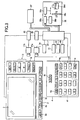
- Fig. 2 is a schematic diagram of an optical system provided in the apparatus.
- Reference numeral 1 denotes an apparatus main body having substantially U-shaped side surfaces, and an illuminating optical system and an imaging optical system shown in Fig. 2 are disposed therein.
- a color monitor 2 such as a liquid-crystal display and an upper switch panel 3 are provided on an upper front surface of the main body 1, and a lower switch panel 4 is provided on a lower front surface.
- Displayed on the monitor 2 are an image of a subject lens LE which is imaged by a second CCD camera 17b, various marks for alignment, a layout screen (including input items for layout), and the like (described later).
- Numeral 5 denotes a circular lens table of transparent acrylic material, which is set on a base 1a of the main body 1 by a table support portion 6.
- An index portion 12 on which a prescribed pattern is provided is formed on a center of the table 5.
- Provided on the index portion 12 in this embodiment are a plurality of dot indexes arranged into a grid shape, which are formed by etching an upper surface of the table 5.
- the dot indexes, each having 0.3mm in diameter are provided at 0.3mm pitches in an square area of 20mm x 20mm about the reference axis L that is a center for the cup attachment (see Fig. 4).
- the index portion 12 may be disposed on the illumination light source side with respect to the lens LE.
- Numeral 7 denotes a lens attaching portion for attaching a cup 19, i.e., a processing jig, to the lens LE.
- the cup attaching portion 7 includes a shaft 7a which is rotated by a motor 31 and moved vertically by a motor 32, and an arm 7b fixed to the shaft 7a.
- the motors 31 and 32 are provided inside the main body 1.
- An attaching portion 7c for fitting a proximal portion of the cup 19 is provided on the underside of a distal end of the arm 7b.
- the cup 19 is attached in a predetermined direction in accordance with a positioning mark provided on an upper surface of the arm 7b.
- a mechanism for moving the cup attaching portion 7 may be so arranged that the shaft 7a is moved horizontally (linearly) in stead of being rotated used in this embodiment. Further, the shaft 7a may project not from the lower side of the main body 1, but from the upper side thereof.
- numeral 10 denotes an illuminating light source
- 11 denotes a collimator lens.
- An optical axis of the collimator lens 11 is substantially coincident with the reference axis L, and an illumination light source 10 is located at or around a focal point of the lens 11 in the rear side.
- the illuminating light from the light source 10 is converted into substantially parallel rays of light having a larger diameter than that of the lens LE by means of the collimator lens 11, and is then projected onto the lens LE placed on the table 5.
- the light is transmitted through the lens LE and illuminates the index portion 12 on the table 5, so that an overall image of the lens LE and dot index images (i.e. images of dot indexes) subjected to the prismatic action of the lens LE are projected onto the screen plate 13.
- a half mirror 15 is disposed below the screen plate 13, and a first CCD camera 17a is provided on the reference axis L in the direction of its transmittance. This first camera 17a is disposed so as to be able to image in enlarged form only a central region with the reference axis L set as a center for the cup attachment so that the dot index images formed on the screen plate 13 can be detected.
- a mirror 16 and a second CCD camera 17b for imaging an image reflected by the mirror 16 are disposed in the reflecting direction of the half mirror 15.
- This second camera 17b is disposed so as to be able to image the substantially entire screen plate 13 so that the overall image of the lens LE projected onto the screen plate 13 can be obtained.
- Fig. 3 is a block diagram illustrating a controlling system of the apparatus.
- An image signal from the first camera 17a is inputted to an image processing unit 34.
- the processing unit 34 effects image processing to detect the position of each dot index image, and inputs the detected signal to a control unit 30.
- the control unit 30 determines the position of the optical center of the lens LE and the direction (angle) of the cylinder axis (astigmatism axis) (which will be described later).
- an image signal from the second camera 17b is inputted to an image synthesizing circuit 35, and the circuit 35 combines the image of the lens LE with characters, marks and so on generated by a display circuit 36 connected to the control unit 30, and displays the same on the monitor 2.
- the motor 31 for rotating the shaft 7a the motor 32 for vertically moving the shaft 7a
- a memory 40 for storing the inputted data and the like the switch panels 3 and 4
- a target lens shape measuring device 37 for measuring a target lens shape of an eyeglasses frame, a template, a dummy lens or the like the lens processing apparatus 38 for grinding the lens LE.
- the processing unit 34 determines the coordinate positions of the dot index images, and stores the same in advance.
- the position of the dot index image located immediately below the vicinity of the optical center of the lens LE remains the same irrespective of the presence or absence of the lens LE, but the coordinate positions of the dot index images located at portions which are not at the optical center are changed due to the prismatic action of the lens LE.
- a change in the coordinate position of each dot index image with the lens LE mounted with respect to the coordinate position of each dot index image with the lens LE not mounted is examined, and a center position where the dot index images diverge from or converge toward is determined.
- the center position of this divergence or convergence can be detected as the position of the optical center.
- dot index images P 1 with the lens LE not mounted converge (move) with a dot index image P 0 as the center to become dot index images P 2 .
- the coordinate position of the dot index image P 0 can be detected as the position of the optical center.
- the optical center is located between dot indexes, it suffices if the optical center is determined by interpolating the center of movement on the basis of the moving directions of the dot index images and the amounts of theirmovement.
- the dot index images move in a direction toward (or away from) a generating line of the lens LE.
- the direction of the cylinder axis can be similarly detected by examining in which direction the dot index images are moving with respect to the coordinate positions of the dot index images with the lens LE not mounted.
- the target lens shape of the eyeglasses frame into which the lens LE is fitted (or the target lens shape of the template or the dummy lens) is measured in advance by the measuring device 37 connected to the main body 1 .
- a TRACE key 3j is pressed, data on the target lens shape (traced outline) is inputted.
- the inputted target lens shape (traced outline) data is stored in the memory 40, and an target lens shape (traced outline) figure 20 based on the inputted target lens shape (traced outline) data is displayed on the monitor 2 (See Fig. 5).
- the type of the lens i.e., a monofocal, biforcal or progressive multifocal lens
- TYPE key 3b is selected by a TYPE key 3b.
- the cursor 21 is moved to the item AXIS, and the cylinder axis angle (direction) in the prescription is inputted in advance (or the angle of the cylinder (astigmatic) axis is set to 180° or 90°).
- the layout data may be transferred to the lens processing apparatus (lens edger) 38, and the type of the lens LE (such as plastic or glass) and the type of the eyeglasses frame (such as metal or cell) may be inputted in advance by a LENS key 3a, a FRAME key 3c, and the like for convenience sake, so that processing can be performed smoothly by using the layout data.
- the frame shape data (three-dimensional data) is transferred and inputted to the lens processing apparatus (lens edger) 38.
- a cup figure 23a indicating the shape of the cup 19 to be attached to the lens LE is displayed in red color on the screen of the monitor 2 (see Fig. 5) by using as the center the position on the screen corresponding to the reference axis L which is the center of cup attachment.
- the data on the shape of the cup 19 for displaying the cup figure 23a is stored in advance in the memory 40.
- the target lens shape (traced outline) figure 20 is displayed in such a state that the layout optical center (eyepoint position) is aligned with the center of the cup figure 23a.
- an AXIS mark 24 inclined in the direction of that angle is displayed in red color.
- the operator places the lens LE on the table 5, and performs alignment for attaching the cup 19. If the center of the lens LE is made to be located in the vicinity of the center of the table 5 (such that the position of the optical center of the lens LE is located within the index portion 12), an image of the lens LE and images of the dot indexes on the index portion 12 are formed on the screen plate 13.
- the second camera 17b picks up an entire image of the lens LE, and its picked-up image LE' is displayed on the screen of the monitor 2 (see Fig. 6).
- the dot index images formed on the screen plate 13 are picked up by the first camera 17a.
- the image signal is inputted to the processing unit 34, and the control unit 30 executes the aforementioned method to continuously obtain information on the displacement (offset) of the position of the optical center from the reference axis L and information on the direction of the cylinder axis on the basis of information on the coordinate positions of dot index images detected by the image processing unit 34.
- a cross mark 25 indicating the position of the optical center of the lens LE is displayed in white color by the display circuit 36 which is controlled by the control unit 30, as shown in Fig. 6.
- This cross mark 25 is displayed such that the center of a circle “O" depicted in the center conforms to the detected position of the optical center of the lens LE, and such that the long axis of the cross mark 25 is inclined to conform to the information on the direction of the cylinder axis detected.
- the red ASIX mark 24 indicating the angle (direction) of the cylinder (astigmatic) axis inputted is displayed with the center of the cross mark 25 (the position of the optical center of the lens LE) as a reference.
- the target lens shape (traced outline) figure 20 is displayed such that the position of the layout optical center (eyepoint position) is aligned with the detected position of the optical center of the lens LE, and such that the inputted angle (direction) of the cylinder (astigmatic) axis conforms to the detected direction of the cylinder axis of the lens LE. Further, since this target lens shape (traced outline) figure 20 is displayed by being superposed on the lens image LE', by observing the two images at this stage the operator is able to instantly determine whether or not the lens diameter is insufficient for processing.
- the alignment operation for attaching the cup 19 at the position of the optical center of the lens LE is performed as follows. Since a reference mark 22 serving as a target for positioning is displayed in red color at the center of the cup figure 23a on the screen, the operator moves the lens LE so that the center of the reference mark 22 and the center of the cross mark 25 are aligned, thereby effecting the alignment of the position of the optical center of the lens LE with respect to the reference axis L. As for the alignment of the direction of the cylinder axis, the lens LE is rotated so that the long axis of the cross mark 25 conforms to the direction of the AXIS mark 24.
- the alignment of the direction of the cylinder axis canbe concurrently effected while performing the alignment of the position of the optical center.
- the alignment of the position of the optical center can be effected after substantially completing the alignment of the direction of the cylinder axis, the degree of offset of the center accompanying the rotational movement of the lens LE is reduced, so that the efficiency in the alignment operation can be achieved.
- the white cross mark 25 is superposed on the AXIS mark 24, and the display of the red AXIS mark 24 disappears.
- the display of the reference mark 22 disappears such that the reference mark 22 is hidden by the circle "0" depicted in the center of the cross mark 25. Then, upon completion of the alignment of both the direction of the cylinder axis and the position of the optical center, the color of the cup figure 23a changes from red to blue.
- the operator is able to ascertain the completion of alignment.
- the cup figure 23a is accommodated within the target lens shape (tranced outline) figure 20, it is possible to confirm that no processing interference will occur at the time of processing by the lens processing apparatus (lens edger) 38.
- the operator Upon completion of the alignment of the position of the optical center of the lens LE and the direction of the cylinder axis, the operator presses a BLOCK key 4k for instructing the cup attachment.
- the control unit 30 drives the motor 31 to rotate the shaft 7a so as to allow the cup 19 to arrive at the reference axis L, then drives the motor 32 to lower the cup 19 and allows the lens LE to be fixed by the cup 19.
- the cup 19 may be attached to an arbitrary position, and information on that attached position maybe usedas correction information for coordinate transformation at the time of processing by the lens processing apparatus (lens edger) 38.
- the lens processing apparatus lens processing apparatus
- the target lens shape (tracedoutline) figure 20 is displayed in correspondence with the detected angle (direction) of the cylinder axis (i.e., it is displayed by being inclined in correspondence with the amount of offset of the angle of the cylinder axis), if confirmation is made that the cup figure 23a can be accommodated within the target lens shape (traced outline) figure 20, it is possible to attach the cup 19 at the position where processing interference can be avoided.
- the JOB number is inputted in advance by operating the key 4a and the key 4f, so that the target lens shape (traced outline) data, the layout data, the information on the displacement (offset) of the position of the optical center, the information on the displacement (offset) of the direction of the cylinder axis, and the like which are stored in the memory 40 can be managed by the JOB number.
- a bifocal lens mode is selected by the key 3b.
- a small lens mark 50 which simulates the small lens portion of the bifocal lens, is displayed on the screen of the monitor 2 at a position which is offset by a preset amount of deviation with respect to the reference mark 22 indicating the center of cup attachment. Further, three vertical line marks 51L, 51R at 2 mm intervals are displayed at each of left and right ends of the small lens mark 50.
- An upper boundary center 50a of the small lens mark 50 serves as a reference for aligning the small lens portion of the lens LE, while the vertical line marks 51L and 51R serve as guides for the left-right distribution in alignment.
- a plurality of horizontal line marks 52 are displayed at 1-mm pitch intervals by using the cup attachment center (reference mark 22) as a reference, and these horizontal line marks 52 serve as guides for horizontally aligning the small lens portion. It shouldbe noted that the horizontal line marks 52 maybe displayed by using the small lens mark 50 as a reference.
- Input items for the layout of the lens LE are displayed on the left-hand side of the screen of the monitor 2.
- the pupillary distance for the near use is entered in an item 55a, while the distance from the upper boundary center of the small lens portion to the bottom of the target lens shape (traced outline) directly below the upper boundary center is entered in an item 55b.
- the display position of the target lens shape (traced outline) figure 20 is determined, thereby completing the layout of the lens LE with respect to the target lens shape (traced outline) data.
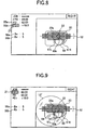
- Fig. 8 is an example in which the right lens has been selected by the key 4g.
- the display positions of the small lens mark 50 and the vertical line marks 51L and 51R are changed to bilaterally inverted positions about the reference mark 22.
- the positioning of the bifocal lens is carried out as follows. If the lens (bifocal lens) LE is placed on the table 5, a small lens image of the lens LE illuminated by parallel rays of light is formed clearly on the screen plate 13. This image is picked up by the second camera 17b, and the lens image LE' and a small lens image 58 are displayed on the monitor 2, as shown in Fig. 9. The operator moves the lens LE such that the upper boundary center of the small lens image 58 is superposed on the upper boundary center 50a of the small lens mark 50.
- the alignment of the upper boundary center can be effected easily by uniformly distributing the left and right portions of the small lens image 58 by using as guides the vertical line marks 51L and 51R displayed symmetrically on the left- and right-hand sides of the small lens mark 50.
- the alignment is made in conformity with the horizontal line marks 52 so that the horizontal axis of the small lens image 58 will not be tilted.
- the position of attachment of the cup 19 with respect to the small lens portion is not fixed, and differs depending on the policy of a processor (eyeglasses shop) or a lens manufacturer.
- this apparatus is designed so that the display position (layout) of the small lens mark 50 can be changed arbitrarily.
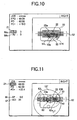
- the display position of the small lens mark 50 can be changed by changing values of a BX item 56a and a BY item 56b.
- the item 56a indicates the distance (mm) of offsetting the cup attaching position upwardly from the upper boundary center of the small lens
- the item 56b indicates the distance (mm) of offsetting the cup attaching position outwardly from the upper boundary center of the small lens.
- the display position of the small lens mark 50 in the horizontal and vertical directions with respect to the reference mark 22 on the monitor 2 is changed.
- the display positions of the vertical line marks 51L and 51R are moved in linking with the change of the display position of the small lens mark 50 (see Fig. 10).
- the display positions of the horizontal line marks 52 are also moved.
- the display on the monitor 2 is controlled via the display circuit 36 by the control unit 30.
- the lens LE is aligned while confirming the position of the small lens image 58 with respect to the small lens mark 50, the vertical line marks 51L and 51R, and the horizontal line marks 52 in the same way as described above.
- the main body 1 and the lens processing apparatus (lens edger) 38 are connected in such a manner as to be capable of effecting data communication, it is possible to transfer and input the data stored in the memory 40 to the processing apparatus 38 side by designating the JOB number.
- the processing apparatus 38 it is possible to use, for example, one disclosed in commonly assigned USP 5,716,256.
- the processing apparatus chucks the lens LE using two lens rotating shafts 38c and operates a moving mechanism 38e, which changes the axis-to-axis distance between the abrasive wheel rotating shaft of an abrasive wheel 38d and the lens rotating shafts 38c, thereby processing the lens LE based on the inputted data.
- the processing data are calculated on the processing apparatus 38 side on the basis of these data.
- the progressive multifocal lens mode is selected by the key 3b.
- the following procedure is taken in a case where the cup 19 is attached to the position of the eye point for far use by using a far-use eyepoint mark and a horizontal layout mark which are printed on the progressive multifocal lens. If the lens (progressive multifocal lens) LE is placed on the table 5, an image of the far-use eyepoint mark and an image of the horizontal layout mark, together with an image of the lens LE, are formed clearly on the screen plate 13, and these images are picked up by the second camera 17b, and are displayed on the monitor 2.
- Fig. 11 shows an example of the screen at this time, and the display position of the target lens shape (traced outline) figure 20 is determined by inputting in advance the layout data of the progressive multifocal lens in accordance with the input items being displayed on the left-hand side of the screen of the monitor 2.
- the operator observes a far-use eyepoint mark image 60 and a horizontal layout mark image 61, and moves the lens LE to align the far-use eyepoint mark image 60 with the reference mark 22.
- axis alignment can be made such that the horizontal layout mark image 61 is not tilted with respect to horizontal line marks 62, i.e., marks for alignment, which are displayed at 1-mm pitch intervals by using the cup attachment center (reference mark 22) as a reference.
- the cup 19 is attached to the far-use eyepoint position by using hidden marks on the progressive multifocal lens . Since two hidden marks are generally provided on the lens surface of the progressive multifocal lens, these hidden marks are confirmed and marks are respectively applied to these hidden marks with a pen or the like in advance.
- the distance (EP value) from the hidden mark on the lens LE to the far-use eyepoint height is inputted in advance in an EP item 66 shown in Fig. 12 as the layout data by the key 4f or the like in the same way as the above-described input of the layout data.
- the input can be made upon confirming the predetermined EP value.
- the display positions of the horizontal line marks 62 and a horizontal center frame mark 62a are displayed by being offset correspondingly to the input value with respect to the reference mark 22. In the example shown in Fig. 12, the display positions are offset 3.5mm downwardly.
- the lens (progressive multifocal lens) LE is placed on the table 5, as shown in Fig. 12, since two images 69 of the marks applied to the hidden marks are displayed on the monitor 2, the lens LE is moved such that the two mark images 69 are located within the horizontal center frame mark 62a.
- the left and right alignment marks three vertical line marks 63L at 2-mm intervals and three vertical line marks 63R are respectively displayed bilaterally symmetrically on the left-hand side and the right-hand side with the reference mark 22 or the horizontal line mark 62 as a reference. Therefore, alignment is made by using these vertical line marks, so that the two mark images 69 become bilaterally uniform.
- the interval between the vertical line marks 63L and the vertical line marks 63R can be varied by the distance value (WD value) of a layout item 67.
- the interval between the two hidden marks provided on the progressive multifocal lens differs depending on the lens manufacturers and the types of lenses. For this reason, the interval between the vertical line marks 63L and the vertical line marks 63R (i.e. between a central one of the marks 63L and a central one of the marks 63R) is changed in advance in conformity with the interval between the two hidden marks.
- the change of the WD value in the item 67 can be made by inputting a desired value by the keying operation of the switch panels 3 and 4 in the same way as the other items.
- the display positions of the vertical marks 63L and 63R are changed, so that the confirmation of the bilaterally uniform alignment of the two mark images 69 can be facilitated.
- the interval between the adjacent lines of the horizontal line marks 62 maybe made variable.
- the cup attachment can be effected with high accuracy and with ease.
Landscapes
- Engineering & Computer Science (AREA)
- Mechanical Engineering (AREA)
- Grinding And Polishing Of Tertiary Curved Surfaces And Surfaces With Complex Shapes (AREA)
- Eyeglasses (AREA)
- Liquid Crystal (AREA)
Applications Claiming Priority (2)
| Application Number | Priority Date | Filing Date | Title |
|---|---|---|---|
| JP2000134250 | 2000-04-28 | ||
| JP2000134250A JP3842953B2 (ja) | 2000-04-28 | 2000-04-28 | カップ取付け装置 |
Publications (3)
| Publication Number | Publication Date |
|---|---|
| EP1149664A2 EP1149664A2 (en) | 2001-10-31 |
| EP1149664A3 EP1149664A3 (en) | 2004-01-14 |
| EP1149664B1 true EP1149664B1 (en) | 2006-02-08 |
Family
ID=18642560
Family Applications (1)
| Application Number | Title | Priority Date | Filing Date |
|---|---|---|---|
| EP01110463A Expired - Lifetime EP1149664B1 (en) | 2000-04-28 | 2001-04-27 | Cup attaching apparatus |
Country Status (5)
| Country | Link |
|---|---|
| US (1) | US6599171B2 (enExample) |
| EP (1) | EP1149664B1 (enExample) |
| JP (1) | JP3842953B2 (enExample) |
| DE (1) | DE60117067T2 (enExample) |
| ES (1) | ES2258043T3 (enExample) |
Families Citing this family (14)
| Publication number | Priority date | Publication date | Assignee | Title |
|---|---|---|---|---|
| JP2002139713A (ja) | 2000-10-31 | 2002-05-17 | Hoya Corp | 眼鏡レンズのレンズホルダ取付方法及び装置 |
| US6837580B2 (en) * | 2001-10-26 | 2005-01-04 | Pentax Corporation | Progressive power lens |
| US7648237B2 (en) * | 2004-03-31 | 2010-01-19 | Topcon Corporation | Device for installing suction jig for eyeglass lens and method for determining suction jig installation position |
| JP4541017B2 (ja) * | 2004-03-31 | 2010-09-08 | 株式会社トプコン | レンズ吸着治具装着装置 |
| JP4756828B2 (ja) * | 2004-04-27 | 2011-08-24 | 株式会社ニデック | レンズメータ |
| FR2900246B1 (fr) * | 2006-04-20 | 2008-07-04 | Essilor Int | Procede de detection d'un referentiel optique d'une lentille ophtalmique |
| FR2983313B1 (fr) * | 2011-11-29 | 2014-06-27 | Essilor Int | Support de lentille ophtalmiquë pour dispositif de centrage |
| KR101352377B1 (ko) | 2012-01-20 | 2014-01-24 | 한국지질자원연구원 | 노두의 상태를 확인하기 위한 촬영장치 |
| JP6543464B2 (ja) * | 2014-12-26 | 2019-07-10 | ホヤ レンズ タイランド リミテッドHOYA Lens Thailand Ltd | 眼鏡レンズ |
| JP7087366B2 (ja) | 2017-12-05 | 2022-06-21 | 株式会社ニデック | 軸出し装置、眼鏡レンズ加工システム、及び眼鏡レンズ加工方法 |
| JP6710815B1 (ja) * | 2019-09-27 | 2020-06-17 | 株式会社レクザム | レンズ光学特性測定装置、レンズ光学特性測定方法、プログラム、及び、記録媒体 |
| EP3943240B1 (en) | 2020-07-24 | 2025-07-09 | Essilor International | Centering apparatus and process |
| USD1079949S1 (en) * | 2023-05-17 | 2025-06-17 | Essilor International | Lens tracer blocker for ophthalmic lenses or spectacle frames |
| US12134166B1 (en) * | 2024-05-30 | 2024-11-05 | GrayMatter Robotics Inc. | System and method for autonomously grinding a workpiece |
Family Cites Families (18)
| Publication number | Priority date | Publication date | Assignee | Title |
|---|---|---|---|---|
| DE1948644A1 (de) * | 1969-09-26 | 1971-04-01 | Zeiss Carl Fa | Vorrichtung zum Ausrichten einer rohkantigen Linse zur Formschablone ihrer Fassung |
| DE2220373A1 (de) * | 1972-04-26 | 1973-11-15 | Wernicke & Co Kg | Vorrichtung zum zentrieren von brillenglaesern, insbesondere von brillenglaesern mit nahteil, und zum anbringen eines halteteils auf dem brillenglas |
| FR2582975B1 (fr) * | 1985-06-10 | 1987-08-28 | Briot Int | Appareil pour centrer et poser un adaptateur sur une ebauche de verre optique et pour commander une rectifieuse |
| FR2607268B1 (fr) | 1986-11-26 | 1990-06-08 | Essilor Int | Appareil de centrage pour lentille ophtalmique |
| DE3829488A1 (de) | 1988-08-31 | 1990-03-01 | Wernicke & Co Gmbh | Vorrichtung zum zentrieren von brillenglaesern und aufbringen eines halteteils auf diesen sowie anwendung der vorrichtung |
| JP2801620B2 (ja) | 1988-10-05 | 1998-09-21 | 株式会社トプコン | レンズメータ |
| EP0363281B1 (en) | 1988-10-05 | 1997-05-28 | Kabushiki Kaisha TOPCON | Lens meter |
| ES2014801A6 (es) | 1989-07-17 | 1990-07-16 | Indo International S A | Aparato para el centrado y bloqueado de lentes oftalmologicas> |
| JPH03113415A (ja) | 1989-09-27 | 1991-05-14 | Topcon Corp | 軸出器 |
| US5155940A (en) | 1989-10-30 | 1992-10-20 | Kabushiki Kaisha Topcon | Apparatus for judging whether an uncut lens should be machined or not and lens grinding machine having the same |
| JP3011526B2 (ja) | 1992-02-04 | 2000-02-21 | 株式会社ニデック | レンズ周縁加工機及びレンズ周縁加工方法 |
| JP3113415B2 (ja) | 1992-09-25 | 2000-11-27 | ダイハツ工業株式会社 | 車載用撮像装置における画像処理方法 |
| JP4034842B2 (ja) | 1996-03-26 | 2008-01-16 | 株式会社ニデック | レンズ研削加工装置 |
| JP2786848B2 (ja) | 1997-02-07 | 1998-08-13 | 株式会社トプコン | 吸着済レンズの画像表示装置 |
| ES2136541B1 (es) | 1997-05-06 | 2000-08-01 | Indo Int Sa | Aparato para el centrado y bloqueo de un disco de lente oftalmica. |
| ES2230750T5 (es) | 1998-01-30 | 2012-05-21 | Nidek Co., Ltd. | Aparato para la sujeción de ventosas para lentes |
| JP3828686B2 (ja) * | 1999-08-31 | 2006-10-04 | 株式会社ニデック | カップ取付装置 |
| FR2799545B1 (fr) * | 1999-10-07 | 2002-01-18 | Briot Int | Procede et appareil de centrage d'une lentille ophtalmique |
-
2000
- 2000-04-28 JP JP2000134250A patent/JP3842953B2/ja not_active Expired - Lifetime
-
2001
- 2001-04-27 EP EP01110463A patent/EP1149664B1/en not_active Expired - Lifetime
- 2001-04-27 ES ES01110463T patent/ES2258043T3/es not_active Expired - Lifetime
- 2001-04-27 US US09/842,626 patent/US6599171B2/en not_active Expired - Lifetime
- 2001-04-27 DE DE60117067T patent/DE60117067T2/de not_active Expired - Lifetime
Also Published As
| Publication number | Publication date |
|---|---|
| US20010035937A1 (en) | 2001-11-01 |
| EP1149664A3 (en) | 2004-01-14 |
| US6599171B2 (en) | 2003-07-29 |
| DE60117067D1 (de) | 2006-04-20 |
| DE60117067T2 (de) | 2006-07-13 |
| JP2001311919A (ja) | 2001-11-09 |
| EP1149664A2 (en) | 2001-10-31 |
| ES2258043T3 (es) | 2006-08-16 |
| JP3842953B2 (ja) | 2006-11-08 |
Similar Documents
| Publication | Publication Date | Title |
|---|---|---|
| JP4746028B2 (ja) | 眼鏡レンズ用センタリング−ブロッキング装置、自動検出方法及び関連する手動センタリング方法 | |
| EP1149664B1 (en) | Cup attaching apparatus | |
| US6427094B1 (en) | Axial alignment apparatus, an eyeglass lens processing system and an eyeglass lens processing preparation system having the apparatus | |
| JP4970149B2 (ja) | カップ取付け装置 | |
| JP4068233B2 (ja) | カップ取付装置 | |
| KR101423768B1 (ko) | 안경 렌즈 가공 시스템 | |
| US6481095B1 (en) | Cup attaching apparatus | |
| US7527377B2 (en) | Method for manually centering an ophthalmic lens in a centering/blocking device and associated centering/blocking device | |
| US6798501B1 (en) | Cup attaching apparatus | |
| EP0933163B2 (en) | Cup attaching apparatus | |
| JPH11216650A (ja) | 軸出装置 | |
| JP4104297B2 (ja) | カップ取付け装置 | |
| US6298277B1 (en) | System for making an optical glass from a blank | |
| JPH0679600A (ja) | 眼鏡レンズの位置合わせ装置 | |
| JP3828685B2 (ja) | カップ取付装置 | |
| JPH09248746A (ja) | 軸打機 | |
| JP3007100B2 (ja) | フレームデータ表示装置 | |
| JPH09117850A (ja) | 画像表示装置 |
Legal Events
| Date | Code | Title | Description |
|---|---|---|---|
| PUAI | Public reference made under article 153(3) epc to a published international application that has entered the european phase |
Free format text: ORIGINAL CODE: 0009012 |
|
| AK | Designated contracting states |
Kind code of ref document: A2 Designated state(s): AT BE CH CY DE DK ES FI FR GB GR IE IT LI LU MC NL PT SE TR |
|
| AX | Request for extension of the european patent |
Free format text: AL;LT;LV;MK;RO;SI |
|
| PUAL | Search report despatched |
Free format text: ORIGINAL CODE: 0009013 |
|
| AK | Designated contracting states |
Kind code of ref document: A3 Designated state(s): AT BE CH CY DE DK ES FI FR GB GR IE IT LI LU MC NL PT SE TR |
|
| AX | Request for extension of the european patent |
Extension state: AL LT LV MK RO SI |
|
| 17P | Request for examination filed |
Effective date: 20040528 |
|
| AKX | Designation fees paid |
Designated state(s): DE ES FR GB |
|
| GRAP | Despatch of communication of intention to grant a patent |
Free format text: ORIGINAL CODE: EPIDOSNIGR1 |
|
| GRAS | Grant fee paid |
Free format text: ORIGINAL CODE: EPIDOSNIGR3 |
|
| GRAA | (expected) grant |
Free format text: ORIGINAL CODE: 0009210 |
|
| AK | Designated contracting states |
Kind code of ref document: B1 Designated state(s): DE ES FR GB |
|
| REG | Reference to a national code |
Ref country code: GB Ref legal event code: FG4D |
|
| REF | Corresponds to: |
Ref document number: 60117067 Country of ref document: DE Date of ref document: 20060420 Kind code of ref document: P |
|
| REG | Reference to a national code |
Ref country code: ES Ref legal event code: FG2A Ref document number: 2258043 Country of ref document: ES Kind code of ref document: T3 |
|
| ET | Fr: translation filed | ||
| PLBE | No opposition filed within time limit |
Free format text: ORIGINAL CODE: 0009261 |
|
| STAA | Information on the status of an ep patent application or granted ep patent |
Free format text: STATUS: NO OPPOSITION FILED WITHIN TIME LIMIT |
|
| 26N | No opposition filed |
Effective date: 20061109 |
|
| PGFP | Annual fee paid to national office [announced via postgrant information from national office to epo] |
Ref country code: GB Payment date: 20140423 Year of fee payment: 14 |
|
| PGFP | Annual fee paid to national office [announced via postgrant information from national office to epo] |
Ref country code: DE Payment date: 20140430 Year of fee payment: 14 |
|
| REG | Reference to a national code |
Ref country code: DE Ref legal event code: R119 Ref document number: 60117067 Country of ref document: DE |
|
| GBPC | Gb: european patent ceased through non-payment of renewal fee |
Effective date: 20150427 |
|
| PG25 | Lapsed in a contracting state [announced via postgrant information from national office to epo] |
Ref country code: GB Free format text: LAPSE BECAUSE OF NON-PAYMENT OF DUE FEES Effective date: 20150427 Ref country code: DE Free format text: LAPSE BECAUSE OF NON-PAYMENT OF DUE FEES Effective date: 20151103 |
|
| REG | Reference to a national code |
Ref country code: FR Ref legal event code: PLFP Year of fee payment: 16 |
|
| REG | Reference to a national code |
Ref country code: FR Ref legal event code: PLFP Year of fee payment: 17 |
|
| REG | Reference to a national code |
Ref country code: FR Ref legal event code: PLFP Year of fee payment: 18 |
|
| PGFP | Annual fee paid to national office [announced via postgrant information from national office to epo] |
Ref country code: ES Payment date: 20180507 Year of fee payment: 18 |
|
| PGFP | Annual fee paid to national office [announced via postgrant information from national office to epo] |
Ref country code: FR Payment date: 20190313 Year of fee payment: 19 |
|
| REG | Reference to a national code |
Ref country code: ES Ref legal event code: FD2A Effective date: 20200901 |
|
| PG25 | Lapsed in a contracting state [announced via postgrant information from national office to epo] |
Ref country code: ES Free format text: LAPSE BECAUSE OF NON-PAYMENT OF DUE FEES Effective date: 20190428 |
|
| PG25 | Lapsed in a contracting state [announced via postgrant information from national office to epo] |
Ref country code: FR Free format text: LAPSE BECAUSE OF NON-PAYMENT OF DUE FEES Effective date: 20200430 |