EP1148174A2 - Messsystem - Google Patents
Messsystem Download PDFInfo
- Publication number
- EP1148174A2 EP1148174A2 EP01105142A EP01105142A EP1148174A2 EP 1148174 A2 EP1148174 A2 EP 1148174A2 EP 01105142 A EP01105142 A EP 01105142A EP 01105142 A EP01105142 A EP 01105142A EP 1148174 A2 EP1148174 A2 EP 1148174A2
- Authority
- EP
- European Patent Office
- Prior art keywords
- sensor
- measuring system
- lower roller
- fibrous web
- axis
- Prior art date
- Legal status (The legal status is an assumption and is not a legal conclusion. Google has not performed a legal analysis and makes no representation as to the accuracy of the status listed.)
- Granted
Links
Images
Classifications
-
- D—TEXTILES; PAPER
- D21—PAPER-MAKING; PRODUCTION OF CELLULOSE
- D21G—CALENDERS; ACCESSORIES FOR PAPER-MAKING MACHINES
- D21G9/00—Other accessories for paper-making machines
- D21G9/0009—Paper-making control systems
-
- D—TEXTILES; PAPER
- D21—PAPER-MAKING; PRODUCTION OF CELLULOSE
- D21F—PAPER-MAKING MACHINES; METHODS OF PRODUCING PAPER THEREON
- D21F5/00—Dryer section of machines for making continuous webs of paper
- D21F5/02—Drying on cylinders
- D21F5/04—Drying on cylinders on two or more drying cylinders
Definitions
- the invention relates to a measuring system for determining properties of a running paper, cardboard, tissue or other fibrous web, especially in the dryer section of a machine for its manufacture and / or finishing arranged, in which the fibrous web at least an upper and a lower roller partially wrapped around and between these rollers at an angle of 0 to 45 ° with respect to a perpendicular, at least one sensor for detection traversing a web property on a sensor guide across the fibrous web is arranged in the region of the lower roller.
- the object of the invention is therefore the pollution of the stationary To reduce the measuring system and, if possible, the accessibility of the measuring system to improve.
- the object was achieved in that the sensor in a Position is arranged in which it with a with respect to the axis of the lower roller Horizontal forms an angle of no more than 60 °.
- Sensor and / or sensor guide can also be at the level of the axis of the lower roller be arranged.
- the positions of the sensor and sensor guide are of course related to consider, the sensor the best possible in the interest of measuring accuracy Protection against pollution should be given. This could include Housing the sensor in the sensor guide can be advantageous.
- the sensor guide can accommodate several sensors or but there are several sensor guides for one or more sensors each.
- the sensors during the Traversing maintain a constant distance from the fibrous web.
- a The basis for this is the support of the fibrous web, preferably together with a belt on the lower roller. This band can between the fibrous web guide the upper and lower roller, the fibrous web with the upper roller is in direct contact.
- the sensor to the fibrous web preferably also a distance from the lower roller have between 3 and 50 cm, in particular between 8 and 25 cm.
- the senor is preferably used together with the Sensor guide is arranged on the web discharge side of the lower roller. This simplifies the introduction of the fibrous web or the transfer of a strip of it and reduces the risk of contamination.
- the sensor and sensor guide should still be provided with baffles or similar Pollution are protected. Furthermore, it is advantageous if the Sensor guide is designed so that it at least a movement of the sensor one side of the machine across the width of the fibrous web, preferably the Rolling out, allowed. This allows the sensor to be measured only in the contaminated area of the fibrous web must be driven. The fact that the sensor can be moved beyond the rollers permits maintenance and Cleaning even when the machine is running.
- the sensor guide should be at least on one side of the machine with its frame and / or foundation connected.
- the top Roller as a heated drying cylinder and / or the lower roller as a vacuum Guide roller and / or the belt can be designed as a dryer fabric.
- the lower roller depending on the type of dryer section, it can also be carried out by a normal roller (guide or Drying roller) are formed.
- the belt can be designed as a press felt, transfer belt or dryer fabric.
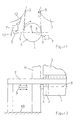
- the dryer section consists of two rows of rollers 3, 4, the upper rollers 3 as a heated drying cylinder and the lower rollers 4 as suction guide rollers are trained.
- the suctioned guide rollers have a perforated one Roll shell, the interior of which is connected to a vacuum source.
- the fibrous web 1 For Drying the fibrous web 1, this is alternately over the heated Drying cylinder and suction guided guide rollers, the fibrous web 1 at least within a drying group of the dryer section from one belt 2 is supported in the form of a dryer fabric and directly with the drying cylinders in Contact comes.
- the fibrous web 1 runs between the upper and lower Roll 3.4 together with the belt 2 at an angle ⁇ of 20 ° to one Vertical 5.
- a sensor 6 for measuring the Temperature and moisture content of the fibrous web 1. These measurements are in influencing the moisture cross profile of the fibrous web 1 by Steam blow boxes, nozzle dampers etc. are taken into account.
- the sensor 6 is on a sensor guide 7 attached traversable, which the detection of Web parameters allowed across the entire fibrous web 1.
- a sensor 6 with its sensor guide 7 is opposite the lower roller 4 arranged, the fibrous web 1 with the tape 2 from the upper 3 to lower 4 roller runs.
- the sensor 6 lies on the axis 8 of the lower one Roller 4 extending horizontal 9.
- the distance between sensor 6 and Fiber web 1 is approximately 10 cm. The gap formed in this way is sufficient large so that contaminants can easily fall into the machine basement where they are collected and discharged.
- a scraper 12 also acts on the upper roller 3, its scraper blade Contaminants removed from the upper roller 3.
- This scraper 12 is like this trained that the impurities scraped off by it through the gap can fall between sensor 6 and fibrous web 1.
- a baffle 13 additionally protect the sensor 6 and the sensor guide 7 against contamination.
- the sensor 6 and if possible also the Sensor guide 7 are arranged in a position in which they are in relation to the axis 8 the lower roller 4 with the horizontal 9 forms an angle ⁇ of at most 60 °. Since, as indicated, the sensor 6 and the sensor guide 7 here under the axis 8 of the lower roller 4, the angle ⁇ is much smaller, namely about 20 °. This small angle ⁇ ensures that falling contaminants are prevented by the Gap between sensor 6 and fibrous web 1, which is approximately 10 cm in size, for example, can fall. Since the fibrous web 1 runs here to the upper roller 3, entrained ones and sloping railway remains rather rare, so that further protective measures can be dispensed with.
- Figure 2 shows a section of the chair 11 of the dryer section, which especially the top 3 and bottom 4 rollers.
- the sensor guide 7 is here so far out of the machine that the sensor 6 out of range the roller 3, 4 can be driven. This only allows the sensor 6 to be closed To drive measurement purposes in the hazardous area.
- the sensor guide 7 with the foundation 10 of the Machine connected, which has a positive effect on the measuring accuracy.
Landscapes
- Paper (AREA)
- Treatment Of Fiber Materials (AREA)
Abstract
Description
Claims (14)
- Meßsystem zur Bestimmung von Eigenschaften einer laufenden Papier-, Karton-, Tissue- oder anderen Faserstoffbahn (1), insbesondere in der Trockenpartie einer Maschine zu deren Herstellung und/oder Veredelung angeordnet, in der die Faserstoffbahn (1) zumindest eine obere (3) und eine untere (4) Walze teilweise umschlingt und zwischen diesen Walzen (3,4) in einem Winkel (α) von 0 bis 45° bezüglich einer Senkrechten (5) verläuft, wobei zumindest ein Sensor (6) zur Erfassung einer Bahneigenschaft an einer Sensorführung (7) quer zur Faserstoffbahn (1) traversierend im Bereich der unteren Walze (4) angeordnet ist, dadurch gekennzeichnet, dass
der Sensor (6) in einer Position angeordnet ist, in der er bezüglich der Achse (8) der unteren Walze (4) mit einer Waagerechten (9) ein Winkel (β) von betragsmäßig höchstens 60° bildet. - Meßsystem nach Anspruch 1, dadurch gekennzeichnet, dass
der Sensor (6) unterhalb der Achse (8) der unteren Walze (4) angeordnet ist und bezüglich der Achse (8) der unteren Walze (4) mit der Waagerechten (9) ein Winkel (β) von betragsmäßig höchstens 30° bildet. - Meßsystem nach Anspruch 1, dadurch gekennzeichnet, dass
der Sensor (6) oberhalb der Achse (8) der unteren Walze (4) angeordnet ist. - Meßsystem nach einem der vorhergehenden Ansprüche, dadurch gekennzeichnet, dass
die Sensorführung (7) in einer Position verläuft, in der sie bezüglich der Achse (8) der unteren Walze (4) mit der Waagerechten (9) ein Winkel von betragsmäßig höchstens 60° bildet. - Meßsystem nach Anspruch 4, dadurch gekennzeichnet, dass
die Sensorführung (7) unterhalb der Achse (8) der unteren Walze (4) verläuft und bezüglich der Achse (8) der unteren Walze (4) mit der Waagerechten (9) ein Winkel von betragsmäßig höchstens 30° bildet. - Meßsystem nach Anspruch 4, dadurch gekennzeichnet, dass
die Sensorführung (7) oberhalb der Achse (8) der unteren Walze (4) verläuft. - Meßsystem nach einem der vorhergehenden Ansprüche, dadurch gekennzeichnet, dass
der Sensor (6) vorzugsweise gemeinsam mit der Sensorführung (7) auf der Bahnablaufseite der unteren Walze (4) angeordnet ist. - Meßsystem nach einem der vorhergehenden Ansprüche, dadurch gekennzeichnet, dass
die Sensorführung (7) so gestaltet ist, dass sie eine Bewegung des Sensors (6) wenigstens an einer Seite der Maschine über die Breite der Faserstoffbahn (1), vorzugsweise über die Breite der Walzen (3,4) hinaus erlaubt. - Meßsystem nach einem der vorhergehenden Ansprüche, dadurch gekennzeichnet, dass
die Sensorführung (7) zumindest an einer Seite der Maschine mit deren Stuhlung (11) und/oder Fundament (10) verbunden ist. - Meßsystem nach einem der vorhergehenden Ansprüche, dadurch gekennzeichnet, dass
der Sensor (6) zur Faserstoffbahn (1), vorzugsweise auch zur unteren Walze (4), einen Abstand zwischen 3 und 50 cm, insbesondere zwischen 8 und 25 cm hat. - Meßsystem nach einem der vorhergehenden Ansprüche, dadurch gekennzeichnet, dass
der Sensor (6) die Temperatur und/oder den Feuchtegehalt der Faserstoffbahn (1) erfasst. - Meßsystem nach einem der vorhergehenden Ansprüche, dadurch gekennzeichnet, dass
die obere Walze (3) als beheizter Trockenzylinder ausgebildet ist. - Meßsystem nach einem der vorhergehenden Ansprüche, dadurch gekennzeichnet, dass
die untere Walze (4) als besaugte Leitwalze ausgebildet ist. - Meßsystem nach einem der vorhergehenden Ansprüche, dadurch gekennzeichnet, dass
das Band (2) als Trockensieb ausgebildet ist.
Applications Claiming Priority (2)
| Application Number | Priority Date | Filing Date | Title |
|---|---|---|---|
| DE10019568 | 2000-04-20 | ||
| DE10019568A DE10019568A1 (de) | 2000-04-20 | 2000-04-20 | Meßsystem |
Publications (3)
| Publication Number | Publication Date |
|---|---|
| EP1148174A2 true EP1148174A2 (de) | 2001-10-24 |
| EP1148174A3 EP1148174A3 (de) | 2002-03-27 |
| EP1148174B1 EP1148174B1 (de) | 2005-03-23 |
Family
ID=7639429
Family Applications (1)
| Application Number | Title | Priority Date | Filing Date |
|---|---|---|---|
| EP01105142A Expired - Lifetime EP1148174B1 (de) | 2000-04-20 | 2001-03-02 | Messsystem |
Country Status (3)
| Country | Link |
|---|---|
| US (1) | US6523401B2 (de) |
| EP (1) | EP1148174B1 (de) |
| DE (2) | DE10019568A1 (de) |
Families Citing this family (6)
| Publication number | Priority date | Publication date | Assignee | Title |
|---|---|---|---|---|
| DE10321865B4 (de) * | 2003-05-14 | 2013-06-27 | Betriebsforschungsinstitut VDEh - Institut für angewandte Forschung GmbH | Messvorrichtung für ein längsbewegtes Band und Messverfahren für Prozessparameter einer Bandförderung |
| DE102007023480A1 (de) | 2007-05-19 | 2008-11-20 | Voith Patent Gmbh | Vorrichtung zur Sauberhaltung eines Schutzgehäuses |
| US9481777B2 (en) | 2012-03-30 | 2016-11-01 | The Procter & Gamble Company | Method of dewatering in a continuous high internal phase emulsion foam forming process |
| US11707906B2 (en) | 2020-08-27 | 2023-07-25 | Buckman Laboratories International, Inc. | Predictive control of Yankee dryer chemistry and creped product quality |
| CN118974672A (zh) | 2022-03-24 | 2024-11-15 | 巴克曼实验室国际公司 | 用于关于在线传感器的追溯和自动验证或校正动作的系统和方法 |
| DE202023001065U1 (de) | 2023-05-13 | 2023-07-07 | Mark Fellinger | Vorrichtung zum Schutz eines Kameraobjektivs vor Verunreinigungen |
Family Cites Families (4)
| Publication number | Priority date | Publication date | Assignee | Title |
|---|---|---|---|---|
| US5400258A (en) * | 1993-09-03 | 1995-03-21 | Measurex Corporation | Automatic cross-directional control zone alignment for sheetmaking systems |
| DE29509461U1 (de) * | 1995-06-09 | 1995-08-24 | Voith Sulzer Papiermaschinen GmbH, 89522 Heidenheim | Trockenpartie |
| FI111469B (fi) * | 1996-12-16 | 2003-07-31 | Metso Paper Inc | Menetelmä ja järjestelmä radan irtoamistapahtuman seuraamiseksi |
| DE19911395A1 (de) * | 1999-03-15 | 2000-09-21 | Voith Sulzer Papiertech Patent | Vorrichtung zum Bestimmen von Eigenschaften einer laufenden Materialbahn und/oder einer Maschine zu deren Herstellung und/oder Veredelung |
-
2000
- 2000-04-20 DE DE10019568A patent/DE10019568A1/de not_active Withdrawn
-
2001
- 2001-03-02 EP EP01105142A patent/EP1148174B1/de not_active Expired - Lifetime
- 2001-03-02 DE DE50105665T patent/DE50105665D1/de not_active Expired - Lifetime
- 2001-03-26 US US09/816,390 patent/US6523401B2/en not_active Expired - Lifetime
Also Published As
| Publication number | Publication date |
|---|---|
| US20010032502A1 (en) | 2001-10-25 |
| US6523401B2 (en) | 2003-02-25 |
| DE10019568A1 (de) | 2001-10-25 |
| EP1148174A3 (de) | 2002-03-27 |
| EP1148174B1 (de) | 2005-03-23 |
| DE50105665D1 (de) | 2005-04-28 |
Similar Documents
| Publication | Publication Date | Title |
|---|---|---|
| DE3807857C2 (de) | ||
| DE3716902A1 (de) | Vorrichtung zum reinigen einer walze an kalandern, glaettwerken u. dgl. | |
| DE4311402A1 (de) | Meßvorrichtung zum Messen des Zustands eines Papiermaschinenfilzes | |
| WO2008141874A2 (de) | Vorrichtung zur sauberhaltung eines schutzgehäuses | |
| DE3344217C2 (de) | ||
| EP1148174B1 (de) | Messsystem | |
| DE4121432A1 (de) | Geraet zum messen des zustands eines filzes und zum instandsetzen des filzes | |
| EP2098628B1 (de) | Verfahren zum Mangeln von Wäschestücken und Muldenmangel | |
| DE19882574C2 (de) | Verfahren und Vorrichtung zur Trocknung einer Stoffbahn | |
| DE102007038133A1 (de) | Vorrichtung zur Herstellung einer Faserstoffbahn, insbesondere Papier-, Karton- oder Tissuebahn | |
| EP0575371B1 (de) | Verfahren zur behebung von planlagestörungen bei der herstellung von bahnen, insbesondere in kartonmaschinen und vorrichtung zu seiner durchführung | |
| DE19805723A1 (de) | Trockenpartie sowie Verfahren zum Betreiben einer solchen Trockenpartie | |
| AT507608B1 (de) | Anordnung zum konditionieren eines pressengewebes in einer faserbahnmaschine | |
| DE19936191C2 (de) | Vorrichtung zur Wärmebehandlung von durchlaufenden Bahnen | |
| EP1234911A2 (de) | Feuchtequerprofil | |
| DD262256A5 (de) | Verfahren und vorrichtung zur stabilisierten fuehrung einer bewegten materialbahn | |
| DE102009027860A1 (de) | Saug- oder Blaswalze | |
| DE202011108575U1 (de) | Prüfeinrichtung und Vorrichtung zur Herstellung und/oder Veredelung einer Materialbahn | |
| DE102009027608A1 (de) | Trockenpartie | |
| DE10025240A1 (de) | Verfahren und Vorrichtung zur Feuchtequerprofil-Korrektur | |
| EP1960594B1 (de) | Bahnüberwachung | |
| DE202024104632U1 (de) | Erfassungskonstruktion in einer Faserbahnmaschine | |
| WO2012034992A1 (de) | Messvorrichtung | |
| DE9419580U1 (de) | Wäschetrockner mit Aktiv-Flusenabscheidung | |
| AT16528U1 (de) | Glättvorrichtung |
Legal Events
| Date | Code | Title | Description |
|---|---|---|---|
| PUAI | Public reference made under article 153(3) epc to a published international application that has entered the european phase |
Free format text: ORIGINAL CODE: 0009012 |
|
| AK | Designated contracting states |
Kind code of ref document: A2 Designated state(s): AT BE CH CY DE DK ES FI FR GB GR IE IT LI LU MC NL PT SE TR Kind code of ref document: A2 Designated state(s): DE FI SE |
|
| AX | Request for extension of the european patent |
Free format text: AL;LT;LV;MK;RO;SI |
|
| PUAL | Search report despatched |
Free format text: ORIGINAL CODE: 0009013 |
|
| AK | Designated contracting states |
Kind code of ref document: A3 Designated state(s): AT BE CH CY DE DK ES FI FR GB GR IE IT LI LU MC NL PT SE TR |
|
| AX | Request for extension of the european patent |
Free format text: AL;LT;LV;MK;RO;SI |
|
| 17P | Request for examination filed |
Effective date: 20020927 |
|
| AKX | Designation fees paid |
Free format text: DE FI SE |
|
| GRAP | Despatch of communication of intention to grant a patent |
Free format text: ORIGINAL CODE: EPIDOSNIGR1 |
|
| GRAS | Grant fee paid |
Free format text: ORIGINAL CODE: EPIDOSNIGR3 |
|
| GRAA | (expected) grant |
Free format text: ORIGINAL CODE: 0009210 |
|
| AK | Designated contracting states |
Kind code of ref document: B1 Designated state(s): DE FI SE |
|
| REG | Reference to a national code |
Ref country code: IE Ref legal event code: FG4D Free format text: GERMAN |
|
| REF | Corresponds to: |
Ref document number: 50105665 Country of ref document: DE Date of ref document: 20050428 Kind code of ref document: P |
|
| REG | Reference to a national code |
Ref country code: SE Ref legal event code: TRGR |
|
| PLBE | No opposition filed within time limit |
Free format text: ORIGINAL CODE: 0009261 |
|
| STAA | Information on the status of an ep patent application or granted ep patent |
Free format text: STATUS: NO OPPOSITION FILED WITHIN TIME LIMIT |
|
| 26N | No opposition filed |
Effective date: 20051227 |
|
| PGFP | Annual fee paid to national office [announced via postgrant information from national office to epo] |
Ref country code: DE Payment date: 20150320 Year of fee payment: 15 Ref country code: FI Payment date: 20150311 Year of fee payment: 15 |
|
| PGFP | Annual fee paid to national office [announced via postgrant information from national office to epo] |
Ref country code: SE Payment date: 20150319 Year of fee payment: 15 |
|
| REG | Reference to a national code |
Ref country code: DE Ref legal event code: R119 Ref document number: 50105665 Country of ref document: DE |
|
| PG25 | Lapsed in a contracting state [announced via postgrant information from national office to epo] |
Ref country code: FI Free format text: LAPSE BECAUSE OF NON-PAYMENT OF DUE FEES Effective date: 20160302 |
|
| REG | Reference to a national code |
Ref country code: SE Ref legal event code: EUG |
|
| PG25 | Lapsed in a contracting state [announced via postgrant information from national office to epo] |
Ref country code: SE Free format text: LAPSE BECAUSE OF NON-PAYMENT OF DUE FEES Effective date: 20160303 |
|
| PG25 | Lapsed in a contracting state [announced via postgrant information from national office to epo] |
Ref country code: DE Free format text: LAPSE BECAUSE OF NON-PAYMENT OF DUE FEES Effective date: 20161001 |