EP1146152A1 - Stützscheibe mit Kautschukbelag für eine Stützscheibenlagerung für Spinnrotoren - Google Patents
Stützscheibe mit Kautschukbelag für eine Stützscheibenlagerung für Spinnrotoren Download PDFInfo
- Publication number
- EP1146152A1 EP1146152A1 EP01108550A EP01108550A EP1146152A1 EP 1146152 A1 EP1146152 A1 EP 1146152A1 EP 01108550 A EP01108550 A EP 01108550A EP 01108550 A EP01108550 A EP 01108550A EP 1146152 A1 EP1146152 A1 EP 1146152A1
- Authority
- EP
- European Patent Office
- Prior art keywords
- support disc
- covering
- rubber
- support
- disc according
- Prior art date
- Legal status (The legal status is an assumption and is not a legal conclusion. Google has not performed a legal analysis and makes no representation as to the accuracy of the status listed.)
- Granted
Links
Images


Classifications
-
- D—TEXTILES; PAPER
- D01—NATURAL OR MAN-MADE THREADS OR FIBRES; SPINNING
- D01H—SPINNING OR TWISTING
- D01H4/00—Open-end spinning machines or arrangements for imparting twist to independently moving fibres separated from slivers; Piecing arrangements therefor; Covering endless core threads with fibres by open-end spinning techniques
- D01H4/04—Open-end spinning machines or arrangements for imparting twist to independently moving fibres separated from slivers; Piecing arrangements therefor; Covering endless core threads with fibres by open-end spinning techniques imparting twist by contact of fibres with a running surface
- D01H4/08—Rotor spinning, i.e. the running surface being provided by a rotor
- D01H4/12—Rotor bearings; Arrangements for driving or stopping
Definitions
- the present application relates to a support disc for a support disc bearing for open-end spinning rotors according to the preamble of the claim 1.
- Generic support disks are for example by a storage for Spinning rotors known from DE 33 24 129 A1.
- the support washers exist from a base body, for example made of plastic or metal and which has a plastic ring on its outer circumference, which forms the tread for the mounted rotor shaft.
- the plastic ring is applied to the base body by spraying onto it. That in material used for this in the prior art for the
- the circumference of the rotor shaft running plastic ring is a polyurethane elastomer.
- This elastic plastic ring which forms the tread for the rotor shaft, has the property that it has damping properties, so that the troubled run of the spinning rotor, for example due to imbalance or through Impacts of the driving tangential belt takes place, can be damped.
- the known support disc bearings and the support discs with one Trims made of polyurethane are speeds of the rotor shaft up to possible at 110,000 revolutions per minute and more.
- the support disc coverings are made of polyurethane but also the disadvantage that they wear out. Through the constant Deformation on the surface of the tread, for example warmed so much by the flexing that the covering is destroyed takes place. To suppress this behavior of the support disks is out known in the prior art, a cooling groove in the covering of the support disc bring in. This is shown, for example, in US Pat. No. 5,178,473.
- the known support disks have the further disadvantage that the polyurethane tread detaches from the base, causing destruction the support disc takes place.
- the plastic covering is applied to a base body, which is designed such that in a radial Viewed in the direction of the support disc, a positive connection is present between the base body and the plastic covering.
- Such Support disc is known for example from DE 42 27 489 A1. From the DE 19824286 A1 discloses a support disk which is located next to a cooling groove still has a cleaning groove and provides for other measures to contamination of the rotor spinning device during operation To prevent the rotor shaft, which gives rise to additional maintenance work gives.
- the object of the present application is to overcome the disadvantages of the prior art Eliminate technology and propose a support disc that is suitable To store open-end spinning rotors even at the highest speeds without the Disadvantage of having an insufficient lifespan.
- the object of the present invention is achieved by a support disk solved the claim 1.
- the inventive design of the support disc is advantageous achieved that between the base body and the tread of the support disc secure connection is created, even at the highest speeds and stresses, such as those caused by flexing work Resists forces. There is no detachment of the covering from the base body instead of.
- the support disk designed according to the invention has very good rolling properties for the mounted rotor shaft. So be an uneven running behavior of the rotor due to the good damping properties the support disc is considerably reduced and vibrations dampened.
- the damping work occurring in the covering of the support disc can be advantageously taken up by the covering without causing any impairments the quality of the tread of the support disc comes.
- the covering of the support disc has a cooling groove for an even better removal of those arising during operation Warmth from the surface. This further increases wear resistance the support disc.
- the coating By forming the coating with a cleaning groove to prevent deposits on the rotor shaft, malfunctions in operation are reduced. These are also advantageously prevented by the fact that the covering of the support disk has a low electrical resistance of advantageously less than 1.0 x 10 9 ohms.
- the rubber material is advantageously mixed with an additive to increase its electrical conductivity.
- the covering of the support disk is made made of nitrile rubber (NBR).
- NBR nitrile rubber
- the rubber can contain additives so that it has no aging time required, such as the polyurethane used in the prior art. With these additives, NBR or H-NBR behaves like an already aged one Material and therefore has constant properties from the start.
- a rubber with a tensile strength of at least 28 N / mm 2 is advantageously used for the advantageous development of the invention.
- a rubber with a Shore A hardness of 85 to 105 is advantageously used. This achieves favorable damping values for the bearing.
- the use of a rubber for the support disc with an elasticity of at least 29% ensures high wear resistance with good damping.
- the support disc has one or more on the circumference of the covering Grooves, so can the support disc covering in a particularly advantageous manner Withstand even the highest loads.
- the groove can do several tasks fulfill. For example, it can be used to cool the surface or to Cleaning the shaft of the open spinning rotor can be used. By the Use of the grooves is also the rolling resistance of the Shaft influenced on the support discs.
- the covering is less than 4 mm thick or less than 1.9 times the height of the deepest groove, so there is a particularly good ratio of the covering in terms of its strength and the cooling and cleaning effects surrendered to the groove.
- one or more cleaning grooves are arranged on the covering of the support disc.
- the base body surface treated especially if it is at the body is an aluminum part, anodized, so several achieved additional benefits.
- the surface treatment causes damage of the material of the base body, for example by oxidation prevented.
- the surface treatment is colored Markings of the base body possible, so that the use of different Support discs can be color-coded in a simple manner and thus confusion can be avoided.
- the material of the covering of the support disks according to the invention even possible that, for example, an anodized layer even after application the covering of the support disc can be applied. Through the for example anodized layer, i. H. the anodizing of the support disc too with its covering, the covering is not attacked and its effect is not reduced. The anodizing can be done after finishing the support disc respectively.
- Support discs according to the invention with an outer diameter between 50 and 80 mm have been used for the storage of spinning rotors proven to be particularly good.
- the contact surface between the lining and the rotor shaft advantageously has a width between 4 and 12 mm. This is sufficient to one hand a largely slip-free rolling process of the rotor shaft on the To effect support disks and on the other hand the rolling resistance as possible to keep low.
- a value of approximately 2 mm has been found to be special as the minimum width of a covering proven advantageous. With this value it is even possible a direct attachment of the covering to the circumference of the base body without to make lateral contact between the base body and the covering. It is sufficient here, in particular for an aluminum body Liability of the covering according to the invention given. Also are the 2 mm is sufficient to prevent the covering from buckling to the side.
- FIG. 1 shows a schematic diagram of a bearing 1 for an open-end spinning rotor 2, as used as standard on open-end spinning machines is coming.
- the storage 1 consists essentially of a bearing block 11, which supports the support disc bearings 12.
- the support disc bearings 12 each store a shaft 13, which in turn at each of its ends via a press connection is connected to a support disc 14.
- the support disks 14 each form two Support disc pairs so that two wedge gaps 141 are formed.
- the support washers 14 carry the rotor shaft 21 of the open-end spinning rotor 2. Will the open-end spinning rotor 2, for example via a tangential belt (not shown) driven, it rolls in the wedge gaps 141 on the support disks 14 from. This causes them to rotate.
- the support disks 14 are provided with a cleaning groove 3, which during rotation of the support discs 14 moves with its edges 31 along the line of contact of the rotor shaft.
- the cleaning groove 3 is introduced into the covering 143 in the form of an endless groove. Since the discharge of the rotor shaft 21 on the support disks 14 is not is slip-free, it is ensured that the edge 31 every point of the rotor shaft reached and cleans it of deposits.
- the shafts 13, which receive and support the support disks, are mutually not parallel, but skewed, so that on the rotor shaft 21 an axial thrust is exerted by the support disks.
- This is supported in a known manner from an axial bearing 101.
- This can, for example be designed as a thrust bearing, or as in the exemplary embodiment of FIG. 1 indicated, in the form of an aerostatic thrust bearing.
- This proof is required around the slip between the tangential belt and the rotor shaft 21 keep small, so that the rotor shaft 21 and with it that of this mounted open-end spinning rotor 2 driven largely lossless can be.
- This contact pressure must be from the pad 143 of each support disc 14 are included. In that the support discs rotate and the rotor shaft 21 rolls on it, the pad 143 is a changing Exerted pressure force, which claims the pad 143. The strain due to the changing pressure force, the covering 143 heats up, and thus to a thermal load.
- the support disk 14 shown in section in FIG. 2 has a cleaning groove 3 in the pad 143. This forms the tread on its outer circumference 144 on which the rotor shaft 21 rolls.
- the support disk 14 consists of a base body 5, for example made of aluminum, as an injection molded part can be formed, or also consists of plastic.
- the support disc 14 has a bore 51 in its center through which it bears on the shaft 13 a support disc bearing 12 are attached by means of an interference fit can (see Figure 1).
- the outer circumference of the base body 5 in particular, cannot shown type, for example V-shaped or hammer-shaped, thus ensuring better adhesion between base body 5 and pad 143 can be.
- the base body 5 designed so that in the area of a groove in the covering 143, here the cleaning groove 3, there is a sufficient thickness of the covering 143.
- This liability is in a trained according to the invention Support disc much higher than with support discs of the state of Technology in which the pad 143 is made of polyurethane.
- the invention Rubber cover has a much higher inherent Adhesive force on the base body as coverings of the prior art.
- the rubber support disc covering according to the invention tends less cavities, which further improves its adhesive force.
- a covering 143 of the support disk 14 made of rubber, in particular of nitrile rubber, allows covering 143 as a thin layer on the outer circumference to apply the base body 5.
- the support disc 14 shown in Figure 3, the representation of which is also in Cut has a base body 5, which has a flat, cylindrical Has area on the circumference on which the rubber covering 143 is applied according to the invention. Due to the special physical Properties of the rubber, especially its favorable adhesive strength, the if necessary, through adhesion promoters and / or roughening the contact surface can still be significantly improved, it is possible without one on the outer circumference profiled base body 5, a secure connection between cover 143 and base body 5.
- the covering 143 used in FIG. 3 has a center over the circumference extending groove 30, the task of a cooling groove for cooling the Has 143. Such grooves used for cooling are in the prior art Technology common.
- the support disk covering material a further embodiment of the support disk covering, in particular the tread 144, since the covering 143 according to the invention is more resistant, i.e. is more wear resistant. For example, this can result in narrower support disks are used, which advantageously makes the bearing smaller and has a lower mass. Also an advantageous reduction in diameter the support washers is due to the material of the invention now possible for the tread.
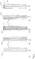
- FIG. 4 shows various exemplary embodiments of one in each case according to the invention Support disc shown.
- the embodiment a shows a groove 30 in a covering 143, which almost touches the base body 5 (dashed line).
- a particularly stable design is created on its inner circumference, because there is a two-piece covering on the outside at its fastening point mutually supportive.
- FIG. 4b shows a support disk 14 which has two grooves 30 in its Has circumference. As a result, there are three support surfaces for the rotor shaft created by the covering 143.
- FIG. 4c three grooves 30 are arranged in the support disk covering 143. As shown in the section in FIG. 4c, the outer two are sufficient of the grooves 30 less deep into the covering thickness than the middle, third groove it does.
- the middle groove 30 is as close as shown in Figure 4a cut the base body 5 into the covering 143.
- Figure 4d shows cleaning grooves 3 which are inclined in the axial direction in the Pad 143 are arranged. This creates an axial force on the pollution of the rotor shaft, whereby this is gradually released and the rotor shaft is kept almost free of dirt in this area.
- a support disc 14 which consists of two linings 143 exists. Each of these pads 143 is without contact with the other Cover 143 attached to the base body 5 of the support plate 14. Through the The peculiarity of the material of the covering 143 is particularly good adhesion in this version, in which no or only a small side Contact with the base body 5 of the support disk 14 is sufficient.
- a support disk bearing designed according to the invention is general less sensitive to manufacturing and assembly tolerances and enables thereby cheaper production. For example possible without subsequent machining of the support disc cover spray on. Only the peripheral surface is for fine machining to edit.
- the rubber naturally has a lower electrical resistance in comparison to the supporting disc covering of supporting discs of the stand of the technique.
Abstract
Description
- Figur 1
- Eine Prinzipdarstellung einer Lagerung für einen OffenendSpinnrotor;
- Figur 2
- einen Schnitt durch eine Stützscheibe der Lagerung von Figur 1;
- Figur 3
- einen Schnitt durch eine Stützscheibe mit ebener Umfangsfläche des Grundkörpers;
- Figur 4
- verschiedene Ausführungsbeispiele einer erfindungsgemäßen Stützscheibe.
Claims (18)
- Stützscheibe für eine Stützscheibenlagerung eines Offenend-Spinnrotors (2), die einen Grundkörper (5) besitzt mit einer Verbindung für eine Welle (13) zur Lagerung der Stützscheibe (14) und einem Außenumfang zur Aufnahme eines Belages (143) aus Kunststoff zur Lagerung eines Offenend-Spinnrotors, (2) dadurch gekennzeichnet, daß der Belag (143) aus Kautschuk ist.
- Stützscheibe nach Anspruch 1, dadurch gekennzeichnet, daß der Belag (143) im wesentlichen aus Nitrilkautschuk (NBR) besteht.
- Stützscheibe nach Anspruch 1 oder 2, dadurch gekennzeichnet, daß der Belag (143) im wesentlichen aus dem Kautschuk H-NBR besteht.
- Stützscheibe nach einem oder mehreren der Ansprüche 1 bis 3, dadurch gekennzeichnet, daß der Belag (143) aus Kautschuk mit einer Reißfestigkeit von wenigstens 28 N/mm2 besteht.
- Stützscheibe nach einem oder mehreren der Ansprüche 1 bis 4, dadurch gekennzeichnet, daß der Belag (143) aus einem Kautschuk mit einer Härte zwischen Shore A 85 und 105 besteht.
- Stützscheibe nach einem oder mehreren der Ansprüche 1 bis 5, dadurch gekennzeichnet, daß der Kautschuk eine Härte zwischen 45 und 70 Shore D besitzt.
- Stützscheibe nach einem oder mehreren der Ansprüche 1 bis 6, dadurch gekennzeichnet, daß der Kautschuk eine Elastizität von wenigstens 29 % besitzt.
- Stützscheibe nach einem oder mehreren der Ansprüche 1 bis 7, dadurch gekennzeichnet, daß die Stützscheibe (14) auf dem Umfang des Belages (143) eine oder mehrere Nuten (3, 30) besitzt.
- Stützscheibe nach einem oder mehreren der Ansprüche 1 bis 8, dadurch gekennzeichnet, daß die Nut(en) (3, 30) bis zum Grundkörper (5) reichen.
- Stützscheibe nach einem oder mehreren der Ansprüche 1 bis 9, dadurch gekennzeichnet, daß die Stützscheibe wenigstens eine Nut (30) zur Kühlung des Belags (143) auf dem Umfang des Belages (143) besitzt.
- Stützscheibe nach einem oder mehreren der Ansprüche 1 bis 10, dadurch gekennzeichnet, daß der Belag (143) eine Dicke von weniger als 4 mm besitzt oder weniger als dem 1,9-fachen der tiefsten Nut (3, 30).
- Stützscheibe nach einem oder mehreren der Ansprüche 1 bis 11, dadurch gekennzeichnet, daß der Belag (143) der Stützscheibe (14) auf dem Umfang mindestens eine, vorzugsweise zwei Reinigungsnuten (3) besitzt.
- Stützscheibe nach einem oder mehreren der Ansprüche 1 bis 12, dadurch gekennzeichnet, daß der elektrische Widerstand des Belags (143) einen Wert von weniger als 1,0 x 10⁹ Ohm hat.
- Stützscheibe nach einem oder mehreren der Ansprüche 1 bis 13, dadurch gekennzeichnet, daß der Belag (143) einen Zusatz enthält zur Verminderung des elektrischen Widerstandes auf unter 1,0 x 10⁹ Ohm.
- Stützscheibe nach einem oder mehreren der Ansprüche 1 bis 14, dadurch gekennzeichnet, daß der Grundkörper (5), insbesondere nach dem Aufbringen des Belages (143) oberflächenbehandelt, insbesondere eloxiert ist.
- Stützscheibe nach einem oder mehreren der Ansprüche 1 bis 15, dadurch gekennzeichnet, daß die Stützscheibe (14) einen Außendurchmesser zwischen 50 und 80 mm aufweist.
- Stützscheibe nach einem oder mehreren der Ansprüche 1 bis 16, dadurch gekennzeichnet, daß die Kontaktfläche zwischen Belag (143) und Rotorschaft (21) eine Breite zwischen 4 und 12 mm aufweist.
- Stützscheibe nach einem oder mehreren der Ansprüche 1 bis 17, dadurch gekennzeichnet, daß die Mindestbreite eines Belages (143) 2 mm beträgt.
Applications Claiming Priority (2)
| Application Number | Priority Date | Filing Date | Title |
|---|---|---|---|
| DE10018440A DE10018440A1 (de) | 2000-04-13 | 2000-04-13 | Stützscheibe für eine Stützscheibenlagerung für Spinnrotoren |
| DE10018440 | 2000-04-13 |
Publications (2)
| Publication Number | Publication Date |
|---|---|
| EP1146152A1 true EP1146152A1 (de) | 2001-10-17 |
| EP1146152B1 EP1146152B1 (de) | 2004-12-29 |
Family
ID=7638681
Family Applications (1)
| Application Number | Title | Priority Date | Filing Date |
|---|---|---|---|
| EP01108550A Expired - Lifetime EP1146152B1 (de) | 2000-04-13 | 2001-04-05 | Stützscheibe mit Kautschukbelag für eine Stützscheibenlagerung für Spinnrotoren |
Country Status (4)
| Country | Link |
|---|---|
| US (1) | US6688775B2 (de) |
| EP (1) | EP1146152B1 (de) |
| AT (1) | ATE286161T1 (de) |
| DE (2) | DE10018440A1 (de) |
Cited By (5)
| Publication number | Priority date | Publication date | Assignee | Title |
|---|---|---|---|---|
| EP1327707A1 (de) * | 2002-01-10 | 2003-07-16 | Rieter Ingolstadt Spinnereimaschinenbau AG | Grundkörper für die Stützscheibe einer OE-Rotorlagerung |
| DE10230171A1 (de) * | 2002-02-08 | 2003-08-21 | Rieter Ingolstadt Spinnerei | Stützscheibe für die Lagerung eins Offenend-Spinnrotors |
| CN103398094A (zh) * | 2013-07-26 | 2013-11-20 | 苏州天华有色金属制品有限公司 | 一种具有双向圆形滑槽的圆盘 |
| CN103518009A (zh) * | 2012-05-09 | 2014-01-15 | 后藤义一 | 自由端精纺机的转子轴支撑盘 |
| WO2017194433A1 (de) * | 2016-05-13 | 2017-11-16 | Rieter Ingolstadt Gmbh | Spinnrotor für eine offenend-spinnvorrichtung mit einem reibwerterhöhenden belag aus einem elastomeren material und offenend-spinnvorrichtung |
Families Citing this family (4)
| Publication number | Priority date | Publication date | Assignee | Title |
|---|---|---|---|---|
| US6332893B1 (en) * | 1997-12-17 | 2001-12-25 | Myocor, Inc. | Valve to myocardium tension members device and method |
| DE10237007A1 (de) * | 2001-11-29 | 2003-06-12 | Rieter Ingolstadt Spinnerei | Stützscheibe und Lagerung für einen Spinnrotor |
| DE102012014660A1 (de) * | 2012-07-24 | 2014-01-30 | Saurer Germany Gmbh & Co. Kg | Stützscheibenlagerung für eine Offenend-Spinneinrichtung |
| DE102015104491A1 (de) | 2015-03-25 | 2016-09-29 | Rieter Ingolstadt Gmbh | Spinnrotor mit einem Laufbelag, Stützscheibe zur Lagerung eines Spinnrotors sowie Offenendspinnvorrichtung mit einem Spinnrotor und einer Lagervorrichtung mit Stützscheiben |
Citations (2)
| Publication number | Priority date | Publication date | Assignee | Title |
|---|---|---|---|---|
| DE4227489A1 (de) * | 1992-08-20 | 1994-03-10 | Schurr Stahlecker & Grill | Stützscheibe für eine Stützscheibenlagerung für OE-Spinnrotoren |
| DE19824286A1 (de) * | 1998-05-29 | 1999-12-02 | Rieter Ingolstadt Spinnerei | Lagerung für einen Offenend-Spinnrotor mittels Stützscheiben |
Family Cites Families (11)
| Publication number | Priority date | Publication date | Assignee | Title |
|---|---|---|---|---|
| DE3324129A1 (de) | 1983-07-05 | 1985-01-17 | Fritz 7347 Bad Überkingen Stahlecker | Lagerung und antrieb fuer einen spinnrotor einer offenend-spinnvorrichtung |
| DE3342768A1 (de) * | 1983-11-25 | 1985-06-05 | Schubert & Salzer Maschinenfabrik Ag, 8070 Ingolstadt | Stuetzscheibenlager |
| US5178473A (en) | 1983-11-25 | 1993-01-12 | Schubert & Salzer Maschinenfabrik Aktiengesellschaft | Supporting-disk bearing |
| DE3615777A1 (de) * | 1986-05-10 | 1987-11-12 | Stahlecker Fritz | Stuetzscheibe fuer eine stuetzscheibenlagerung eines oe-spinnrotors |
| US4892422A (en) * | 1988-08-01 | 1990-01-09 | American Suessen Corporation | Support assembly for the rotor of an open end yarn spinning apparatus |
| DE3826851C2 (de) * | 1988-08-06 | 1996-01-11 | Stahlecker Fritz | Stützscheibe für eine Stützscheibenlagerung von OE-Spinnrotoren |
| US4893946A (en) * | 1989-05-15 | 1990-01-16 | Amkor Industries, Inc. | Roller for spinning frame |
| DE4121387C2 (de) * | 1991-06-28 | 2000-12-14 | Schlafhorst & Co W | Stützscheibenlagerung einer Rotorspinneinrichtung |
| DE19712916A1 (de) * | 1997-03-27 | 1998-10-01 | Novibra Gmbh | Stützscheibe für eine Stützscheibenlagerung von OE-Spinnrotoren |
| DE19845237A1 (de) * | 1998-10-01 | 2000-04-06 | Schlafhorst & Co W | Stützscheibe einer Rotorspinneinrichtung |
| DE19908922B4 (de) | 1999-03-02 | 2007-04-19 | Carl Freudenberg Kg | Stützscheibe für die Lagerung eines Rotors |
-
2000
- 2000-04-13 DE DE10018440A patent/DE10018440A1/de not_active Withdrawn
-
2001
- 2001-04-05 DE DE50104923T patent/DE50104923D1/de not_active Expired - Lifetime
- 2001-04-05 AT AT01108550T patent/ATE286161T1/de not_active IP Right Cessation
- 2001-04-05 EP EP01108550A patent/EP1146152B1/de not_active Expired - Lifetime
- 2001-04-11 US US09/833,086 patent/US6688775B2/en not_active Expired - Lifetime
Patent Citations (2)
| Publication number | Priority date | Publication date | Assignee | Title |
|---|---|---|---|---|
| DE4227489A1 (de) * | 1992-08-20 | 1994-03-10 | Schurr Stahlecker & Grill | Stützscheibe für eine Stützscheibenlagerung für OE-Spinnrotoren |
| DE19824286A1 (de) * | 1998-05-29 | 1999-12-02 | Rieter Ingolstadt Spinnerei | Lagerung für einen Offenend-Spinnrotor mittels Stützscheiben |
Non-Patent Citations (1)
| Title |
|---|
| J.WEIR & R.C. BERKEY: "Carboxylierter Nitrilkautschuk-Eigenschaften und Anwendung", GUMMI.ASBEST.KUNSTSTOFFE, vol. 36, no. 6, 1983, Stuttgart,Deutschland, pages 268 - 274, XP002173274 * |
Cited By (6)
| Publication number | Priority date | Publication date | Assignee | Title |
|---|---|---|---|---|
| EP1327707A1 (de) * | 2002-01-10 | 2003-07-16 | Rieter Ingolstadt Spinnereimaschinenbau AG | Grundkörper für die Stützscheibe einer OE-Rotorlagerung |
| DE10230171A1 (de) * | 2002-02-08 | 2003-08-21 | Rieter Ingolstadt Spinnerei | Stützscheibe für die Lagerung eins Offenend-Spinnrotors |
| CN103518009A (zh) * | 2012-05-09 | 2014-01-15 | 后藤义一 | 自由端精纺机的转子轴支撑盘 |
| CN103518009B (zh) * | 2012-05-09 | 2016-02-03 | 后藤义一 | 自由端精纺机的转子轴支撑盘 |
| CN103398094A (zh) * | 2013-07-26 | 2013-11-20 | 苏州天华有色金属制品有限公司 | 一种具有双向圆形滑槽的圆盘 |
| WO2017194433A1 (de) * | 2016-05-13 | 2017-11-16 | Rieter Ingolstadt Gmbh | Spinnrotor für eine offenend-spinnvorrichtung mit einem reibwerterhöhenden belag aus einem elastomeren material und offenend-spinnvorrichtung |
Also Published As
| Publication number | Publication date |
|---|---|
| US6688775B2 (en) | 2004-02-10 |
| DE10018440A1 (de) | 2001-10-18 |
| ATE286161T1 (de) | 2005-01-15 |
| DE50104923D1 (de) | 2005-02-03 |
| US20020025094A1 (en) | 2002-02-28 |
| EP1146152B1 (de) | 2004-12-29 |
Similar Documents
| Publication | Publication Date | Title |
|---|---|---|
| EP0144503B1 (de) | Verbindungselement für zwei Maschinen- oder Bauteile, wie Pass-Dehn-Schraube | |
| WO2006119738A1 (de) | Vierreihiges kegelrollenlager | |
| EP1146152B1 (de) | Stützscheibe mit Kautschukbelag für eine Stützscheibenlagerung für Spinnrotoren | |
| EP2094983B1 (de) | Radialwälzlager, insbesondere zur lagerung von wellen in windkraftgetrieben | |
| EP0620298B1 (de) | Offenend-Spinnrotor | |
| EP0541898B1 (de) | Stützscheibe | |
| EP0540818A1 (de) | Stützscheibe | |
| EP0960963A2 (de) | Lagerung für einen Offenend-Spinnrotor mittels Stützscheiben | |
| DE2528485A1 (de) | Aufloesewalze | |
| EP1068382B1 (de) | Ring für ringspinn- und ringzwirnmaschinen | |
| EP0794273B1 (de) | Offenend-Spinnvorrichtung | |
| DE2902820A1 (de) | Lagerung fuer einen offenend-spinnrotor | |
| EP1096045B1 (de) | Lagerung für einen Offenend-Spinnrotor | |
| WO2016150755A1 (de) | Spinnrotor mit einem laufbelag, stützscheibe zur lagerung eines spinnrotors sowie offenendspinnvorrichtung mit einem spinnrotor und einer lagervorrichtung mit stützscheiben | |
| EP0985838B1 (de) | Stützlager und Verfahren zu seiner Herstellung | |
| DE69531073T2 (de) | Verriegelungsmutter | |
| DE102017130339B4 (de) | Rampenscheibe zur Führung des Schmiermittelstromes in einer Axiallageranordnung | |
| DE1685976A1 (de) | Lagerung fuer Spindeln von Spinn- und Zwirnmaschinen | |
| DE102016108860A1 (de) | Stützscheibe für eine Lagerung für einen Schaft eines Offenend-Spinnrotors und Lagerung für einen Schaft eines Offenend-Spinnrotors | |
| DE10237007A1 (de) | Stützscheibe und Lagerung für einen Spinnrotor | |
| EP3455398A1 (de) | Spinnrotor für eine offenend-spinnvorrichtung mit einem reibwerterhöhenden belag aus einem elastomeren material und offenend-spinnvorrichtung | |
| DE10230171A1 (de) | Stützscheibe für die Lagerung eins Offenend-Spinnrotors | |
| DE102011083096A1 (de) | Stoßfestes Kugellager | |
| DE1575519B2 (de) | ||
| DE10039121A1 (de) | Stützscheibe für die Lagerung eines Rotors |
Legal Events
| Date | Code | Title | Description |
|---|---|---|---|
| PUAI | Public reference made under article 153(3) epc to a published international application that has entered the european phase |
Free format text: ORIGINAL CODE: 0009012 |
|
| AK | Designated contracting states |
Kind code of ref document: A1 Designated state(s): AT BE CH CY DE DK ES FI FR GB GR IE IT LI LU MC NL PT SE TR |
|
| AX | Request for extension of the european patent |
Free format text: AL;LT;LV;MK;RO;SI |
|
| 17P | Request for examination filed |
Effective date: 20011124 |
|
| AKX | Designation fees paid |
Free format text: AT BE CH CY DE DK ES FI FR GB GR IE IT LI LU MC NL PT SE TR |
|
| 17Q | First examination report despatched |
Effective date: 20020830 |
|
| GRAP | Despatch of communication of intention to grant a patent |
Free format text: ORIGINAL CODE: EPIDOSNIGR1 |
|
| GRAS | Grant fee paid |
Free format text: ORIGINAL CODE: EPIDOSNIGR3 |
|
| GRAA | (expected) grant |
Free format text: ORIGINAL CODE: 0009210 |
|
| AK | Designated contracting states |
Kind code of ref document: B1 Designated state(s): AT BE CH CY DE DK ES FI FR GB GR IE IT LI LU MC NL PT SE TR |
|
| PG25 | Lapsed in a contracting state [announced via postgrant information from national office to epo] |
Ref country code: GB Free format text: LAPSE BECAUSE OF FAILURE TO SUBMIT A TRANSLATION OF THE DESCRIPTION OR TO PAY THE FEE WITHIN THE PRESCRIBED TIME-LIMIT Effective date: 20041229 Ref country code: FR Free format text: LAPSE BECAUSE OF FAILURE TO SUBMIT A TRANSLATION OF THE DESCRIPTION OR TO PAY THE FEE WITHIN THE PRESCRIBED TIME-LIMIT Effective date: 20041229 Ref country code: IE Free format text: LAPSE BECAUSE OF FAILURE TO SUBMIT A TRANSLATION OF THE DESCRIPTION OR TO PAY THE FEE WITHIN THE PRESCRIBED TIME-LIMIT Effective date: 20041229 Ref country code: NL Free format text: LAPSE BECAUSE OF FAILURE TO SUBMIT A TRANSLATION OF THE DESCRIPTION OR TO PAY THE FEE WITHIN THE PRESCRIBED TIME-LIMIT Effective date: 20041229 Ref country code: ES Free format text: LAPSE BECAUSE OF FAILURE TO SUBMIT A TRANSLATION OF THE DESCRIPTION OR TO PAY THE FEE WITHIN THE PRESCRIBED TIME-LIMIT Effective date: 20041229 Ref country code: FI Free format text: LAPSE BECAUSE OF FAILURE TO SUBMIT A TRANSLATION OF THE DESCRIPTION OR TO PAY THE FEE WITHIN THE PRESCRIBED TIME-LIMIT Effective date: 20041229 |
|
| REG | Reference to a national code |
Ref country code: GB Ref legal event code: FG4D Free format text: NOT ENGLISH |
|
| REG | Reference to a national code |
Ref country code: CH Ref legal event code: EP |
|
| REG | Reference to a national code |
Ref country code: IE Ref legal event code: FG4D Free format text: GERMAN |
|
| REF | Corresponds to: |
Ref document number: 50104923 Country of ref document: DE Date of ref document: 20050203 Kind code of ref document: P |
|
| PG25 | Lapsed in a contracting state [announced via postgrant information from national office to epo] |
Ref country code: DK Free format text: LAPSE BECAUSE OF FAILURE TO SUBMIT A TRANSLATION OF THE DESCRIPTION OR TO PAY THE FEE WITHIN THE PRESCRIBED TIME-LIMIT Effective date: 20050329 Ref country code: GR Free format text: LAPSE BECAUSE OF FAILURE TO SUBMIT A TRANSLATION OF THE DESCRIPTION OR TO PAY THE FEE WITHIN THE PRESCRIBED TIME-LIMIT Effective date: 20050329 Ref country code: SE Free format text: LAPSE BECAUSE OF FAILURE TO SUBMIT A TRANSLATION OF THE DESCRIPTION OR TO PAY THE FEE WITHIN THE PRESCRIBED TIME-LIMIT Effective date: 20050329 |
|
| PG25 | Lapsed in a contracting state [announced via postgrant information from national office to epo] |
Ref country code: CY Free format text: LAPSE BECAUSE OF FAILURE TO SUBMIT A TRANSLATION OF THE DESCRIPTION OR TO PAY THE FEE WITHIN THE PRESCRIBED TIME-LIMIT Effective date: 20050405 Ref country code: LU Free format text: LAPSE BECAUSE OF NON-PAYMENT OF DUE FEES Effective date: 20050405 |
|
| PG25 | Lapsed in a contracting state [announced via postgrant information from national office to epo] |
Ref country code: BE Free format text: LAPSE BECAUSE OF NON-PAYMENT OF DUE FEES Effective date: 20050430 Ref country code: MC Free format text: LAPSE BECAUSE OF NON-PAYMENT OF DUE FEES Effective date: 20050430 |
|
| NLV1 | Nl: lapsed or annulled due to failure to fulfill the requirements of art. 29p and 29m of the patents act | ||
| GBV | Gb: ep patent (uk) treated as always having been void in accordance with gb section 77(7)/1977 [no translation filed] |
Effective date: 20041229 |
|
| REG | Reference to a national code |
Ref country code: IE Ref legal event code: FD4D |
|
| BERE | Be: lapsed |
Owner name: RIETER INGOLSTADT SPINNEREIMASCHINENBAU A.G. Effective date: 20050430 |
|
| PLBE | No opposition filed within time limit |
Free format text: ORIGINAL CODE: 0009261 |
|
| STAA | Information on the status of an ep patent application or granted ep patent |
Free format text: STATUS: NO OPPOSITION FILED WITHIN TIME LIMIT |
|
| 26N | No opposition filed |
Effective date: 20050930 |
|
| EN | Fr: translation not filed | ||
| BERE | Be: lapsed |
Owner name: *RIETER INGOLSTADT SPINNEREIMASCHINENBAU A.G. Effective date: 20050430 |
|
| PG25 | Lapsed in a contracting state [announced via postgrant information from national office to epo] |
Ref country code: PT Free format text: LAPSE BECAUSE OF NON-PAYMENT OF DUE FEES Effective date: 20050529 |
|
| PGFP | Annual fee paid to national office [announced via postgrant information from national office to epo] |
Ref country code: CH Payment date: 20080428 Year of fee payment: 8 |
|
| PGFP | Annual fee paid to national office [announced via postgrant information from national office to epo] |
Ref country code: AT Payment date: 20090423 Year of fee payment: 9 |
|
| REG | Reference to a national code |
Ref country code: CH Ref legal event code: PL |
|
| PG25 | Lapsed in a contracting state [announced via postgrant information from national office to epo] |
Ref country code: LI Free format text: LAPSE BECAUSE OF NON-PAYMENT OF DUE FEES Effective date: 20090430 Ref country code: CH Free format text: LAPSE BECAUSE OF NON-PAYMENT OF DUE FEES Effective date: 20090430 |
|
| PG25 | Lapsed in a contracting state [announced via postgrant information from national office to epo] |
Ref country code: AT Free format text: LAPSE BECAUSE OF NON-PAYMENT OF DUE FEES Effective date: 20100405 |
|
| PGFP | Annual fee paid to national office [announced via postgrant information from national office to epo] |
Ref country code: DE Payment date: 20170503 Year of fee payment: 17 |
|
| PGFP | Annual fee paid to national office [announced via postgrant information from national office to epo] |
Ref country code: IT Payment date: 20170428 Year of fee payment: 17 |
|
| PGFP | Annual fee paid to national office [announced via postgrant information from national office to epo] |
Ref country code: TR Payment date: 20170404 Year of fee payment: 17 |
|
| REG | Reference to a national code |
Ref country code: DE Ref legal event code: R119 Ref document number: 50104923 Country of ref document: DE |
|
| PG25 | Lapsed in a contracting state [announced via postgrant information from national office to epo] |
Ref country code: DE Free format text: LAPSE BECAUSE OF NON-PAYMENT OF DUE FEES Effective date: 20181101 |
|
| PG25 | Lapsed in a contracting state [announced via postgrant information from national office to epo] |
Ref country code: IT Free format text: LAPSE BECAUSE OF NON-PAYMENT OF DUE FEES Effective date: 20180405 |
|
| PG25 | Lapsed in a contracting state [announced via postgrant information from national office to epo] |
Ref country code: TR Free format text: LAPSE BECAUSE OF NON-PAYMENT OF DUE FEES Effective date: 20180405 |