EP1146152A1 - Support disc with a caouchouc ring for a disc bearing holding a spinning rotor - Google Patents
Support disc with a caouchouc ring for a disc bearing holding a spinning rotor Download PDFInfo
- Publication number
- EP1146152A1 EP1146152A1 EP01108550A EP01108550A EP1146152A1 EP 1146152 A1 EP1146152 A1 EP 1146152A1 EP 01108550 A EP01108550 A EP 01108550A EP 01108550 A EP01108550 A EP 01108550A EP 1146152 A1 EP1146152 A1 EP 1146152A1
- Authority
- EP
- European Patent Office
- Prior art keywords
- support disc
- covering
- rubber
- support
- disc according
- Prior art date
- Legal status (The legal status is an assumption and is not a legal conclusion. Google has not performed a legal analysis and makes no representation as to the accuracy of the status listed.)
- Granted
Links
Images


Classifications
-
- D—TEXTILES; PAPER
- D01—NATURAL OR MAN-MADE THREADS OR FIBRES; SPINNING
- D01H—SPINNING OR TWISTING
- D01H4/00—Open-end spinning machines or arrangements for imparting twist to independently moving fibres separated from slivers; Piecing arrangements therefor; Covering endless core threads with fibres by open-end spinning techniques
- D01H4/04—Open-end spinning machines or arrangements for imparting twist to independently moving fibres separated from slivers; Piecing arrangements therefor; Covering endless core threads with fibres by open-end spinning techniques imparting twist by contact of fibres with a running surface
- D01H4/08—Rotor spinning, i.e. the running surface being provided by a rotor
- D01H4/12—Rotor bearings; Arrangements for driving or stopping
Abstract
Description
Die vorliegende Anmeldung betrifft eine Stützscheibe für eine Stützscheibenlagerung für Offenend-Spinnrotoren gemäß dem Oberbegriff des Patentanspruchs 1.The present application relates to a support disc for a support disc bearing for open-end spinning rotors according to the preamble of the claim 1.
Gattungsgemäße Stützscheiben sind beispielsweise durch eine Lagerung für Spinnrotoren aus der DE 33 24 129 A1 bekannt. Die Stützscheiben bestehen aus einem Grundkörper, der beispielsweise aus Kunststoff oder Metall ausgebildet wird und der an seinem Außenumfang einen Kunststoffring besitzt, der die Lauffläche für den gelagerten Rotorschaft bildet. Der Kunststoffring ist durch Aufspritzen auf den Grundkörper auf diesen aufgebracht. Das im wesentlichen im Stand der Technik dazu verwendete Material für den auf dem Umfang des Rotorschaftes ablaufenden Kunststoffring ist ein Polyurethan-Elastomer.Generic support disks are for example by a storage for Spinning rotors known from DE 33 24 129 A1. The support washers exist from a base body, for example made of plastic or metal and which has a plastic ring on its outer circumference, which forms the tread for the mounted rotor shaft. The plastic ring is applied to the base body by spraying onto it. That in material used for this in the prior art for the The circumference of the rotor shaft running plastic ring is a polyurethane elastomer.
Dieser elastische Kunststoffring, der die Lauffläche für den Rotorschaft bildet, hat die Eigenschaft, daß er Dämpfungseigenschaften besitzt, so daß der unruhige Lauf des Spinnrotors, der beispielsweise durch Unwucht oder durch Stöße des antreibenden Tangentialriemens erfolgt, gedämpft werden kann. Mit den bekannten Stützscheibenlagerungen und den Stützscheiben mit einem Garniturbelag aus Polyurethan sind Drehzahlen des Rotorschaftes bis zu 110.000 Umdrehungen pro Minute und mehr möglich. This elastic plastic ring, which forms the tread for the rotor shaft, has the property that it has damping properties, so that the troubled run of the spinning rotor, for example due to imbalance or through Impacts of the driving tangential belt takes place, can be damped. With the known support disc bearings and the support discs with one Trims made of polyurethane are speeds of the rotor shaft up to possible at 110,000 revolutions per minute and more.
Neben den erwähnten Vorteilen haben die Stützscheibenbeläge aus Polyurethan jedoch auch den Nachteil, daß sie verschleißen. Durch die ständigen Verformungen an der Oberfläche des Laufbelages wird dieser beispielsweise durch die Walkarbeit so stark erwärmt, daß eine Zerstörung des Belages stattfindet. Um dieses Verhalten der Stützscheiben zurückzudrängen, ist aus dem Stand der Technik bekannt, eine Kühlnut in den Belag der Stützscheibe einzubringen. Diese ist beispielsweise in der US-P 5,178,473 gezeigt.In addition to the advantages mentioned, the support disc coverings are made of polyurethane but also the disadvantage that they wear out. Through the constant Deformation on the surface of the tread, for example warmed so much by the flexing that the covering is destroyed takes place. To suppress this behavior of the support disks is out known in the prior art, a cooling groove in the covering of the support disc bring in. This is shown, for example, in US Pat. No. 5,178,473.
Daneben haben die bekannten Stützscheiben den weiteren Nachteil, daß sich der Polyurethan-Laufbelag vom Grundkörper ablöst, wodurch eine Zerstörung der Stützscheibe erfolgt. Um diese Problematik zu verbessern sind im Stand der Technik Stützscheiben bekannt, bei denen der Kunststoffbelag auf einen Grundkörper aufgebracht ist, der derart ausgestaltet ist, daß in radialer Richtung der Stützscheibe betrachtet, eine formschlüssige Verbindung zwischen Grundkörper und Kunststoffbelag vorhanden ist. Eine derartige Stützscheibe ist beispielsweise aus der DE 42 27 489 A1 bekannt. Aus der DE 19824286 A1 ist eine Stützscheibe bekannt, die neben einer Kühlnut noch eine Reinigungsnut besitzt sowie weitere Maßnahmen vorsieht, um während des Betriebs der Rotorspinnvorrichtung eine Verschmutzung des Rotorschaftes zu verhindern, welche zu zusätzlichen Wartungsarbeiten Anlaß gibt.In addition, the known support disks have the further disadvantage that the polyurethane tread detaches from the base, causing destruction the support disc takes place. To improve this problem are known in the prior art support discs in which the plastic covering is applied to a base body, which is designed such that in a radial Viewed in the direction of the support disc, a positive connection is present between the base body and the plastic covering. Such Support disc is known for example from DE 42 27 489 A1. From the DE 19824286 A1 discloses a support disk which is located next to a cooling groove still has a cleaning groove and provides for other measures to contamination of the rotor spinning device during operation To prevent the rotor shaft, which gives rise to additional maintenance work gives.
Es hat sich gezeigt, daß die Stützscheiben des Standes der Technik bei ihrem Einsatz Mängel aufweisen und trotz der bekannten Maßnahmen, nur eine eingeschränkte Lebensdauer besitzen, die ihren Einsatz bei modernen Rotorspinnmaschinen einschränken. Die dort auftretenden Belastungen führen frühzeitig zum Ausfall der Stützscheiben, so daß neben dem hohen Kostenaufwand für die benötigten Ersatzteile die Produktivität der Spinnmaschine durch die erforderlichen Wartungsarbeiten vermindert ist.It has been shown that the support discs of the prior art in their Use defects and despite the known measures, only have a limited lifespan that can be used in modern Limit rotor spinning machines. The loads occurring there lead early for the failure of the support disks, so that in addition to the high cost the productivity of the spinning machine for the required spare parts is reduced by the required maintenance work.
Aufgabe der vorliegenden Anmeldung ist es, die Nachteile des Standes der Technik zu beseitigen und eine Stützscheibe vorzuschlagen, die geeignet ist Offenend-Spinnrotoren auch bei höchsten Drehzahlen zu lagern, ohne den Nachteil einer nicht ausreichenden Lebensdauer zu besitzen.The object of the present application is to overcome the disadvantages of the prior art Eliminate technology and propose a support disc that is suitable To store open-end spinning rotors even at the highest speeds without the Disadvantage of having an insufficient lifespan.
Die Aufgabe der vorliegenden Erfindung wird durch eine Stützscheibe gemäß dem Patentanspruch 1 gelöst.The object of the present invention is achieved by a support disk solved the claim 1.
Durch die erfindungsgemäße Ausgestaltung der Stützscheibe wird vorteilhaft erreicht, daß zwischen Grundkörper und Lauffläche der Stützscheibe eine sichere Verbindung geschaffen wird, die auch den bei höchsten Drehzahlen und Belastungen, wie beispielsweise durch die Walkarbeit auftretenden Kräften widersteht. Eine Ablösung des Belages vom Grundkörper findet nicht statt. Darüber hinaus besitzt die erfindungsgemäß ausgestaltete Stützscheibe sehr gute Abrolleigenschaften für den gelagerten Rotorschaft. So werden ein unruhiges Laufverhalten des Rotors durch die guten Dämpfungseigenschaften der Stützscheibe wesentlich gemildert und Schwingungen abgedämpft. Die im Belag der Stützscheibe auftretende Dämpfungsarbeit kann vorteilhaft vom Belag aufgenommen werden, ohne daß es zu Beeinträchtigungen der Qualität der Lauffläche der Stützscheibe kommt. Insbesondere die günstigen Dämpfungseigenschaften des erfindungsgemäß verwendeten Belages der Lauffläche der erfindungsgemäß ausgebildeten Stützscheibe ermöglichen es, die Dicke des Belages der Stützscheibe gering zu halten, was wiederum die Wärmeabfuhr aus dem Belag der Lauffläche erleichtert. Die in die Lauffläche eingebrachte Walkarbeit führt daher nicht zu einer übermäßigen Erwärmung des Belages. Das erhöht dessen Lebensdauer und damit auch die der Stützscheibe beträchtlich.The inventive design of the support disc is advantageous achieved that between the base body and the tread of the support disc secure connection is created, even at the highest speeds and stresses, such as those caused by flexing work Resists forces. There is no detachment of the covering from the base body instead of. In addition, the support disk designed according to the invention has very good rolling properties for the mounted rotor shaft. So be an uneven running behavior of the rotor due to the good damping properties the support disc is considerably reduced and vibrations dampened. The damping work occurring in the covering of the support disc can be advantageously taken up by the covering without causing any impairments the quality of the tread of the support disc comes. In particular the favorable damping properties of the invention Covering of the tread of the support disc designed according to the invention make it possible to keep the thickness of the covering of the support disc small, which in turn makes it easier to remove heat from the tread surface. The flexing work introduced into the tread therefore does not lead to one excessive heating of the surface. That increases its lifespan and so that the support disc considerably.
In vorteilhafter Weiterbildung der Erfindung besitzt der Belag der Stützscheibe eine Kühlnut zur noch besseren Abfuhr von während des Betriebs entstehender Wärme aus dem Belag. Dadurch erhöht sich weiter die Verschleißbeständigkeit der Stützscheibe. In an advantageous development of the invention, the covering of the support disc has a cooling groove for an even better removal of those arising during operation Warmth from the surface. This further increases wear resistance the support disc.
Durch die günstige Ausgestaltung des Grundkörpers mit einer Profilierung für eine in radialer Richtung formschlüssig wirkende Verbindung zwischen Grundkörper und Belag wird vorteilhaft erreicht, daß eine noch sicherere Verbindung zwischen Grundkörper und Belag erreicht wird. Auch wenn dies bei derzeitigen Anwendungen nicht erforderlich scheint, so ermöglicht es doch künftige, noch höhere Belastungen der Stützscheibe.Due to the favorable design of the base body with a profile for a positive connection in the radial direction between Base body and covering is advantageously achieved that an even more secure Connection between base body and covering is achieved. Even if this is does not seem necessary in current applications, so it allows but future, even higher loads on the support disc.
Durch die Ausbildung des Belages mit einer Reinigungsnut zum Verhindern von Ablagerungen auf dem Rotorschaft werden Störungen im Betrieb reduziert. Diese werden vorteilhaft auch dadurch verhindert, daß der Belag der Stützscheibe einen geringen elektrischen Widerstand von vorteilhaft weniger als 1,0 x 10⁹ Ohm hat. Um dies zu erreichen, wird günstigerweise der Kautschuk-Werkstoff mit einem Zusatz zur Erhöhung seiner elektrischen Leitfähigkeit versetzt.By forming the coating with a cleaning groove to prevent deposits on the rotor shaft, malfunctions in operation are reduced. These are also advantageously prevented by the fact that the covering of the support disk has a low electrical resistance of advantageously less than 1.0 x 10 9 ohms. In order to achieve this, the rubber material is advantageously mixed with an additive to increase its electrical conductivity.
In vorteilhafter Weiterbildung der Erfindung besteht der Belag der Stützscheibe aus Nitrilkautschuk (NBR). Dieser Werkstoff hat besonders günstige mechanische Eigenschaften, die ihn besonders verschleißfest bei rauhen Betriebsbedingungen machen. Besonders vorteilhafte Eigenschaften besitzt der Kautschuk H-NBR.In an advantageous development of the invention, the covering of the support disk is made made of nitrile rubber (NBR). This material has particularly cheap ones mechanical properties that make it particularly wear-resistant when rough Make operating conditions. Has particularly advantageous properties the rubber H-NBR.
Der Kautschuk kann Additive beinhalten, so daß er keine Auslagerungszeit benötigt, wie beispielsweise das im Stand der Technik verwendete Polyurethan. NBR bzw. H-NBR verhält sich mit diesen Additiven wie ein bereits gealterter Werkstoff und hat somit von Anfang an gleichbleibende Eigenschaften.The rubber can contain additives so that it has no aging time required, such as the polyurethane used in the prior art. With these additives, NBR or H-NBR behaves like an already aged one Material and therefore has constant properties from the start.
Günstigerweise findet zur vorteilhaften Weiterbildung der Erfindung ein Kautschuk mit einer Reißfestigkeit von wenigstens 28 N/mm2 Anwendung. Vorteilhaft findet ein Kautschuk mit einer Härte Shore A 85 bis 105 Anwendung. Dadurch werden günstige Dämpfungswerte für die Lagerung erreicht. Ebenso vorteilhaft mit einem Kautschuk mit einer Härte zwischen Shore D 45 bis 70. Die Verwendung eines Kautschuks für die Stützscheibe mit einer Elastizität von wenigstens 29 % gewährleistet hohe Verschleißfestigkeit bei guter Dämpfung.A rubber with a tensile strength of at least 28 N / mm 2 is advantageously used for the advantageous development of the invention. A rubber with a Shore A hardness of 85 to 105 is advantageously used. This achieves favorable damping values for the bearing. Also advantageous with a rubber with a hardness between Shore D 45 to 70. The use of a rubber for the support disc with an elasticity of at least 29% ensures high wear resistance with good damping.
Besitzt die Stützscheibe auf dem Umfang des Belages eine oder mehrere Nuten, so kann in besonders vorteilhafter Weise der Stützscheibenbelag auch höchsten Belastungen Stand halten. Die Nut kann dabei mehrere Aufgaben erfüllen. So kann sie beispielsweise zur Kühlung des Belags oder zur Reinigung des Schaftes des offenen Spinnrotors genutzt werden. Durch den Einsatz der Nuten wird darüber hinaus auch der Abrollwiderstand des Schaftes auf den Stützscheiben beeinflusst.The support disc has one or more on the circumference of the covering Grooves, so can the support disc covering in a particularly advantageous manner Withstand even the highest loads. The groove can do several tasks fulfill. For example, it can be used to cool the surface or to Cleaning the shaft of the open spinning rotor can be used. By the Use of the grooves is also the rolling resistance of the Shaft influenced on the support discs.
Reichen die Nuten bis zum Grundkörper der Stützscheibe, das heißt ist der Belag mit mehreren einzelnen, voneinander unabhängigen Elementen ausgeführt, so ist eine außerordentlich gute Kühlung des Belags und der Stützscheiben gewährleistet. Die Haftung des erfindungsgemäßen Kautschuks des Belages auf dem Grundkörper der Stützscheiben, insbesondere wenn dieser aus Aluminium ausgeführt ist, ist dabei derart gut, daß es möglich ist, den Belag auch ohne oder gegebenenfalls aus fertigungstechnischen Gründen mit geringem seitlichen Kontakt direkt an seiner Umfangsfläche mit dem Grundkörper zu befestigen. Die Ablösung des Belags von den Stützscheiben ist mit der erfindungsgemäßen Ausgestaltung des Belages bei vorhersehbaren Belastungen nicht zu befürchten.If the grooves reach the base of the support disc, that is Covering with several individual, independent elements, this is an extraordinarily good cooling of the covering and the support disks guaranteed. The liability of the rubber according to the invention of the covering on the base of the support disks, especially if this is made of aluminum, is so good that it is possible the covering also without or possibly for manufacturing reasons with little lateral contact directly on its peripheral surface with the Attach the base body. Detachment of the covering from the support disks is predictable with the inventive design of the covering No worries about burdens.
Weist der Belag eine Dicke von weniger als 4 mm auf oder ist er geringer als die 1,9-fache Höhe der tiefsten Nut, so hat sich ein besonders gutes Verhältnis des Belags hinsichtlich seiner Festigkeit und der Kühl- und Reinigungseffekte der Nut ergeben.If the covering is less than 4 mm thick or less than 1.9 times the height of the deepest groove, so there is a particularly good ratio of the covering in terms of its strength and the cooling and cleaning effects surrendered to the groove.
Je nach Einsatzfall kann es vorteilhaft sein, wenn eine oder mehrere Reinigungsnuten an dem Belag der Stützscheibe angeordnet sind. Depending on the application, it can be advantageous if one or more cleaning grooves are arranged on the covering of the support disc.
Ist der Grundkörper oberflächenbehandelt, insbesondere, wenn es sich bei dem Grundkörper um ein Aluminiumteil handelt, eloxiert, so werden mehrere zusätzliche Vorteile erzielt. Durch die Oberflächenbehandlung wird eine Beschädigung des Materials des Grundkörpers, beispielsweise durch Oxidation verhindert. Außerdem sind durch die Oberflächenbehandlung farbliche Kennzeichnungen des Grundkörpers möglich, so daß der Einsatz verschiedener Stützscheiben auf einfache Art und Weise farblich markiert sein kann und somit Verwechslungen vermieden werden. Durch die besondere Eigenart des Materials des erfindungsgemäßen Belags der Stützscheiben ist es sogar möglich, daß beispielsweise eine Eloxalschicht sogar nach dem Aufbringen des Belages der Stützscheibe aufgebracht werden kann. Durch die beispielsweise eloxierte Schicht, d. h. das Eloxieren der Stützscheibe auch mit ihrem Belag, wird der Belag nicht angegriffen und seine Wirkung nicht vermindert. Das Eloxieren kann dabei nach der Fertigbearbeitung der Stützscheibe erfolgen.Is the base body surface treated, especially if it is at the body is an aluminum part, anodized, so several achieved additional benefits. The surface treatment causes damage of the material of the base body, for example by oxidation prevented. In addition, the surface treatment is colored Markings of the base body possible, so that the use of different Support discs can be color-coded in a simple manner and thus confusion can be avoided. Because of the special nature it is the material of the covering of the support disks according to the invention even possible that, for example, an anodized layer even after application the covering of the support disc can be applied. Through the for example anodized layer, i. H. the anodizing of the support disc too with its covering, the covering is not attacked and its effect is not reduced. The anodizing can be done after finishing the support disc respectively.
Erfindungsgemäße Stützscheiben mit einem Außendurchmesser zwischen 50 und 80 mm haben sich für den Einsatz der Lagerung von Spinnrotoren als besonders gut erwiesen.Support discs according to the invention with an outer diameter between 50 and 80 mm have been used for the storage of spinning rotors proven to be particularly good.
Die Kontaktfläche zwischen Belag und Rotorschaft weist vorteilhafterweise eine Breite zwischen 4 und 12 mm auf. Dies ist ausreichend, um einerseits einen weitgehend schlupffreien Abrollvorgang des Rotorschaftes auf den Stützscheiben zu bewirken und andererseits den Rollwiderstand möglichst gering zu halten.The contact surface between the lining and the rotor shaft advantageously has a width between 4 and 12 mm. This is sufficient to one hand a largely slip-free rolling process of the rotor shaft on the To effect support disks and on the other hand the rolling resistance as possible to keep low.
Als Mindestbreite eines Belages hat sich ein Wert von etwa 2 mm als besonders vorteilhaft erwiesen. Bei diesem Wert ist es sogar noch möglich, eine direkte Befestigung des Belages am Umfang des Grundkörpers ohne seitlichen Kontakt zwischen Grundkörper und Belag zu bewerkstelligen. Es ist hier insbesondere bei einem Grundkörper aus Aluminium eine ausreichende Haftung des erfindungsgemäßen Belages gegeben. Außerdem sind die 2 mm ausreichend, um ein seitliches Ausknicken des Belages zu vermeiden.A value of approximately 2 mm has been found to be special as the minimum width of a covering proven advantageous. With this value it is even possible a direct attachment of the covering to the circumference of the base body without to make lateral contact between the base body and the covering. It is sufficient here, in particular for an aluminum body Liability of the covering according to the invention given. Also are the 2 mm is sufficient to prevent the covering from buckling to the side.
Im folgenden wird die Erfindung anhand zeichnerischer Darstellungen beschrieben. Es zeigen:
- Figur 1
- Eine Prinzipdarstellung einer Lagerung für einen OffenendSpinnrotor;
-
Figur 2 - einen Schnitt durch eine Stützscheibe der Lagerung von Figur 1;
-
Figur 3 - einen Schnitt durch eine Stützscheibe mit ebener Umfangsfläche des Grundkörpers;
- Figur 4
- verschiedene Ausführungsbeispiele einer erfindungsgemäßen Stützscheibe.
- Figure 1
- A schematic representation of a bearing for an open-end spinning rotor;
- Figure 2
- a section through a support disc of the bearing of Figure 1;
- Figure 3
- a section through a support disc with a flat peripheral surface of the base body;
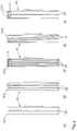
- Figure 4
- different embodiments of a support disc according to the invention.
Figur 1 zeigt eine Prinzipdarstellung einer Lagerung 1 für einen Offenend-Spinnrotor
2, wie sie standardmäßig an Offenend-Spinnmaschinen zum Einsatz
kommt. Die Lagerung 1 besteht im wesentlichen aus einem Lagerbock
11, der die Stützscheibenlager 12 trägt. Die Stützscheibenlager 12 lagern je
eine Welle 13, die ihrerseits an jedem ihrer Enden über eine Preßverbindung
mit einer Stützscheibe 14 verbunden ist. Die Stützscheiben 14 bilden je zwei
Stützscheibenpaare, so daß zwei Keilspalte 141 gebildet werden. Die Stützscheiben
14 tragen den Rotorschaft 21 des Offenend-Spinnrotors 2. Wird
der Offenend-Spinnrotor 2 beispielsweise über einen Tangentialriemen (nicht
gezeigt) angetrieben, rollt er in den Keilspalten 141 an den Stützscheiben 14
ab. Dadurch werden diese in Drehung versetzt. Die Stützscheiben 14 sind
mit einer Reinigungsnut 3 versehen, die bei der Rotation der Stützscheiben
14 mit ihren Kanten 31 entlang der Berührlinie des Rotorschaftes wandert.
Die Reinigungsnut 3 ist in den Belag 143 in Form einer endlosen Nut eingebracht.
Da der Ablauf des Rotorschaftes 21 auf den Stützscheiben 14 nicht
schlupffrei erfolgt, ist gewährleistet, daß die Kante 31 jede Stelle des Rotorschaftes
erreicht und diesen von Ablagerungen reinigt.Figure 1 shows a schematic diagram of a bearing 1 for an open-
Die Wellen 13, die die Stützscheiben aufnehmen und lagern, sind zueinander
nicht parallel, sondern windschief gelagert, so daß auf den Rotorschaft
21 durch die Stützscheiben ein Axialschub ausgeübt wird. Dieser stützt sich
in bekannter Weise an einem Axiallager 101 ab. Dieses kann beispielsweise
als Spurlager ausgebildet sein, oder wie im Ausführungsbeispiel von Figur 1
angedeutet, in Form eines aerostatischen Axiallagers. Durch die Lagerung
des Rotorschaftes 21 in den Keilspalten 141 der Stützscheiben 14 erfolgt
eine relativ hohe Anpressung des Rotorschaftes auf den Belag 143 der
Stützscheiben 14. Dieser Andruck wird dadurch erzeugt, daß der tangential
über den Rotorschaft 21 laufende Tangentialriemen seinerseits mit einer radialen
Kraft auf den Rotorschaft 21 aufgepreßt wird. Dieser Andruck ist erforderlich,
um den Schlupf zwischen dem Tangentialriemen und dem Rotorschaft
21 klein zu halten, so daß der Rotorschaft 21 und mit ihm der von diesem
gelagerte Offenend-Spinnrotor 2 weitgehend verlustfrei angetrieben
werden können. Dieser Anpreßdruck muß vom Belag 143 jeder Stützscheibe
14 aufgenommen werden. Dadurch, daß sich die Stützscheiben drehen und
der Rotorschaft 21 auf diesen abrollt, wird auf den Belag 143 eine wechselnde
Druckkraft ausgeübt, die den Belag 143 beansprucht. Die Beanspruchung
durch die wechselnde Druckkraft führt zu einer Erwärmung des Belages 143,
und damit zu einer thermischen Belastung.The
Neben dieser Art der Beanspruchung des Belages 143 erfolgt zusätzlich ein
ständiges Reiben des Rotorschaftes 21 senkrecht zur Ebene der Stützscheibe
über deren Belag 143. Dies hat seine Ursache in der, wie oben bereits
erwähnt, parallelen Anordnung der beiden Wellen 13 zueinander. Dieses
Reiben der Stützscheiben über den Rotorschaft führt zu einer Belastung der
Oberfläche der Stützscheibe auf mechanische Art und Weise und zusätzlich
über eine dadurch erzeugte Erwärmung des Belages 143. In addition to this type of stress on the covering 143, there is also a
constant rubbing of the
Die in Figur 2 im Schnitt dargestellte Stützscheibe 14 besitzt eine Reinigungsnut
3 im Belag 143. Dieser bildet an seinem Außenumfang die Lauffläche
144 auf der der Rotorschaft 21 abrollt. Die Stützscheibe 14 besteht aus
einem Grundkörper 5, der beispielsweise aus Aluminium, als Spritzgußteil
ausgebildet werden kann, oder auch aus Kunststoff besteht. Die Stützscheibe
14 besitzt in ihrer Mitte eine Bohrung 51, über die sie an der Welle 13
eines Stützscheibenlagers 12 mittels einer Preßpassung befestigt werden
kann (vgl. Figur 1). Im Bereich des Übergangs des Grundkörpers 5 und Belags
143 kann der Außenumfang des Grundkörpers 5 in besonderer, nicht
dargestellter Art, beispielsweise V- oder hammerförmig ausgestaltet sein,
damit eine bessere Haftung zwischen Grundkörper 5 und Belag 143 gewährleistet
werden kann. In günstiger Ausgestaltung ist der Grundkörper 5
dabei so ausgestaltet, daß im Bereich einer Nut im Belag 143, hier der Reinigungsnut
3, eine genügende Dicke des Belages 143 vorhanden ist.The
Die sichere Befestigung des Belages 143 auf dem Grundkörper 5 der Stützscheibe
14 erfolgt aber nicht ausschließlich über eine formschlüssige Verbindung
zwischen Grundkörper 5 und Belag 143, wie dies in Figur 2 beschrieben
ist, sondern auch durch die Haftung des Belages 143 auf dem
Grundkörper 5. Diese Haftung ist bei einer erfindungsgemäß ausgebildeten
Stützscheibe wesentlich höher, als bei Stützscheiben des Standes der
Technik, bei denen der Belag 143 aus Polyurethan gefertigt ist. Der erfindungsgemäße
Belag aus Kautschuk hat von sich aus eine wesentlich höhere
Haftkraft auf dem Grundkörper als Beläge des Standes der Technik. Außerdem
neigt der erfindungsgemäße Stützscheibenbelag aus Kautschuk weniger
zu Lunkern, wodurch seine Haftkraft nochmals verbessert wird.The secure attachment of the covering 143 on the
Durch die vorteilhafte, geringere Neigung Lunker auszubilden ist es durch
einen Belag 143 der Stützscheibe 14 aus Kautschuk, insbesondere aus Nitrilkautschuk,
ermöglicht, den Belag 143 als dünne Schicht auf dem Außenumfang
des Grundkörpers 5 aufzubringen. Due to the advantageous, lower tendency to form blowholes, it is through
a covering 143 of the
Die in Figur 3 dargestellte Stützscheibe 14, deren Darstellung ebenfalls im
Schnitt ausgeführt ist, besitzt einen Grundkörper 5, der eine ebene, zylinderförmige
Fläche am Umfang besitzt, auf dem der Kautschukbelag 143
gemäß der Erfindung aufgebracht ist. Durch die besonderen physikalischen
Eigenschaften des Kautschuks, insbesondere seine günstige Haftkraft, die
erforderlichenfalls durch Haftvermittler und/oder Aufrauhen der Kontaktfläche
noch wesentlich verbessert werden kann, ist es möglich, ohne einen am Außenumfang
profilierten Grundkörper 5, eine sichere Verbindung zwischen
dem Belag 143 und dem Grundkörper 5 auszuführen. Der bei der Stützscheibe
von Figur 3 verwendete Belag 143 besitzt eine mittig über den Umfang
verlaufende Nut 30, die die Aufgabe einer Kühlnut zur Kühlung des
Belages 143 hat. Solche zur Kühlung eingesetzten Nuten sind im Stand der
Technik üblich. Die Dicke des Belages 143, wie er in Figur 3 dargestellt ist,
stellt eine Ausgestaltungsmöglichkeit dar. Je nach Verwendung von verschieden
eingestellten Kautschukbelägen, ist es möglich, die Beläge wesentlich
dünner auszubilden, als dies beispielsweise bei Polyurethan-Belägen
des Standes der Technik erforderlich ist. Dadurch wird vorteilhaft
erreicht, daß der Belag 143 eine geringere Masse erhält, wodurch wiederum
seine Verbindung zum Grundkörper eine wesentlich kleinere Belastung
durch die Fliehkräfte erfährt, wie dies Beläge des Standes der Technik erfahren.
Trotzdem werden mit einem erfindungsgemäßen Belag 143 aus Kautschuk
die erforderlichen Dämpfungseigenschaften zur Dämpfung des Rotorschaftes
während dessen Abrollens erreicht. Durch die Verringerung der
Dicke wird gleichzeitig die durch die Walkarbeit erzeugte Wärme näher hin
zum Grundkörper 5 verlagert, so daß der Wärmeübergang, insbesondere bei
Stützscheibengrundkörpern aus Metall wesentlich verbessert wird. Dies erhöht
ebenfalls die Lebensdauer des Belages 143 und damit der Stützscheibe
14.The
Die günstigen Eigenschaften des Stützscheibenbelag-Werkstoffs ermöglichen
eine weitere Ausgestaltung des Stützscheibenbelages, insbesondere
der Lauffläche 144, da der erfindungsgemäße Belag 143 widerstandsfähiger,
d.h. verschleißfester ist. Dadurch können beispielsweise schmälere Stützscheiben
eingesetzt werden, wodurch vorteilhaft das Lager kleiner baut und
eine geringere Masse hat. Auch eine vorteilhafte Verkleinerung des Durchmessers
der Stützscheiben ist infolge des erfindungsgemäßen Werkstoffs
für die Lauffläche nunmehr möglich.Enable the favorable properties of the support disc covering material
a further embodiment of the support disk covering, in particular
the
In Figur 4 sind verschiedene Ausführungsbeispiele einer jeweils erfindungsgemäßen
Stützscheibe dargestellt. Das Ausführungsbeispiel a zeigt dabei
eine Nut 30 in einem Belag 143, welche bis nahezu an den Grundkörper 5
(gestrichelte Linie) heranreicht. Durch den Zusammenhalt des Belages an
seinem inneren Umfang ist eine besonders stabile Ausführung geschaffen,
da sichdrie nach außen hin zweiteilige Belag an seiner Befestigungsstelle
gegenseitig abstützt.FIG. 4 shows various exemplary embodiments of one in each case according to the invention
Support disc shown. The embodiment a shows
a
In Figur 4b ist eine Stützscheibe 14 dargestellt, welche zwei Nuten 30 in ihrem
Umfang aufweist. Es sind hierdurch drei Stützflächen für den Rotorschaft
durch den Belag 143 geschaffen.FIG. 4b shows a
In Figur 4c sind drei Nuten 30 in dem Stützscheibenbelag 143 angeordnet.
Wie in dem Schnitt der Figur 4c dargestellt, reichen dabei die äußeren zwei
der Nuten 30 weniger tief in die Belagdicke hinein, als die mittlere, dritte Nut
es tut. Die mittlere Nut 30 ist dabei ebenso wie gemäß Figur 4a bis nahe an
den Grundkörper 5 heran in den Belag 143 eingeschnitten.In Figure 4c, three
Figur 4d zeigt Reinigungsnuten 3, welche in axialer Richtung geneigt in dem
Belag 143 angeordnet sind. Hierdurch entsteht eine axiale Kraft auf die Verschmutzung
des Rotorschaftes, wodurch diese nach und nach gelöst wird
und der Rotorschaft in diesem Bereich nahezu schmutzfrei gehalten wird.Figure 4d shows cleaning
In Figur 4e ist eine Stützscheibe 14 dargestellt, welche aus zwei Belägen
143 besteht. Jeder dieser Beläge 143 ist ohne Kontakt mit dem anderen
Belag 143 auf dem Grundkörper 5 der Stützscheibe 14 befestigt. Durch die
Eigenart des Materials des Belags 143 ist eine besonders gute Haftung sogar
bei dieser Ausführung, bei welcher kein oder ggf. nur ein geringer seitlicher
Kontakt mit dem Grundkörper 5 der Stützscheibe 14 vorhanden ist, ausreichend.In Figure 4e, a
Eine erfindungsgemäß ausgebildete Stützscheibenlagerung ist allgemein weniger empfindlich gegenüber Fertigungs- und Montagetoleranzen und ermöglicht dadurch eine kostengünstigere Herstellung. So ist es beispielsweise möglich ohne anschließender seitlicher spanender Bearbeitung den Stützscheibenbelag aufzuspritzen. Zur Feinbearbeitung ist lediglich die Umfangsfläche zu bearbeiten.A support disk bearing designed according to the invention is general less sensitive to manufacturing and assembly tolerances and enables thereby cheaper production. For example possible without subsequent machining of the support disc cover spray on. Only the peripheral surface is for fine machining to edit.
Weitere Vorteile ergeben sich aus den vorteilhaften Werkstoffeigenschaften. So hat der Kautschuk von Natur aus einen geringeren elektrischen Widerstand im Vergleich zum Stützscheibenbelag von Stützscheiben des Standes der Technik.Further advantages result from the advantageous material properties. The rubber naturally has a lower electrical resistance in comparison to the supporting disc covering of supporting discs of the stand of the technique.
Claims (18)
Applications Claiming Priority (2)
| Application Number | Priority Date | Filing Date | Title |
|---|---|---|---|
| DE10018440A DE10018440A1 (en) | 2000-04-13 | 2000-04-13 | Support disc for a support disc bearing for spinning rotors |
| DE10018440 | 2000-04-13 |
Publications (2)
| Publication Number | Publication Date |
|---|---|
| EP1146152A1 true EP1146152A1 (en) | 2001-10-17 |
| EP1146152B1 EP1146152B1 (en) | 2004-12-29 |
Family
ID=7638681
Family Applications (1)
| Application Number | Title | Priority Date | Filing Date |
|---|---|---|---|
| EP01108550A Expired - Lifetime EP1146152B1 (en) | 2000-04-13 | 2001-04-05 | Support disc with a caouchouc ring for a disc bearing holding a spinning rotor |
Country Status (4)
| Country | Link |
|---|---|
| US (1) | US6688775B2 (en) |
| EP (1) | EP1146152B1 (en) |
| AT (1) | ATE286161T1 (en) |
| DE (2) | DE10018440A1 (en) |
Cited By (5)
| Publication number | Priority date | Publication date | Assignee | Title |
|---|---|---|---|---|
| EP1327707A1 (en) * | 2002-01-10 | 2003-07-16 | Rieter Ingolstadt Spinnereimaschinenbau AG | Basic body for the support disk of an OE-rotor bearing |
| DE10230171A1 (en) * | 2002-02-08 | 2003-08-21 | Rieter Ingolstadt Spinnerei | Support disc for the storage of an open-end spinning rotor |
| CN103398094A (en) * | 2013-07-26 | 2013-11-20 | 苏州天华有色金属制品有限公司 | Disk with bidirectional circular sliding chutes |
| CN103518009A (en) * | 2012-05-09 | 2014-01-15 | 后藤义一 | Rotor shaft support disk for open-end spinning frame |
| WO2017194433A1 (en) * | 2016-05-13 | 2017-11-16 | Rieter Ingolstadt Gmbh | Spinning rotor for an open-end spinning machine having a friction-enhancing lining made of an elastomeric material, and open-end spinning machine |
Families Citing this family (4)
| Publication number | Priority date | Publication date | Assignee | Title |
|---|---|---|---|---|
| US6332893B1 (en) * | 1997-12-17 | 2001-12-25 | Myocor, Inc. | Valve to myocardium tension members device and method |
| DE10237007A1 (en) * | 2001-11-29 | 2003-06-12 | Rieter Ingolstadt Spinnerei | Support disc and bearing for a spinning rotor |
| DE102012014660A1 (en) * | 2012-07-24 | 2014-01-30 | Saurer Germany Gmbh & Co. Kg | Support disk storage for an open-end spinning device |
| DE102015104491A1 (en) | 2015-03-25 | 2016-09-29 | Rieter Ingolstadt Gmbh | Spinning rotor with a tread, support disk for supporting a spinning rotor and open-end spinning apparatus with a spinning rotor and a bearing device with support disks |
Citations (2)
| Publication number | Priority date | Publication date | Assignee | Title |
|---|---|---|---|---|
| DE4227489A1 (en) * | 1992-08-20 | 1994-03-10 | Schurr Stahlecker & Grill | Synthetic support wheel for open end spinning rotor bearing - has wheel body moulded into premoulded outer ring to give interlocking profile joint without machining |
| DE19824286A1 (en) * | 1998-05-29 | 1999-12-02 | Rieter Ingolstadt Spinnerei | Bearing for an open-end spinning rotor using support disks |
Family Cites Families (11)
| Publication number | Priority date | Publication date | Assignee | Title |
|---|---|---|---|---|
| DE3324129A1 (en) | 1983-07-05 | 1985-01-17 | Fritz 7347 Bad Überkingen Stahlecker | BEARING AND DRIVE FOR A SPINNING ROTOR OF AN OPEN-END SPINNING DEVICE |
| DE3342768A1 (en) * | 1983-11-25 | 1985-06-05 | Schubert & Salzer Maschinenfabrik Ag, 8070 Ingolstadt | SUPPORT DISC BEARING |
| US5178473A (en) | 1983-11-25 | 1993-01-12 | Schubert & Salzer Maschinenfabrik Aktiengesellschaft | Supporting-disk bearing |
| DE3615777A1 (en) * | 1986-05-10 | 1987-11-12 | Stahlecker Fritz | SUPPORT DISC FOR A SUPPORT DISC BEARING OF A OE SPINNING ROTOR |
| US4892422A (en) * | 1988-08-01 | 1990-01-09 | American Suessen Corporation | Support assembly for the rotor of an open end yarn spinning apparatus |
| DE3826851C2 (en) * | 1988-08-06 | 1996-01-11 | Stahlecker Fritz | Support disc for a support disc bearing of OE spinning rotors |
| US4893946A (en) * | 1989-05-15 | 1990-01-16 | Amkor Industries, Inc. | Roller for spinning frame |
| DE4121387C2 (en) * | 1991-06-28 | 2000-12-14 | Schlafhorst & Co W | Support disc bearing of a rotor spinning device |
| DE19712916A1 (en) * | 1997-03-27 | 1998-10-01 | Novibra Gmbh | Support disc for open-ended spinning rotor |
| DE19845237A1 (en) * | 1998-10-01 | 2000-04-06 | Schlafhorst & Co W | Support disc of a rotor spinning device |
| DE19908922B4 (en) * | 1999-03-02 | 2007-04-19 | Carl Freudenberg Kg | Support disk for the bearing of a rotor |
-
2000
- 2000-04-13 DE DE10018440A patent/DE10018440A1/en not_active Withdrawn
-
2001
- 2001-04-05 DE DE50104923T patent/DE50104923D1/en not_active Expired - Lifetime
- 2001-04-05 AT AT01108550T patent/ATE286161T1/en not_active IP Right Cessation
- 2001-04-05 EP EP01108550A patent/EP1146152B1/en not_active Expired - Lifetime
- 2001-04-11 US US09/833,086 patent/US6688775B2/en not_active Expired - Lifetime
Patent Citations (2)
| Publication number | Priority date | Publication date | Assignee | Title |
|---|---|---|---|---|
| DE4227489A1 (en) * | 1992-08-20 | 1994-03-10 | Schurr Stahlecker & Grill | Synthetic support wheel for open end spinning rotor bearing - has wheel body moulded into premoulded outer ring to give interlocking profile joint without machining |
| DE19824286A1 (en) * | 1998-05-29 | 1999-12-02 | Rieter Ingolstadt Spinnerei | Bearing for an open-end spinning rotor using support disks |
Non-Patent Citations (1)
| Title |
|---|
| J.WEIR & R.C. BERKEY: "Carboxylierter Nitrilkautschuk-Eigenschaften und Anwendung", GUMMI.ASBEST.KUNSTSTOFFE, vol. 36, no. 6, 1983, Stuttgart,Deutschland, pages 268 - 274, XP002173274 * |
Cited By (6)
| Publication number | Priority date | Publication date | Assignee | Title |
|---|---|---|---|---|
| EP1327707A1 (en) * | 2002-01-10 | 2003-07-16 | Rieter Ingolstadt Spinnereimaschinenbau AG | Basic body for the support disk of an OE-rotor bearing |
| DE10230171A1 (en) * | 2002-02-08 | 2003-08-21 | Rieter Ingolstadt Spinnerei | Support disc for the storage of an open-end spinning rotor |
| CN103518009A (en) * | 2012-05-09 | 2014-01-15 | 后藤义一 | Rotor shaft support disk for open-end spinning frame |
| CN103518009B (en) * | 2012-05-09 | 2016-02-03 | 后藤义一 | The armature spindle supporting disk of free end spinning frame |
| CN103398094A (en) * | 2013-07-26 | 2013-11-20 | 苏州天华有色金属制品有限公司 | Disk with bidirectional circular sliding chutes |
| WO2017194433A1 (en) * | 2016-05-13 | 2017-11-16 | Rieter Ingolstadt Gmbh | Spinning rotor for an open-end spinning machine having a friction-enhancing lining made of an elastomeric material, and open-end spinning machine |
Also Published As
| Publication number | Publication date |
|---|---|
| DE10018440A1 (en) | 2001-10-18 |
| US20020025094A1 (en) | 2002-02-28 |
| DE50104923D1 (en) | 2005-02-03 |
| ATE286161T1 (en) | 2005-01-15 |
| US6688775B2 (en) | 2004-02-10 |
| EP1146152B1 (en) | 2004-12-29 |
Similar Documents
| Publication | Publication Date | Title |
|---|---|---|
| EP0144503B1 (en) | Connecting element for two machine parts or structural parts,for example extensible fit screw | |
| WO2006119738A1 (en) | Four-row tapered roller bearing | |
| EP1146152B1 (en) | Support disc with a caouchouc ring for a disc bearing holding a spinning rotor | |
| EP2094983B1 (en) | Radial roller bearing, in particular for storing shafts in wind turbine transmissions | |
| EP0620298B1 (en) | Open-end spinning rotor | |
| EP0541898B1 (en) | Support disc | |
| EP0540818A1 (en) | Support disc | |
| EP0960963A2 (en) | Bearing by means of supporting rollers for an open-end spinning rotor | |
| DE2528485A1 (en) | RELEASE ROLLER | |
| EP1068382B1 (en) | Ring for ring frames and ring twisters | |
| EP0794273B1 (en) | Open-end spinning device | |
| DE2902820A1 (en) | Open=end spinning rotor-shaft - has applied wear-resistant surface at supporting disc zone | |
| EP1096045B1 (en) | Bearing for a spinning rotor in an open-end spinningdevice | |
| WO2016150755A1 (en) | Spinning rotor comprising a lining, supporting disc for bearing a spinning rotor and open-end spinning device comprising a spinning rotor and a bearing device comprising supporting discs | |
| EP0985838B1 (en) | Bearing and method for its manufacturing | |
| DE69531073T2 (en) | locking nut | |
| DE102017130339B4 (en) | Ramp disc for guiding the flow of lubricant in an axial bearing arrangement | |
| DE1685976A1 (en) | Storage for spindles of spinning and twisting machines | |
| DE102016108860A1 (en) | Support disc for a bearing for a shaft of an open-end spinning rotor and storage for a shaft of an open-end spinning rotor | |
| DE10237007A1 (en) | Support disc and bearing for a spinning rotor | |
| WO2017194433A1 (en) | Spinning rotor for an open-end spinning machine having a friction-enhancing lining made of an elastomeric material, and open-end spinning machine | |
| DE10230171A1 (en) | Support disc for the storage of an open-end spinning rotor | |
| DE102011083096A1 (en) | Wheel bearing for motor vehicle, has flange and outer ring that are arranged to form axial stop with respective abutment surfaces where rolling elements are provided between abutment surfaces | |
| DE102019113812A1 (en) | Rolling bearing arrangement for an open-end rotor spinning device | |
| DE10039121A1 (en) | Support disc, for open-ended spinning rotor bearing, comprises support ring with running surface for rotor, with two anchor legs extending from running section |
Legal Events
| Date | Code | Title | Description |
|---|---|---|---|
| PUAI | Public reference made under article 153(3) epc to a published international application that has entered the european phase |
Free format text: ORIGINAL CODE: 0009012 |
|
| AK | Designated contracting states |
Kind code of ref document: A1 Designated state(s): AT BE CH CY DE DK ES FI FR GB GR IE IT LI LU MC NL PT SE TR |
|
| AX | Request for extension of the european patent |
Free format text: AL;LT;LV;MK;RO;SI |
|
| 17P | Request for examination filed |
Effective date: 20011124 |
|
| AKX | Designation fees paid |
Free format text: AT BE CH CY DE DK ES FI FR GB GR IE IT LI LU MC NL PT SE TR |
|
| 17Q | First examination report despatched |
Effective date: 20020830 |
|
| GRAP | Despatch of communication of intention to grant a patent |
Free format text: ORIGINAL CODE: EPIDOSNIGR1 |
|
| GRAS | Grant fee paid |
Free format text: ORIGINAL CODE: EPIDOSNIGR3 |
|
| GRAA | (expected) grant |
Free format text: ORIGINAL CODE: 0009210 |
|
| AK | Designated contracting states |
Kind code of ref document: B1 Designated state(s): AT BE CH CY DE DK ES FI FR GB GR IE IT LI LU MC NL PT SE TR |
|
| PG25 | Lapsed in a contracting state [announced via postgrant information from national office to epo] |
Ref country code: GB Free format text: LAPSE BECAUSE OF FAILURE TO SUBMIT A TRANSLATION OF THE DESCRIPTION OR TO PAY THE FEE WITHIN THE PRESCRIBED TIME-LIMIT Effective date: 20041229 Ref country code: FR Free format text: LAPSE BECAUSE OF FAILURE TO SUBMIT A TRANSLATION OF THE DESCRIPTION OR TO PAY THE FEE WITHIN THE PRESCRIBED TIME-LIMIT Effective date: 20041229 Ref country code: IE Free format text: LAPSE BECAUSE OF FAILURE TO SUBMIT A TRANSLATION OF THE DESCRIPTION OR TO PAY THE FEE WITHIN THE PRESCRIBED TIME-LIMIT Effective date: 20041229 Ref country code: NL Free format text: LAPSE BECAUSE OF FAILURE TO SUBMIT A TRANSLATION OF THE DESCRIPTION OR TO PAY THE FEE WITHIN THE PRESCRIBED TIME-LIMIT Effective date: 20041229 Ref country code: ES Free format text: LAPSE BECAUSE OF FAILURE TO SUBMIT A TRANSLATION OF THE DESCRIPTION OR TO PAY THE FEE WITHIN THE PRESCRIBED TIME-LIMIT Effective date: 20041229 Ref country code: FI Free format text: LAPSE BECAUSE OF FAILURE TO SUBMIT A TRANSLATION OF THE DESCRIPTION OR TO PAY THE FEE WITHIN THE PRESCRIBED TIME-LIMIT Effective date: 20041229 |
|
| REG | Reference to a national code |
Ref country code: GB Ref legal event code: FG4D Free format text: NOT ENGLISH |
|
| REG | Reference to a national code |
Ref country code: CH Ref legal event code: EP |
|
| REG | Reference to a national code |
Ref country code: IE Ref legal event code: FG4D Free format text: GERMAN |
|
| REF | Corresponds to: |
Ref document number: 50104923 Country of ref document: DE Date of ref document: 20050203 Kind code of ref document: P |
|
| PG25 | Lapsed in a contracting state [announced via postgrant information from national office to epo] |
Ref country code: DK Free format text: LAPSE BECAUSE OF FAILURE TO SUBMIT A TRANSLATION OF THE DESCRIPTION OR TO PAY THE FEE WITHIN THE PRESCRIBED TIME-LIMIT Effective date: 20050329 Ref country code: GR Free format text: LAPSE BECAUSE OF FAILURE TO SUBMIT A TRANSLATION OF THE DESCRIPTION OR TO PAY THE FEE WITHIN THE PRESCRIBED TIME-LIMIT Effective date: 20050329 Ref country code: SE Free format text: LAPSE BECAUSE OF FAILURE TO SUBMIT A TRANSLATION OF THE DESCRIPTION OR TO PAY THE FEE WITHIN THE PRESCRIBED TIME-LIMIT Effective date: 20050329 |
|
| PG25 | Lapsed in a contracting state [announced via postgrant information from national office to epo] |
Ref country code: CY Free format text: LAPSE BECAUSE OF FAILURE TO SUBMIT A TRANSLATION OF THE DESCRIPTION OR TO PAY THE FEE WITHIN THE PRESCRIBED TIME-LIMIT Effective date: 20050405 Ref country code: LU Free format text: LAPSE BECAUSE OF NON-PAYMENT OF DUE FEES Effective date: 20050405 |
|
| PG25 | Lapsed in a contracting state [announced via postgrant information from national office to epo] |
Ref country code: BE Free format text: LAPSE BECAUSE OF NON-PAYMENT OF DUE FEES Effective date: 20050430 Ref country code: MC Free format text: LAPSE BECAUSE OF NON-PAYMENT OF DUE FEES Effective date: 20050430 |
|
| NLV1 | Nl: lapsed or annulled due to failure to fulfill the requirements of art. 29p and 29m of the patents act | ||
| GBV | Gb: ep patent (uk) treated as always having been void in accordance with gb section 77(7)/1977 [no translation filed] |
Effective date: 20041229 |
|
| REG | Reference to a national code |
Ref country code: IE Ref legal event code: FD4D |
|
| BERE | Be: lapsed |
Owner name: RIETER INGOLSTADT SPINNEREIMASCHINENBAU A.G. Effective date: 20050430 |
|
| PLBE | No opposition filed within time limit |
Free format text: ORIGINAL CODE: 0009261 |
|
| STAA | Information on the status of an ep patent application or granted ep patent |
Free format text: STATUS: NO OPPOSITION FILED WITHIN TIME LIMIT |
|
| 26N | No opposition filed |
Effective date: 20050930 |
|
| EN | Fr: translation not filed | ||
| BERE | Be: lapsed |
Owner name: *RIETER INGOLSTADT SPINNEREIMASCHINENBAU A.G. Effective date: 20050430 |
|
| PG25 | Lapsed in a contracting state [announced via postgrant information from national office to epo] |
Ref country code: PT Free format text: LAPSE BECAUSE OF NON-PAYMENT OF DUE FEES Effective date: 20050529 |
|
| PGFP | Annual fee paid to national office [announced via postgrant information from national office to epo] |
Ref country code: CH Payment date: 20080428 Year of fee payment: 8 |
|
| PGFP | Annual fee paid to national office [announced via postgrant information from national office to epo] |
Ref country code: AT Payment date: 20090423 Year of fee payment: 9 |
|
| REG | Reference to a national code |
Ref country code: CH Ref legal event code: PL |
|
| PG25 | Lapsed in a contracting state [announced via postgrant information from national office to epo] |
Ref country code: LI Free format text: LAPSE BECAUSE OF NON-PAYMENT OF DUE FEES Effective date: 20090430 Ref country code: CH Free format text: LAPSE BECAUSE OF NON-PAYMENT OF DUE FEES Effective date: 20090430 |
|
| PG25 | Lapsed in a contracting state [announced via postgrant information from national office to epo] |
Ref country code: AT Free format text: LAPSE BECAUSE OF NON-PAYMENT OF DUE FEES Effective date: 20100405 |
|
| PGFP | Annual fee paid to national office [announced via postgrant information from national office to epo] |
Ref country code: DE Payment date: 20170503 Year of fee payment: 17 |
|
| PGFP | Annual fee paid to national office [announced via postgrant information from national office to epo] |
Ref country code: IT Payment date: 20170428 Year of fee payment: 17 |
|
| PGFP | Annual fee paid to national office [announced via postgrant information from national office to epo] |
Ref country code: TR Payment date: 20170404 Year of fee payment: 17 |
|
| REG | Reference to a national code |
Ref country code: DE Ref legal event code: R119 Ref document number: 50104923 Country of ref document: DE |
|
| PG25 | Lapsed in a contracting state [announced via postgrant information from national office to epo] |
Ref country code: DE Free format text: LAPSE BECAUSE OF NON-PAYMENT OF DUE FEES Effective date: 20181101 |
|
| PG25 | Lapsed in a contracting state [announced via postgrant information from national office to epo] |
Ref country code: IT Free format text: LAPSE BECAUSE OF NON-PAYMENT OF DUE FEES Effective date: 20180405 |
|
| PG25 | Lapsed in a contracting state [announced via postgrant information from national office to epo] |
Ref country code: TR Free format text: LAPSE BECAUSE OF NON-PAYMENT OF DUE FEES Effective date: 20180405 |