EP1143472A2 - Elektromagnetisches Schaltgerät, insbesondere Schütz - Google Patents
Elektromagnetisches Schaltgerät, insbesondere Schütz Download PDFInfo
- Publication number
- EP1143472A2 EP1143472A2 EP00122064A EP00122064A EP1143472A2 EP 1143472 A2 EP1143472 A2 EP 1143472A2 EP 00122064 A EP00122064 A EP 00122064A EP 00122064 A EP00122064 A EP 00122064A EP 1143472 A2 EP1143472 A2 EP 1143472A2
- Authority
- EP
- European Patent Office
- Prior art keywords
- module
- drive module
- contact
- side walls
- switching device
- Prior art date
- Legal status (The legal status is an assumption and is not a legal conclusion. Google has not performed a legal analysis and makes no representation as to the accuracy of the status listed.)
- Granted
Links
Images

Classifications
-
- H—ELECTRICITY
- H01—ELECTRIC ELEMENTS
- H01H—ELECTRIC SWITCHES; RELAYS; SELECTORS; EMERGENCY PROTECTIVE DEVICES
- H01H50/00—Details of electromagnetic relays
- H01H50/02—Bases; Casings; Covers
- H01H50/04—Mounting complete relay or separate parts of relay on a base or inside a case
- H01H50/041—Details concerning assembly of relays
- H01H50/042—Different parts are assembled by insertion without extra mounting facilities like screws, in an isolated mounting part, e.g. stack mounting on a coil-support
-
- H—ELECTRICITY
- H01—ELECTRIC ELEMENTS
- H01H—ELECTRIC SWITCHES; RELAYS; SELECTORS; EMERGENCY PROTECTIVE DEVICES
- H01H50/00—Details of electromagnetic relays
- H01H50/02—Bases; Casings; Covers
- H01H50/04—Mounting complete relay or separate parts of relay on a base or inside a case
- H01H50/041—Details concerning assembly of relays
- H01H50/045—Details particular to contactors
-
- H—ELECTRICITY
- H01—ELECTRIC ELEMENTS
- H01H—ELECTRIC SWITCHES; RELAYS; SELECTORS; EMERGENCY PROTECTIVE DEVICES
- H01H50/00—Details of electromagnetic relays
- H01H50/54—Contact arrangements
- H01H50/541—Auxiliary contact devices
-
- H—ELECTRICITY
- H01—ELECTRIC ELEMENTS
- H01H—ELECTRIC SWITCHES; RELAYS; SELECTORS; EMERGENCY PROTECTIVE DEVICES
- H01H50/00—Details of electromagnetic relays
- H01H50/54—Contact arrangements
- H01H50/541—Auxiliary contact devices
- H01H50/545—Self-contained, easily replaceable microswitches
-
- H—ELECTRICITY
- H01—ELECTRIC ELEMENTS
- H01H—ELECTRIC SWITCHES; RELAYS; SELECTORS; EMERGENCY PROTECTIVE DEVICES
- H01H50/00—Details of electromagnetic relays
- H01H50/54—Contact arrangements
- H01H50/546—Contact arrangements for contactors having bridging contacts
Definitions
- the present invention relates to an electromagnetic switching device, in particular Contactor, with at least one movable contact piece and thus interacting fixed contact pieces containing contact module, with a drive module having an electromagnetically actuated armature and with a connecting the anchor with the movable contact pieces, Coupling device arranged between the contact module and the drive module.
- the drive module is a for completed basic module.
- the width of the buildable contact modules always corresponds to a multiple of the module width of an auxiliary switch module and cannot go beyond the width of the drive module.
- are electromagnetic Switchgear built three poles so the majority of the drive modules can only be used in a company for three-pole switching devices. For four-pole contactors or switching devices with one across the width of the drive module protruding contact module, another drive module is required because of the smaller production series with economic disadvantages connected is.
- the object of the present invention is to provide an electromagnetic switching device, in particular to develop a contactor in which regardless of the number of poles and regardless of the larger one usually associated with it Width of the contact module while maintaining all functions of the contactor only drive module can be used and in which the arrangement is economical is advantageous.
- the task is solved in that an im Comparison with the drive module extra wide, on both sides over the width of the Drive module protruding contact module can be placed, the two Side walls of the contact module extended to the full height of the drive module and with an open groove aligned in the stroke direction of the armature are provided and enclose both the contact module and the drive module and the coupling device which is displaceable between the side walls on their sides facing the two side walls into the open grooves engaging driver pin is provided.
- each side wall can be at least one on each side wall for attaching an auxiliary switch provided recess.
- the side attachment an auxiliary switch on the switching device is advantageous by this measure possible.
- the driver pins present on the coupling device are advantageous for coupling the actuation of one to the adjacent one Sidewall mounted auxiliary switch formed on the coupling device. Through the open grooves, the actuator of the auxiliary switch and the driver pin of the coupling device of the switching device interlock. No special design of the auxiliary switch is required, its attachment and operation is the same as with other shooters.
- the side walls can be used for coupling adjacent switching devices have provided undercut edges.
- the extended side walls also serve to couple adjacent switching devices without an intermediate gap with the help of coupling elements inserted in the undercut edges.
- the exploded view shown in Fig.1 shows the parts of an electromagnetic Switchgear, which can be divided into the following groups: Parts of a contact module, parts of a drive module and parts of a coupling device.
- the four-pole contact module contains the housing 1 with four laterally insertable in the housing 1 fixed contact pieces 2 with Extinguishing plates 3 surround and can be connected via the terminals 4.
- the housing 1 of the contact module is covered with a cover 5.
- the Both side walls 6 of the housing 1 of the contact module are on the whole Height of the existing under the contact module, intended for three-pole contactors Drive module extends and thus enclose both the contact module as well as the drive module.
- the side walls 6 are in one Lifting direction of the armature 7 of the drive module aligned open groove 8 Mistake.
- the movable closing contact pieces 9 and the movable opening contacts Contact pieces 10 are laterally in the window-like openings 11 of the Contact bridge carrier 12 inserted and locked there.
- the on the contact bridges upcoming contact pressure springs 13 of the movable opener contact pieces 10 support each on a housing-connected abutment 14, the laterally through the window-like openings 11 of the contact bridge support 12 be pushed through.
- the abutment 14 is located in the housing 1 of the switching device and is held in it by positive connections.
- the contact bridge support 12 and thus also the actuation of the movable Contact pieces 9, 10 are connected to the armature 7 with the aid of the coupling device 15 of the drive module coupled.
- the type of coupling is in EP-A2-0739021 described in more detail.
- the coupling pin 16 is thereby in projections located at the bottom of the coupling device, through the coupling hooks of the contact bridge support 12 and through the bore 17 of the armature 7 encountered.
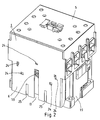
- the coupling device 15 lies between the two side walls 6 of the contact module is slidable and is guided in the housing 1. That are formed on the two side walls 6 facing, in the two open Grooves 8 engaging driver pin 18, as Figure 2 also shows.
- the drive module is housed in a drive housing 19.
- the E core 20 with short-circuit rings 21 are attached to it.
- the switching spring 23 is on in the drive housing 19 attached bobbin 22.
- auxiliary switch can be attached at the Side wall 6 .
- the side walls 6 are provided with recesses 24.
- the side walls 6 are provided with undercut edges 25.
- Generally known coupling members can be in adjacent undercut edges 25 be used.
Landscapes
- Physics & Mathematics (AREA)
- Electromagnetism (AREA)
- Switch Cases, Indication, And Locking (AREA)
- Relay Circuits (AREA)
- Keying Circuit Devices (AREA)
- Elimination Of Static Electricity (AREA)
- Processing And Handling Of Plastics And Other Materials For Molding In General (AREA)
- Treatments Of Macromolecular Shaped Articles (AREA)
Abstract
Description
- Fig.1
- die Explosionszeichnung eines vierpoligen Schützes mit einem für dreipolige Schütze vorgesehenen elektromagnetischen Antriebsmodul und
- Fig.2
- ein vierpoliges Schütz in perspektivischer Darstellung mit einem auf einen Antriebsmodul aufgesetzten überbreiten Kontaktmodul.
Claims (5)
- Elektromagnetisches Schaltgerät, insbesondere Schütz, mit mindestens einem bewegliche Kontaktstücke (9, 10) und damit zusammenwirkende ortsfeste Kontaktstücke (2) enthaltenden Kontaktmodul, mit einem einen elektromagnetisch betätigbaren Anker (7) aufweisenden Antriebsmodul und mit einer den Anker (7) mit den beweglichen Kontaktstücken (9, 10) verbindenden, zwischen dem Kontaktmodul und dem Antriebsmodul angeordneten Ankopplungseinrichtung (15), dadurch gekennzeichnet, dass auf ein Antriebsmodul ein im Vergleich mit dem Antriebsmodul überbreites, beidseitig über die Breite des Antriebsmoduls hinausragendes Kontaktmodul aufsetzbar ist, wobei die beiden Seitenwände (6) des Kontaktmoduls auf die ganze Höhe des Antriebsmoduls verlängert und mit einer in Hubrichtung des Ankers (7) ausgerichteten offenen Nut (8) versehen sind und sowohl das Kontaktmodul als auch das Antriebsmodul umschliessen und die zwischen den Seitenwänden (6) verschiebbare Ankopplungseinrichtung (15) an ihren den beiden Seitenwänden (6) zugekehrten Seiten mit in die offenen Nuten (8) eingreifenden Mitnehmerzapfen (18) versehen ist.
- Elektromagnetisches Schaltgerät nach Anspruch 1, dadurch gekennzeichnet, dass das Antriebsmodul für dreipolige Schütze vorgesehen ist und das Kontaktmodul vierpolig ist.
- Elektromagnetisches Schaltgerät, nach einem der Ansprüche 1 bis 2, dadurch gekennzeichnet, dass an jeder Seitenwand (6) mindestens eine für die Befestigung eines Hilfsschalters vorgesehene Rastausnehmung (24) vorgesehen ist.
- Elektromagnetisches Schaltgerät nach einem der Ansprüche 1 bis 3, dadurch gekennzeichnet, dass die an der Ankopplungseinrichtung (15) vorhandenen Mitnehmerzapfen (18) für die Ankopplung der Betätigung eines an der angrenzenden Seitenwand (6) angebrachten Hilfsschalters an der Ankopplungseinrichtung (15) ausgebildet sind.
- Elektromagnetisches Schaltgerät nach einem der Ansprüche 1 bis 4, dadurch gekennzeichnet, dass die Seitenwände (6) für das Aneinanderkoppeln benachbarter Schaltgeräte vorgesehene Hinterschneidungskanten (25) aufweisen.
Priority Applications (1)
| Application Number | Priority Date | Filing Date | Title |
|---|---|---|---|
| DK00122064T DK1143472T3 (da) | 2000-04-07 | 2000-10-11 | Elektromagnetisk kontaktanordning, især kontaktor |
Applications Claiming Priority (2)
| Application Number | Priority Date | Filing Date | Title |
|---|---|---|---|
| CH6992000 | 2000-04-07 | ||
| CH6992000 | 2000-04-07 |
Publications (3)
| Publication Number | Publication Date |
|---|---|
| EP1143472A2 true EP1143472A2 (de) | 2001-10-10 |
| EP1143472A3 EP1143472A3 (de) | 2003-02-12 |
| EP1143472B1 EP1143472B1 (de) | 2004-12-15 |
Family
ID=4529885
Family Applications (1)
| Application Number | Title | Priority Date | Filing Date |
|---|---|---|---|
| EP00122064A Expired - Lifetime EP1143472B1 (de) | 2000-04-07 | 2000-10-11 | Elektromagnetisches Schaltgerät, insbesondere Schütz |
Country Status (7)
| Country | Link |
|---|---|
| EP (1) | EP1143472B1 (de) |
| JP (1) | JP4460793B2 (de) |
| AT (1) | ATE285118T1 (de) |
| DE (1) | DE50008958D1 (de) |
| DK (1) | DK1143472T3 (de) |
| ES (1) | ES2228377T3 (de) |
| PT (1) | PT1143472E (de) |
Cited By (2)
| Publication number | Priority date | Publication date | Assignee | Title |
|---|---|---|---|---|
| CN111755267A (zh) * | 2020-06-29 | 2020-10-09 | 国网北京市电力公司 | 一种用于充电机直流回路的器件 |
| CN113035646A (zh) * | 2019-12-24 | 2021-06-25 | 施耐德电器工业公司 | 模块化接触器 |
Families Citing this family (1)
| Publication number | Priority date | Publication date | Assignee | Title |
|---|---|---|---|---|
| CN120299952A (zh) * | 2024-01-11 | 2025-07-11 | 上海诺雅克电气有限公司 | 开关装置 |
Family Cites Families (3)
| Publication number | Priority date | Publication date | Assignee | Title |
|---|---|---|---|---|
| US3796978A (en) * | 1972-06-05 | 1974-03-12 | Westinghouse Electric Corp | Electromagnetic contactor with fuse block |
| US4774484A (en) * | 1985-04-09 | 1988-09-27 | Square D Company | Auxiliary electrical contact for electromagnetic contactor |
| US4951018A (en) * | 1989-01-26 | 1990-08-21 | Square D Company | Electromagnetic contactor |
-
2000
- 2000-10-11 ES ES00122064T patent/ES2228377T3/es not_active Expired - Lifetime
- 2000-10-11 EP EP00122064A patent/EP1143472B1/de not_active Expired - Lifetime
- 2000-10-11 AT AT00122064T patent/ATE285118T1/de not_active IP Right Cessation
- 2000-10-11 PT PT00122064T patent/PT1143472E/pt unknown
- 2000-10-11 DK DK00122064T patent/DK1143472T3/da active
- 2000-10-11 DE DE50008958T patent/DE50008958D1/de not_active Expired - Lifetime
-
2001
- 2001-04-05 JP JP2001107637A patent/JP4460793B2/ja not_active Expired - Fee Related
Cited By (3)
| Publication number | Priority date | Publication date | Assignee | Title |
|---|---|---|---|---|
| CN113035646A (zh) * | 2019-12-24 | 2021-06-25 | 施耐德电器工业公司 | 模块化接触器 |
| CN111755267A (zh) * | 2020-06-29 | 2020-10-09 | 国网北京市电力公司 | 一种用于充电机直流回路的器件 |
| CN111755267B (zh) * | 2020-06-29 | 2022-05-17 | 国网北京市电力公司 | 一种用于充电机直流回路的器件 |
Also Published As
| Publication number | Publication date |
|---|---|
| JP4460793B2 (ja) | 2010-05-12 |
| DK1143472T3 (da) | 2005-07-25 |
| EP1143472B1 (de) | 2004-12-15 |
| ATE285118T1 (de) | 2005-01-15 |
| DE50008958D1 (de) | 2005-01-20 |
| EP1143472A3 (de) | 2003-02-12 |
| PT1143472E (pt) | 2005-03-31 |
| JP2001351494A (ja) | 2001-12-21 |
| ES2228377T3 (es) | 2005-04-16 |
Similar Documents
| Publication | Publication Date | Title |
|---|---|---|
| EP0036027A1 (de) | Elektromagnetisches Schütz | |
| EP0185107B1 (de) | Motorschutzschalter | |
| DE69905765T2 (de) | Halbabzweigender elektrischer kontakt | |
| DE3713537C2 (de) | Umkehr-Schaltvorrichtung mit Überstromschutz | |
| DE3734293A1 (de) | Elektromagnetische schaltvorrichtung mit austauschbaren schaltern | |
| EP0287752B1 (de) | Elektromagnetisches Schaltgerät mit elektromagnetischem Antrieb | |
| DE19949565C1 (de) | Schalteinrichtung | |
| WO2006094959A1 (de) | Elektromechanisches schaltgerät | |
| DE4436050C2 (de) | Modul zum Aufbau von Aufzugtableaus | |
| DE2732963C2 (de) | Schütz | |
| EP1143472B1 (de) | Elektromagnetisches Schaltgerät, insbesondere Schütz | |
| DE19617575B4 (de) | Türverriegelung für ein Schaltfeld einer Nieder- oder Mittelspannungsanlage | |
| DE1909460A1 (de) | Magnetisches Steuerrelais | |
| DE1614837C3 (de) | Elektromagnetisches Schütz | |
| EP0452714B1 (de) | Verriegelungsvorrichtung für elektromagnetische Schaltgeräte | |
| DE2702225A1 (de) | Elektrischer schalter mit vertauschbarer ruhe- und arbeitsstellung | |
| EP1869688B1 (de) | Mehrpoliges schaltgerät mit zusatzgehäuse und gegenseitige mechanische verriegelungs vorrichtung | |
| DE69215348T2 (de) | Schaltgeräte für elektromagnetische und manuelle Betätigung | |
| DE2434364C2 (de) | Lastumschalter mit ueberschaltwiderstaenden fuer stufenschalter von stufentransformatoren | |
| DE3508302C2 (de) | ||
| DE69834897T2 (de) | Verwechslungsschutzanordnung für elektrische Schaltgeräte, insbesondere für Leistungsschalter und Differenzstromschutzschalter | |
| DE3409564A1 (de) | Lichtbogenloescheinrichtung | |
| EP1858038B1 (de) | Relais mit Kontaktkraftverstärkung | |
| DE2402236C3 (de) | Steckbares, mit einem quaderförmigen Gehäuse versehenes, elektromagnetisches Relais | |
| DE29615405U1 (de) | Fernantrieb für Niederspannungs-Schutzschalter |
Legal Events
| Date | Code | Title | Description |
|---|---|---|---|
| PUAI | Public reference made under article 153(3) epc to a published international application that has entered the european phase |
Free format text: ORIGINAL CODE: 0009012 |
|
| AK | Designated contracting states |
Kind code of ref document: A2 Designated state(s): AT BE CH CY DE DK ES FI FR GB GR IE IT LI LU MC NL PT SE |
|
| AX | Request for extension of the european patent |
Free format text: AL;LT;LV;MK;RO;SI |
|
| PUAL | Search report despatched |
Free format text: ORIGINAL CODE: 0009013 |
|
| AK | Designated contracting states |
Designated state(s): AT BE CH CY DE DK ES FI FR GB GR IE IT LI LU MC NL PT SE |
|
| AX | Request for extension of the european patent |
Extension state: AL LT LV MK RO SI |
|
| 17P | Request for examination filed |
Effective date: 20030812 |
|
| AKX | Designation fees paid |
Designated state(s): AT BE CH CY DE DK ES FI FR GB GR IE IT LI LU MC NL PT SE |
|
| 17Q | First examination report despatched |
Effective date: 20031031 |
|
| GRAP | Despatch of communication of intention to grant a patent |
Free format text: ORIGINAL CODE: EPIDOSNIGR1 |
|
| GRAS | Grant fee paid |
Free format text: ORIGINAL CODE: EPIDOSNIGR3 |
|
| GRAA | (expected) grant |
Free format text: ORIGINAL CODE: 0009210 |
|
| AK | Designated contracting states |
Kind code of ref document: B1 Designated state(s): AT BE CH CY DE DK ES FI FR GB GR IE IT LI LU MC NL PT SE |
|
| PG25 | Lapsed in a contracting state [announced via postgrant information from national office to epo] |
Ref country code: IE Free format text: LAPSE BECAUSE OF FAILURE TO SUBMIT A TRANSLATION OF THE DESCRIPTION OR TO PAY THE FEE WITHIN THE PRESCRIBED TIME-LIMIT Effective date: 20041215 |
|
| REG | Reference to a national code |
Ref country code: CH Ref legal event code: EP Ref country code: GB Ref legal event code: FG4D Free format text: NOT ENGLISH |
|
| REG | Reference to a national code |
Ref country code: CH Ref legal event code: NV Representative=s name: MORVA PATENTDIENSTE |
|
| GBT | Gb: translation of ep patent filed (gb section 77(6)(a)/1977) |
Effective date: 20041222 |
|
| REG | Reference to a national code |
Ref country code: IE Ref legal event code: FG4D Free format text: GERMAN |
|
| REF | Corresponds to: |
Ref document number: 50008958 Country of ref document: DE Date of ref document: 20050120 Kind code of ref document: P |
|
| REG | Reference to a national code |
Ref country code: SE Ref legal event code: TRGR |
|
| REG | Reference to a national code |
Ref country code: GR Ref legal event code: EP Ref document number: 20050400504 Country of ref document: GR |
|
| REG | Reference to a national code |
Ref country code: PT Ref legal event code: SC4A Free format text: AVAILABILITY OF NATIONAL TRANSLATION Effective date: 20050120 |
|
| REG | Reference to a national code |
Ref country code: ES Ref legal event code: FG2A Ref document number: 2228377 Country of ref document: ES Kind code of ref document: T3 |
|
| REG | Reference to a national code |
Ref country code: DK Ref legal event code: T3 |
|
| REG | Reference to a national code |
Ref country code: IE Ref legal event code: FD4D |
|
| PLBE | No opposition filed within time limit |
Free format text: ORIGINAL CODE: 0009261 |
|
| STAA | Information on the status of an ep patent application or granted ep patent |
Free format text: STATUS: NO OPPOSITION FILED WITHIN TIME LIMIT |
|
| ET | Fr: translation filed | ||
| 26N | No opposition filed |
Effective date: 20050916 |
|
| PGFP | Annual fee paid to national office [announced via postgrant information from national office to epo] |
Ref country code: MC Payment date: 20060320 Year of fee payment: 6 |
|
| PGFP | Annual fee paid to national office [announced via postgrant information from national office to epo] |
Ref country code: AT Payment date: 20060321 Year of fee payment: 6 |
|
| PGFP | Annual fee paid to national office [announced via postgrant information from national office to epo] |
Ref country code: PT Payment date: 20060322 Year of fee payment: 6 |
|
| PGFP | Annual fee paid to national office [announced via postgrant information from national office to epo] |
Ref country code: ES Payment date: 20060327 Year of fee payment: 6 |
|
| PGFP | Annual fee paid to national office [announced via postgrant information from national office to epo] |
Ref country code: SE Payment date: 20060329 Year of fee payment: 6 |
|
| PGFP | Annual fee paid to national office [announced via postgrant information from national office to epo] |
Ref country code: FI Payment date: 20060330 Year of fee payment: 6 |
|
| PGFP | Annual fee paid to national office [announced via postgrant information from national office to epo] |
Ref country code: GR Payment date: 20060331 Year of fee payment: 6 |
|
| PGFP | Annual fee paid to national office [announced via postgrant information from national office to epo] |
Ref country code: LU Payment date: 20060403 Year of fee payment: 6 |
|
| PGFP | Annual fee paid to national office [announced via postgrant information from national office to epo] |
Ref country code: CY Payment date: 20060407 Year of fee payment: 6 |
|
| PGFP | Annual fee paid to national office [announced via postgrant information from national office to epo] |
Ref country code: BE Payment date: 20060428 Year of fee payment: 6 |
|
| PGFP | Annual fee paid to national office [announced via postgrant information from national office to epo] |
Ref country code: NL Payment date: 20060515 Year of fee payment: 7 |
|
| PG25 | Lapsed in a contracting state [announced via postgrant information from national office to epo] |
Ref country code: FI Free format text: LAPSE BECAUSE OF NON-PAYMENT OF DUE FEES Effective date: 20061011 Ref country code: AT Free format text: LAPSE BECAUSE OF NON-PAYMENT OF DUE FEES Effective date: 20061011 |
|
| PG25 | Lapsed in a contracting state [announced via postgrant information from national office to epo] |
Ref country code: SE Free format text: LAPSE BECAUSE OF NON-PAYMENT OF DUE FEES Effective date: 20061012 |
|
| PG25 | Lapsed in a contracting state [announced via postgrant information from national office to epo] |
Ref country code: DK Free format text: LAPSE BECAUSE OF NON-PAYMENT OF DUE FEES Effective date: 20061031 Ref country code: MC Free format text: LAPSE BECAUSE OF NON-PAYMENT OF DUE FEES Effective date: 20061031 |
|
| PG25 | Lapsed in a contracting state [announced via postgrant information from national office to epo] |
Ref country code: PT Free format text: LAPSE BECAUSE OF NON-PAYMENT OF DUE FEES Effective date: 20070411 |
|
| REG | Reference to a national code |
Ref country code: PT Ref legal event code: MM4A Free format text: LAPSE DUE TO NON-PAYMENT OF FEES Effective date: 20070411 |
|
| EUG | Se: european patent has lapsed | ||
| BERE | Be: lapsed |
Owner name: *ROCKWELL AUTOMATION A.G. Effective date: 20061031 |
|
| REG | Reference to a national code |
Ref country code: ES Ref legal event code: FD2A Effective date: 20061013 |
|
| REG | Reference to a national code |
Ref country code: CH Ref legal event code: NV Representative=s name: PATENTANWAELTE SCHAAD, BALASS, MENZL & PARTNER AG |
|
| PG25 | Lapsed in a contracting state [announced via postgrant information from national office to epo] |
Ref country code: ES Free format text: LAPSE BECAUSE OF NON-PAYMENT OF DUE FEES Effective date: 20061013 |
|
| PG25 | Lapsed in a contracting state [announced via postgrant information from national office to epo] |
Ref country code: CY Free format text: LAPSE BECAUSE OF NON-PAYMENT OF DUE FEES Effective date: 20061011 |
|
| NLV4 | Nl: lapsed or anulled due to non-payment of the annual fee |
Effective date: 20080501 |
|
| PG25 | Lapsed in a contracting state [announced via postgrant information from national office to epo] |
Ref country code: LU Free format text: LAPSE BECAUSE OF NON-PAYMENT OF DUE FEES Effective date: 20061011 |
|
| PG25 | Lapsed in a contracting state [announced via postgrant information from national office to epo] |
Ref country code: NL Free format text: LAPSE BECAUSE OF NON-PAYMENT OF DUE FEES Effective date: 20080501 Ref country code: GR Free format text: LAPSE BECAUSE OF NON-PAYMENT OF DUE FEES Effective date: 20070503 |
|
| PG25 | Lapsed in a contracting state [announced via postgrant information from national office to epo] |
Ref country code: BE Free format text: LAPSE BECAUSE OF FAILURE TO SUBMIT A TRANSLATION OF THE DESCRIPTION OR TO PAY THE FEE WITHIN THE PRESCRIBED TIME-LIMIT Effective date: 20061031 |
|
| REG | Reference to a national code |
Ref country code: CH Ref legal event code: PCOW Free format text: NEW ADDRESS: INDUSTRIESTRASSE 20, 5000 AARAU (CH) |
|
| REG | Reference to a national code |
Ref country code: DE Ref legal event code: R082 Ref document number: 50008958 Country of ref document: DE Representative=s name: GRUENECKER PATENT- UND RECHTSANWAELTE PARTG MB, DE |
|
| REG | Reference to a national code |
Ref country code: FR Ref legal event code: PLFP Year of fee payment: 16 |
|
| REG | Reference to a national code |
Ref country code: CH Ref legal event code: NV Representative=s name: PATENTANWAELTE SCHAAD, BALASS, MENZL AND PARTN, CH Ref country code: CH Ref legal event code: PFA Owner name: ROCKWELL AUTOMATION SWITZERLAND GMBH, CH Free format text: FORMER OWNER: ROCKWELL AUTOMATION AG, CH |
|
| REG | Reference to a national code |
Ref country code: FR Ref legal event code: CJ Effective date: 20160705 Ref country code: FR Ref legal event code: CD Owner name: ROCKWELL AUTOMATION SWITZERLAND GMBH Effective date: 20160705 |
|
| REG | Reference to a national code |
Ref country code: FR Ref legal event code: CA Effective date: 20160708 |
|
| REG | Reference to a national code |
Ref country code: FR Ref legal event code: PLFP Year of fee payment: 17 |
|
| REG | Reference to a national code |
Ref country code: DE Ref legal event code: R081 Ref document number: 50008958 Country of ref document: DE Owner name: ROCKWELL AUTOMATION SWITZERLAND GMBH, CH Free format text: FORMER OWNER: ROCKWELL AUTOMATION AG, AARAU, CH Ref country code: DE Ref legal event code: R082 Ref document number: 50008958 Country of ref document: DE Representative=s name: GRUENECKER PATENT- UND RECHTSANWAELTE PARTG MB, DE |
|
| REG | Reference to a national code |
Ref country code: FR Ref legal event code: PLFP Year of fee payment: 18 |
|
| PGFP | Annual fee paid to national office [announced via postgrant information from national office to epo] |
Ref country code: DE Payment date: 20171027 Year of fee payment: 18 Ref country code: FR Payment date: 20171025 Year of fee payment: 18 |
|
| PGFP | Annual fee paid to national office [announced via postgrant information from national office to epo] |
Ref country code: IT Payment date: 20171024 Year of fee payment: 18 Ref country code: CH Payment date: 20171027 Year of fee payment: 18 Ref country code: GB Payment date: 20171027 Year of fee payment: 18 |
|
| REG | Reference to a national code |
Ref country code: DE Ref legal event code: R119 Ref document number: 50008958 Country of ref document: DE |
|
| REG | Reference to a national code |
Ref country code: CH Ref legal event code: PL |
|
| GBPC | Gb: european patent ceased through non-payment of renewal fee |
Effective date: 20181011 |
|
| PG25 | Lapsed in a contracting state [announced via postgrant information from national office to epo] |
Ref country code: DE Free format text: LAPSE BECAUSE OF NON-PAYMENT OF DUE FEES Effective date: 20190501 |
|
| PG25 | Lapsed in a contracting state [announced via postgrant information from national office to epo] |
Ref country code: FR Free format text: LAPSE BECAUSE OF NON-PAYMENT OF DUE FEES Effective date: 20181031 Ref country code: LI Free format text: LAPSE BECAUSE OF NON-PAYMENT OF DUE FEES Effective date: 20181031 Ref country code: CH Free format text: LAPSE BECAUSE OF NON-PAYMENT OF DUE FEES Effective date: 20181031 |
|
| PG25 | Lapsed in a contracting state [announced via postgrant information from national office to epo] |
Ref country code: IT Free format text: LAPSE BECAUSE OF NON-PAYMENT OF DUE FEES Effective date: 20181011 Ref country code: GB Free format text: LAPSE BECAUSE OF NON-PAYMENT OF DUE FEES Effective date: 20181011 |