EP1140657B1 - Recipient de distribution de fluides muni d'un dispositif de regulation de pression - Google Patents
Recipient de distribution de fluides muni d'un dispositif de regulation de pression Download PDFInfo
- Publication number
- EP1140657B1 EP1140657B1 EP99960035A EP99960035A EP1140657B1 EP 1140657 B1 EP1140657 B1 EP 1140657B1 EP 99960035 A EP99960035 A EP 99960035A EP 99960035 A EP99960035 A EP 99960035A EP 1140657 B1 EP1140657 B1 EP 1140657B1
- Authority
- EP
- European Patent Office
- Prior art keywords
- chamber
- pressure
- closing member
- control
- container
- Prior art date
- Legal status (The legal status is an assumption and is not a legal conclusion. Google has not performed a legal analysis and makes no representation as to the accuracy of the status listed.)
- Expired - Lifetime
Links
Images

Classifications
-
- B—PERFORMING OPERATIONS; TRANSPORTING
- B65—CONVEYING; PACKING; STORING; HANDLING THIN OR FILAMENTARY MATERIAL
- B65D—CONTAINERS FOR STORAGE OR TRANSPORT OF ARTICLES OR MATERIALS, e.g. BAGS, BARRELS, BOTTLES, BOXES, CANS, CARTONS, CRATES, DRUMS, JARS, TANKS, HOPPERS, FORWARDING CONTAINERS; ACCESSORIES, CLOSURES, OR FITTINGS THEREFOR; PACKAGING ELEMENTS; PACKAGES
- B65D83/00—Containers or packages with special means for dispensing contents
- B65D83/14—Containers or packages with special means for dispensing contents for delivery of liquid or semi-liquid contents by internal gaseous pressure, i.e. aerosol containers comprising propellant for a product delivered by a propellant
- B65D83/60—Contents and propellant separated
- B65D83/66—Contents and propellant separated first separated, but finally mixed, e.g. in a dispensing head
- B65D83/663—Contents and propellant separated first separated, but finally mixed, e.g. in a dispensing head at least a portion of the propellant being separated from the product and incrementally released by means of a pressure regulator
-
- B—PERFORMING OPERATIONS; TRANSPORTING
- B65—CONVEYING; PACKING; STORING; HANDLING THIN OR FILAMENTARY MATERIAL
- B65D—CONTAINERS FOR STORAGE OR TRANSPORT OF ARTICLES OR MATERIALS, e.g. BAGS, BARRELS, BOTTLES, BOXES, CANS, CARTONS, CRATES, DRUMS, JARS, TANKS, HOPPERS, FORWARDING CONTAINERS; ACCESSORIES, CLOSURES, OR FITTINGS THEREFOR; PACKAGING ELEMENTS; PACKAGES
- B65D7/00—Containers having bodies formed by interconnecting or uniting two or more rigid, or substantially rigid, components made wholly or mainly of metal
- B65D7/02—Containers having bodies formed by interconnecting or uniting two or more rigid, or substantially rigid, components made wholly or mainly of metal characterised by shape
- B65D7/04—Containers having bodies formed by interconnecting or uniting two or more rigid, or substantially rigid, components made wholly or mainly of metal characterised by shape of curved cross-section, e.g. cans of circular or elliptical cross-section
- B65D7/045—Casks, barrels, or drums in their entirety, e.g. beer barrels, i.e. presenting most of the following features like rolling beads, double walls, reinforcing and supporting beads for end walls
-
- B—PERFORMING OPERATIONS; TRANSPORTING
- B67—OPENING, CLOSING OR CLEANING BOTTLES, JARS OR SIMILAR CONTAINERS; LIQUID HANDLING
- B67D—DISPENSING, DELIVERING OR TRANSFERRING LIQUIDS, NOT OTHERWISE PROVIDED FOR
- B67D1/00—Apparatus or devices for dispensing beverages on draught
- B67D1/04—Apparatus utilising compressed air or other gas acting directly or indirectly on beverages in storage containers
- B67D1/0412—Apparatus utilising compressed air or other gas acting directly or indirectly on beverages in storage containers the whole dispensing unit being fixed to the container
- B67D1/0443—Apparatus utilising compressed air or other gas acting directly or indirectly on beverages in storage containers the whole dispensing unit being fixed to the container comprising a gas generator
Definitions
- the invention relates to a container of the type described in the preamble of the main claim.
- Such container is known from EP-0 349 053.
- This known container comprises a pressure capsule having a first, second and third chamber, the first chamber being filled with a pressurised gas to be discharged into the inner space of said container.
- the second and third chamber are positioned, said third chamber being positioned between the first and second chamber.
- An outlet opening is provided between said first and third chamber, provided with a closing member biased in a closed position by a spring.
- the second chamber is separated from the third chamber by a membrane. During operation an operating pressure prevails in the second chamber, moving said membrane depending on the pressure in the third chamber, which during use can freely communicate with the inner space of the container.
- a meltable means is provided for keeping the closing member from being operated by said membrane.
- this is achieved by providing said meltable member in the opening between the third chamber and the environment, after pressurising the third chamber to a pressure above the operating pressure prevailing in the second chamber during use.
- a ring-shaped meltable element is provided around part of the closing member, thereby preventing movement of said closing member before melting said meltable member.
- This known container has the disadvantage that said container has to be heated prior to use, for melting said meltabel member, thereby contaminating the fluid to be dispensed and heating said fluid, which may be undesirable. Furthermore, such container is difficult to assemble and cannot be stored easily over relatively long periods.
- a further container having pressurising means is known from FR-A-2 690 142.
- This known container comprises an inner space in which a fluid to be dispensed is included, which inner space accommodates a pressure vessel with pressure control means.
- a first chamber is formed into which a gas is introduced under relatively high pressure, while an outlet opening is provided which is closed by a closing member.
- This closing member is slightly rod-shaped and is surrounded in the outlet opening by an O-ring which tightly seals thereagainst.
- a circumferential groove is provided in the rod-shaped element.
- a second chamber is formed opposite the first chamber, which second chamber, on the side proximal to the first chamber, is closed by a membrane to which the rod-shaped element is attached by one end thereof.
- a control pressure is created by means of a gas.
- Included between the first and the second chamber is a third chamber through which the rod-shaped element extends and which is provided with an opening forming a fluid connection between the third chamber and the inner space of the container.
- This known container has the drawback that already before the gas is introduced under pressure into the first chamber, the closing member and the control means therefor, in this case the second chamber, the membrane-shaped wall part and the rod-shaped element, must have been fitted.
- the first chamber is filled by pressing gas under particularly high pressure into the third chamber via the opening, such that the membrane-shaped element is deformed in the direction away from the first chamber.
- the gas can then pass this end under high pressure and be introduced into the first chamber.
- the rod-shaped element Upon removal of the high gas pressure, the rod-shaped element will be moved into the outlet opening again under the influence of the control pressure and close said outlet opening.
- the membrane will be held in a relatively highly deformed state for a relatively long time, which is disadvantageous to the elastic properties thereof. Moreover, this entails the risk of a change of the control pressure caused by gas leaking away from the second chamber along or through the highly deformed membrane.
- control pressure may fall out, so that the closure will be lost and the gas from the first chamber will flow freely to the container, as a result of which the container will be subjected to an unduly high pressure.
- a further drawback of this known apparatus is that the rod-shaped body closes the outlet opening of the second chamber by means of an O-ring.
- This O-ring will continuously be subjected to the high gas pressure in the second chamber.
- gas can simply flow away between the rod-shaped element and the O-ring. This, too, will eventually cause the gas to flow away from the first chamber to the container and build up an unduly high pressure therein. This is undesirable, both because of the unduly high pressure build-up and because of the poor functioning of the fluid dispensing operation.
- the object of the invention is to provide a container of the type described in the preamble, in which the drawbacks of the known container are avoided while the advantages thereof are maintained.
- the object of the invention is to provide a container with a pressure control device for maintaining a substantially constant, preset pressure in the container, with the pressure control device enabling simple filling with a pressure fluid and maintaining its pressure-controlling action during relatively long times.
- a container according to the present invention is characterized by the features of claim 1.
- pressure fluid can be received and retained in the first chamber without the control means and/or the second chamber having been fitted.
- the closing member is biased in the closed position and will keep the passage opening closed at all times when the control member, at least the second chamber, has been removed, or at least the pressure-controlling action thereof has been put out of operation.
- the advantage thus achieved is that the control means can be fitted after the first chamber has been filled, while the control means can moreover be stored and transported separately from the first chamber.
- different control means can be applied, depending on, for instance, the desired control pressure, a desired travel of the operating member and the like. This also prevents the closing member from being operated prematurely.
- the closing member can be operated by the control means only after assembly.
- the first chamber is filled along the closing member with gas or another pressure fluid under high pressure, but the first chamber can also be filled prior to the positioning of the closing member.
- an apparatus according to the present invention is characterized by the features of claim 2.
- Positioning the closing member at least substantially on the side of the passage opening facing the first chamber offers the advantage that during use, the closing member will be forced in the direction of the passage opening and against the seating under the influence of the pressure prevailing in the first chamber, so as to close the passage opening.
- limit means which limit the maximum travel of the closing member, the closing member is readily prevented from entering the first chamber loosely.
- the limit means may, for instance, be provided with ribs, slots or passage openings, such that the closing member in a position in which it has moved away from the passage opening can abut against at least a part of said ribs or material present between said slots or openings, while releasing fluid connections between the passage opening and the closing member on the one hand and recesses located between said ribs or the slots or passage openings on the other.
- ribs, slots or openings may be incorporated into a side, facing away from the seating, of the closing member itself.
- biasing means spring means which bias the closing member in the closed position, also when no excess pressure is present in the first chamber. This readily prevents contamination of the inner space of the first chamber, while, moreover, no gases or solid substances can escape therefrom.
- a container according to the present invention is characterized by the features of claim 3.
- the advantage is achieved that the principal direction of movement of the control means will not coincide with the principal direction of movement of the closing member, which creates a greater freedom of design and moreover allows greater tolerances. Indeed, in the case of coinciding principal directions of movement, the position of the second chamber, at least of the control means, will have to be determined particularly accurately with respect to the closing member in at least the closed position.
- a further advantage of such container may be that an unintentional movement of the control means in the principal direction of movement of the closing member will not, or at least not directly, result in a movement of the closing member. Thus, unintentional release of gas is prevented yet more effectively.
- the control means preferably extends at least substantially entirely outside the first chamber, enabling it to be removed in a simple fashion. After all, this does not involve the release of an opening in the first chamber.
- a container according to the present invention is further characterized by the features of claim 5.
- valve as closing member offers the advantage that a closing member biased in the closed position can easily be obtained.
- the advantage achieved by arranging this in such a manner that it can be opened by at least the control means, is that by means of such valve, a self-regulating pressure control device can be obtained in a container according to the present invention.
- a container according to the present invention is characterized by the features of claim 7.
- Detachably connecting the control means to the closing member enables positioning the closing member relative to the control means in a relatively simple manner, while movement of the closing member by the control means can readily be effected.
- a snap connection enables such coupling in a relatively simple manner. Moreover, this may simply prevent detachment of the control means from the closing member, thus preventing malversation.
- a container according to the present invention is characterized by the features of claim 9.
- a container according to the present invention can be obtained in a constructionally simple manner.
- a snap connection enables such coupling in a highly simple manner.
- Such snap connection is preferably of such design that it cannot be detached again without any problem.
- other coupling means can be used as well, for instance bayonet coupling means, screw thread connections or the like.
- a filling opening for the first chamber located at a distance from the passage opening.
- a container according to the invention is characterized by the features of claim 11.
- the advantage achieved is that contact between and mixing of the fluid to be dispensed and the pressure fluid is prevented. This is in particular advantageous when, for instance for toxic or chemical reasons, the pressure fluid must not be dispensed, or at least not together with the fluid to be dispensed.
- the invention further relates to a pressure control device for use in a container according to the invention.
- Such pressure control device according to the invention is preferably characterized by the features of claim 13.
- a relatively simple housing for the first chamber can be obtained with a suitable passage opening.
- the second chamber with the control member can then be placed and coupled to the intermediate part, such that the desired pressure control device is obtained, or at least brought into a condition in which it is ready for use.
- a suitable second chamber with suitable control member can in each case be selected.
- the invention further relates to a method for preparing a container for dispensing a fluid under substantially constant pressure, characterized by the features of claim 14.
- a container which, to a user, is directly ready for use.
- the pressure in the container will in principle decrease.
- an amount of pressure fluid, in particular a gas will thereupon be released from the first chamber to compensate for said pressure decrease.
- the pressure in the inner space of the container is controlled such that it is sufficient for pressing the fluid from the container at a desired pressure.
- the pressure in the inner space at a relatively low level, for instance atmospheric or subatmospheric, while the fluid introduced into the inner space can, for instance, serve as shielding gas or be used to prevent the occurrence of a reduced pressure in the inner space, which, after all, will prevent the fluid from being dispensed or will at least render it more difficult.
- a relatively low level for instance atmospheric or subatmospheric
- the fluid introduced into the inner space can, for instance, serve as shielding gas or be used to prevent the occurrence of a reduced pressure in the inner space, which, after all, will prevent the fluid from being dispensed or will at least render it more difficult.
- the invention moreover relates to the use of a container or a pressure control device according to the invention for dispensing carbonated beverage, in particular beer, under substantially constant pressure, and to the use of a method according to the present invention therefor.
- pressure fluid preferably a gas, in particular CO 2 or CO 2 -containing gas, is used in an apparatus or method according to the invention.
- a pressure fluid may be obtained in a chemical manner, for instance by combining calcium, (bi)carbonate and an acid such as citric acid.
- a pressure gas in particular CO 2
- the (bi)carbonate or another, calcareous product may be included in the third chamber, at least on the opposite side of the closing member.
- the invention will mainly be described with reference to a container having a pressure control device for dispensing beverage, in particular soft drink, more in particular carbonated beverage such as beer, yet it will be understood that with such apparatus, other fluids can be dispensed as well, for instance cosmetic products, foam-forming products, gases and the like.
- reference will mainly be made to the dispensing, under pressure, of a fluid.
- the pressure control device it is also possible to maintain a constant pressure in the container, for instance at the level of the environment of container, for instance to prevent deformation of the container or blocking of the dispensing operation or to protect the contents of the container against contamination from outside.
- identical or corresponding parts have identical or corresponding reference numerals.
- Fig. 1 shows, in highly schematic form, a sectional side elevation of a container 1, in the form of a substantially cylindrical can in which, in the inner space 4 thereof, beverage 2 is included.
- a head space 6 may be present, for instance filled with carbon dioxide.
- a pressure control device 8 comprising a pressure vessel 10, a valve assembly 12 and an outlet opening 14.
- a gas is stored under relatively high pressure in a manner to be described in more detail hereinbelow.
- gas can be introduced, in a manner to be described in more detail hereinbelow, from the pressure vessel 10 into the inner space 4 of the container 1 via the pressure control device 8, for controlling the pressure therein.
- a tap 16 is provided in the sidewall of the container 1, whereby beverage 2 can be discharged from the inner space 4.
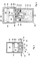
- Fig. 2 shows a pressure control device 8 in a first embodiment, comprising a cylindrical first housing 18 forming the pressure vessel 10 and having, adjacent the top end thereof, a filling opening 20 in which an intermediate part 22 is secured in a manner to be described in more detail hereinbelow.
- a first chamber 24 Formed within the first housing 18 is a first chamber 24, largely filled with activated carbon, for instance activated carbon fiber 26 having a high adsorption and absorption power for the pressure gas, such as CO 2 .
- activated carbon for instance activated carbon fiber 26 having a high adsorption and absorption power for the pressure gas, such as CO 2 .
- activated carbon for instance activated carbon fiber 26 having a high adsorption and absorption power for the pressure gas, such as CO 2 .
- activated carbon for instance activated carbon fiber 26 having a high adsorption and absorption power for the pressure gas, such as CO 2 .
- activated carbon for instance activated carbon fiber 26 having a high adsorption and ab
- another pressure fluid may also be included in the first chamber, for instance a liquid under pressure.
- a reactive substance may also be included in the first chamber, which substance can react with a second reactive substance to form a pressure medium such as CO 2 .
- These may be, for instance, an acid and a calcium product, such as citric acid and (bi)carbonate, while the second reactive component may be stored in the first chamber and reacts only in the case of pressure reduction, or in the third chamber, at least on the side of the closing member remote from the first chamber.
- reaction between the components does not take place until the closing member is temporarily controlled into the open position when the pressure in the inner space of the container is reduced and the components are brought together or undergo sufficient pressure change to form the desired gas.
- Other reactions may be applied in a suitable manner, to be selected depending on, inter alia, the medium to be dispensed.
- the intermediate part 22 comprises a passage opening 28, which is partially closed adjacent its bottom end by an inwardly extending flange 30 provided with a number of bypass openings 32. From the top end, a seating 34 is inserted into the passage opening 28, of which seating 34 the side facing the flange 30 has a convex surface to which an axial bore 36 connects. Between the convex surface 35 and the flange 30, a cavity 38 is formed in which a ball-shaped closing member 40 is movably included, which closing member 40 is biased against the convex surface 35 and the axial bore 36 by biasing means 42 and in said biased position closes the axial bore so as to be gastight and liquidtight.
- the biasing means 42 are designed as a pressure spring supported on the flange 30.
- the intermediate part 22 comprises first coupling means 44 in the form of snap fingers or a snap ring which can be pressed, with deformation, through the filling opening 20 and secured under the longitudinal edge thereof.
- a supporting edge 46 is provided, abutting against the top side of the longitudinal edge of the filling opening 20.
- packing means such as a rubber ring, liquid packing, deforming means or the like, not shown, may be suitably provided, if necessary.
- a second, further coupling means 48 in the form of a longitudinally extending longitudinal edge, parallel to the supporting edge 46.
- countercoupling means 50 of a second housing 52 can be secured.
- This second housing 52 comprises a cylindrical longitudinal wall 54, closed on one side by an end wall 56, while on the opposite side, the countercoupling means 50 are provided in the form of snap fingers or a snap edge or the like.
- a circular membrane 58 Provided within the second housing 52 is a circular membrane 58 whose longitudinal edge is gastightly and liquidtightly secured in the longitudinal wall 54. Between the end wall 56, the longitudinal wall 54 and the membrane 58, a second chamber 60 is confined, of which the membrane 58 constitutes a deformable wall part.
- a third chamber 62 which, via at least one outlet opening 64, is in fluid connection with the inner space 4 of the container 1.
- a rod-shaped control means 66 extends through the axial bore 36 to a position adjacent the closing member 40.
- the control means 66 has its first end secured to the center of the membrane 58, such that upon deformation of the membrane 58, the control means 66 is moved in axial direction.
- the length of the control means 66 is chosen such that at an preselected increase of the volume of the second chamber 60, through deformation of the membrane 58, the free end, distal from the membrane 58, of the control means 66 presses the closing member 40 from the seating 34, allowing gas to flow under pressure via the passage openings 28 and the bypass openings 32, the cavity 38 and the axial bore 36 into the third chamber 62, and from there into the inner space 4 of the container 1 via the outlet opening 64. In this manner, the pressure in the inner space 4 of the container can be increased, for instance in order to bring this pressure to a desired level when beverage has been discharged from the container 1.
- a pressure medium for instance a gas
- control pressure for instance slightly higher than the pressure which is desired in the inner space 4 of the container 1.
- the extent to which this control pressure is higher than the desired pressure for the inner space 4 is substantially determined by the bias produced by the biasing means 42.
- the closing member 40 is pressed back into the closing position against the seating 34.
- gas will be supplied from the first chamber 24 to the inner space, so that pressure control is automatically obtained.
- the membrane may be of a slightly dish-shaped design, with the control pressure in the second chamber 60 corresponding to the primary, desired pressure when the convex side of such membrane 58 faces the second chamber. In such embodiment, an additional pressure difference is required between the second and third chambers to obtain a sufficient displacement of the control means 66 for pushing the closing member 40 from the seating 34.
- the pressure in the third chamber 62 will have to be increased slightly further than in the case where a flat membrane 58 is used, to deform the membrane from its concave shape, viewed from the second chamber 60, back into its convex shape.
- the closing member 40 is open, the pressure in the inner space 4 will be raised to slightly above the desired pressure, while gas will not be fed from the first chamber 24 into the inner space 4 until the pressure in the inner space 4 has dropped below the desired level.
- a combination of, for instance, a gas and another fluid or a gas and a solid can be included as pressure medium, such that the control pressure is related to, for instance, the temperature of the beverage 2 in the container 1.
- the control pressure is related to, for instance, the temperature of the beverage 2 in the container 1.
- an amount of the beverage 2 or a fluid corresponding therewith can be included, while depending on the temperature in the second chamber, gas from the beverage included therein will provide an increase or decrease of pressure in the second chamber.
- gas adsorbing or absorbing means in the second chamber 60, whose adsorption or absorption power depends on, inter alia, the temperature. In this manner, an even better control of the pressure in the inner space 4 can be realized.
- a pressure control device 8 can be used as follows. Via the filling opening 20, an appropriate amount of filling material 26 is introduced into the first chamber 24, for instance activated carbon fibers, activated carbon powder or like gas adsorbing and/or absorbing agents, known from, for instance, EP 5 692 381, which is understood to be incorporated herein by reference. Next, the intermediate part 22 is sealingly secured in the filling opening by the first coupling means 44, after which a filling head (not shown) can be connected to the intermediate part 22, such that gas under pressure can be introduced into the first chamber 24 via the axial bore 36 and along the closing member 40. The gas pressure is so high that the closing member 40 is moved from the seating 34, against the biasing means 42.
- Said filling head may be provided with coupling means comparable with the countercoupling means 50, enabling the filling head to be connected to the second coupling means 48 of the intermediate part. If the gas pressure in the filling head is removed, the closing member 40 will be pressed back against the seating 34 by the biasing means 42 and close the axial bore 36, such that the gas under pressure is trapped in the first chamber 24. Next, preferably directly prior to use, the second chamber 52 can be connected to the intermediate part 22 by the second coupling means 48, in the manner described hereinabove, whereupon the pressure control device is ready for use.
- the closing member 40 is located at a distance below the top surface 68 of the intermediate part 22, preventing the closing member 40 from being pressed from the seating 34 unintentionally.
- the first housing 18 with the intermediate part 22 can, with filled first chamber 24, be stored and transported separately from the second housing 52.
- This offers logistic advantages, while, moreover, gas is readily prevented from escaping from the first chamber 24 unintentionally. Indeed, the pressure control will be initiated only after coupling of the first housing 18 and the second housing 52.
- a suitable second housing 52 can be coupled to the first housing 18, at least the intermediate part 22, depending on, for instance, the desired control pressure.
- a further particular advantage of a pressure control device according to the present invention is that the filling means for introducing the gas into the first chamber 24 can be of relatively simple design, comparable with filling devices for existing aerosol containers and the like. As the gas need not be introduced under pressure via the relatively small outlet opening 64 and the third chamber 62, filling can be performed relatively fast, in particular also because during filling, the control means 66 does not extend into the axial bore.
- Fig. 3 shows a portion of an alternative embodiment of a pressure control device according to the present invention, in which, again, an intermediate part 122 is secured in the filling opening 120 of the first housing 118 by first coupling means 144 and an associated supporting edge 146.
- the second housing 152 is secured on the intermediate part 122.
- a piston 158 is arranged in the second housing 152, which piston is connected to the control means 166.
- the piston comprises an O-ring 170 or a like piston spring, to create a gastightly and liquidtightly closed second chamber 160 on the side of the piston 158 distal from the first chamber 124, with intermediate third chamber 162.
- Fig. 4 shows a second alternative embodiment of a pressure control device according to the invention, in which the first housing 218 is provided, adjacent its top side 219, with external screw thread 221, capable of cooperating with internal screw thread 223, adjacent the bottom end of the second housing 252.
- the second housing 252 is cap-shaped, provided with a cylindrical longitudinal wall 254 and a closed end wall 256.
- a piston 258 with piston spring 270 Accommodated within the second housing 252 is again a piston 258 with piston spring 270, thus dividing the second housing 252 into a second chamber 260 and a third chamber 262.
- adsorbing and/or absorbing material 226 is again included.
- a substantially cylindrical recess 272 extends from the top end 219 of the first housing 218 in the direction of the bottom 274 of the first housing 218, coaxially with the first housing 218.
- the recess 272 is open at the top side, comprises a longitudinal wall 276 and a bottom 278.
- a passage opening 228, Provided in the longitudinal wall 276 is a passage opening 228, comprising an axial bore 236, which bore, on the side remote from the recess, connects to a seating 234.
- spring-shaped biasing means 242 receiving support from, for instance, the inner side of the longitudinal wall of the first housing 218, a substantially ball-shaped closing member 240 is pressed against the seating 234.
- a pin 280 is fixedly connected to the closing member 240 and extends through the axial bore 236 into the recess 272. In the biased position, the closing member 240 is sealingly pressed against the seating 234.
- a filter 282 is provided between the longitudinal wall 276 of the recess 272 and the outer wall of the first housing 218, which filter is permeable to gas, but which prevents the material 226 from reaching the closing member 240 and the passage opening 228.
- a rod-shaped control member 266 extends into the recess 272.
- a disk-shaped pressure element 284 is provided around the control member 266, which pressure element extends parallel to the piston 258 and has a diameter D such that upon axial movement of the control member 266, the pressure element 284 is contacted with the free end of the pin 280.
- gas can flow from the first chamber 224 along the seating 234 and the closing member 240 via the passage opening 280 into the recess 272, which recess connects to or forms part of the third chamber 262. From the third chamber, the gas can flow away via the outlet opening 264.
- Axial movement of the control member 266 is again effected by pressure difference between a control pressure in the second chamber 260 and the pressure in the third chamber 262.
- a spacer ring 286 is included in the recess 272, which spacer ring can guide the control member 266.
- bypass openings 233 may be included for passing the gas.
- the spacer ring 286 preferably has a diameter which approximately corresponds to the inside diameter of the recess 272.
- the spacer ring can move along with the control member 266 or guide it.
- the pressure element it is also possible to design the pressure element with a diameter which is approximately equal to the inside diameter of the recess 272, such that the pressure element simultaneously performs the function of the spacer ring, as a result of which the spacer ring can be left out.
- the first housing 218 is, for instance, screwed with the external screw thread 221 into the filling head of a filling device, whereupon gas is introduced under pressure into the first chamber 224 in the manner described hereinabove.
- the second housing 252 with piston 258 and control member 266 can be screwed onto the first housing 218, after which the pressure control device 208 is ready for use.
- biasing means 242 may also be applied to pressure control devices according to the present invention, for instance resilient fingers, flexible elements or the like.
- the closing member may be partially designed as piston and included in an appropriate cylinder, so that compression of a suitable fluid within the cylinder may provide the desired bias.
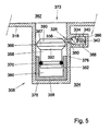
- Fig. 5 shows a portion of a third alternative embodiment of a pressure control device 308 according to the invention, slightly comparable with an embodiment according to Fig. 4.
- a passage opening 328 is again provided, with axial bore 334, in the recess 372 in the first housing 318.
- a closing member 340 is forced against the seating 334, with the pin 380 extending through the axial bore 336 into the recess 372.
- the biasing means 342 and the closing member 340 are accommodated in a fourth chamber 386 with inflow openings 388. This allows the recess 372 to be located at a relatively large distance from the wall of the first housing 218.
- the second housing 352 is accommodated in the recess 372, such that it has its end wall 356 abutting against the bottom 378 of the recess.
- the piston 358 is designed as a cylinder whose outer circumference approximately corresponds to the inner circumference of the second housing 252, with the interposition of an appropriate piston spring 370 or like gastight and liquidtight sealing means. Between the piston 358 and the end wall 356, the second chamber 360 is formed again.
- a control member 366 designed as a disk 367 having frusto-conical longitudinal edges 390, 392.
- the disk 367 has an outside diameter which, for instance, approximately corresponds to the inside diameter of the recess 372, while the smallest section of the frusto-conical longitudinal edges 390, 392 are approximately equal to the section of the piston 358.
- the pin 380 When the piston 358 is in a neutral position, i.e. in a condition in which the pressure in the second chamber 360 is equal to the desired control pressure, the pin 380 has its free end abutting against the outer frusto-conical longitudinal edge 390, preferably adjacent the free end thereof.
- the pressure in the third chamber 362 which in the embodiment shown is formed by the inner space 4 decreases, the piston 358 will be moved upwards by the pressure in the second chamber 360, i.e. in the direction away from the end wall 356.
- the end wall 356 of the second housing 352 has its outer side beveled, such that when the second housing 352 is pressed into the recess 372, it can easily pass the pin 380.
- the second frusto-conical longitudinal edge 392 of the disk 367 has been provided.
- gas can be introduced into the first chamber 324 via the passage opening 328, after which the second housing 352 can be pressed into the recess 372 so as to render the device suitable for use.
- the second housing 252 can be fitted prior to the introduction of the gas into the first chamber 224.
- the piston 358 will have to be secured in a position at which the control pressure prevails in the second chamber 360, also when in the third chamber, at least in the environment of the pressure control device, there prevails a pressure lower than the pressure that is desired in the inner space 4 of the container 1.
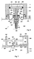
- Fig. 6 shows a portion of a fourth alternative embodiment of a pressure control device 408 according to the invention, comprising a first housing 418, an intermediate part 422 and a second housing 452.
- a valve 494 Accommodated in the intermediate part 422 is a valve 494 of a type which is usually employed in spray cans, such as aerosol containers and the like. Such valve is known from practice.
- Fig. 6 shows a suitable embodiment of a valve 494, yet it will be appreciated that differently designed valves may also be used in a pressure control device according to the present invention.
- the valve comprises a third housing 495 which is fixedly connected to the intermediate part 422 and which contains a fourth chamber 486 including a pressure spring 442 as biasing means.
- a rod-shaped element 496 lies with a collar 498 confined between the coupling part 422 and the top end of the spring 442, and extends beyond the coupling part 422.
- an axial bore 436 in the form of a blind hole.
- a radial bore 437 is provided above the collar 498 .
- the radial bore 437 is closed by a sealing ring 439 in the intermediate part 422.
- the second housing 452 is mounted with appropriate coupling means 448, 450 in the above-described manner, which second housing 452 accommodates a piston 458 for axial displacement.
- the second chamber 460 is separated from the third chamber 462 by the piston 458. Via the outlet opening 464, the third chamber 462 communicates with inner space 4 of the container.
- a cylindrical part 495 is formed having an axial bore 498 which can be fittingly secured over the top end of the rod-shaped element 496.
- a collar 499 is provided in the axial bore 498, which collar receives support from the top end of the rod-shaped element. From the axial bore 498, radial bores 497 extend, which bring the axial bore 498 into fluid connection with the third chamber 462.
- an increase of the volume of the second chamber 460 results in a displacement of the piston 458 in the direction of the first chamber 424, whereby the rod-shaped element 496 is axially displaced in the direction of said first chamber 424, against the bias of the spring 442.
- the fluid connection is obtained between the first chamber 424 and the third chamber 462 via the passage opening 428, the fourth chamber 486, the radial bore 437, the axial bores 436, 498 and the radial bores 497.
- valves 494 known per se or the like
- spray cans aerosol containers and the like, known per se, as part for a pressure control device according to the present invention.
- first chamber 424 can be filled with gas when the second housing 452 with the piston 458 is removed, while the second housing 452 can be fitted in a simple manner.
- Fig. 7. shows a fifth alternative embodiment for a pressure control device according to the present invention, in which the passage opening 528 with the axial bore 536 and the seating 534 are provided in the outer wall of the first housing 518, for instance in the top wall thereof.
- a clamping ring 581 is provided on the pin 580, which extends from the closing member 540 and through the axial bore 536.
- a spring 542 is included as biasing means.
- the second housing 552 is secured on the relevant wall part of the first housing 518, for instance by means of snap fingers 544 suitable therefor or comparable suitable coupling means.
- the first housing 518 comprises a longitudinal wall 554 and an end wall 556, which extends approximately at right angles to the relevant wall parts of the first housing 518.
- the longitudinal wall 554 may, for instance, define a substantially rectangular section of the inner space of the second housing.
- a membrane 558 has its longitudinal edge secured in a manner as described in relation to Fig. 2. From the center of the membrane 558, a control member 556 extends approximately parallel to said wall part of the first housing, through a guide opening 565 in a vertical edge 567 extending from said wall part of the first housing 518. It is thus guaranteed that the control member 566 can move only axially, under the influence of changes of volume of the second chamber 560.
- a frusto-conical pressure element 584 is coaxially secured, having its frusto-conical surface abutting against the free end of the pin 580.
- the frusto-conical pressure element 584 tapers in the direction of the vertical edge 567.
- FIG. 7 An apparatus according to Fig. 7 will enable gas to be introduced into the first chamber 524 via the passage opening 528 when second chamber and control member have been removed.
- the control member 566 Prior to use, the control member 566 is subsequently passed with its first end through the guide opening 565, after which the second housing 552 is coupled to the first housing 518 by means of the snap fingers 544.
- control devices according to the present invention have as an important additional advantage that in the event of a fall-out of the control pressure in the second chamber, for instance due to leakage, the control member is forced into a closed position. This readily and effectively prevents gas from flowing away in an uncontrolled manner from the first chamber to the third chamber to cause an unduly great pressure in the container, at least in the third chamber. Thus, the safety of the container according to the present invention, at least of a pressure control device to be used therewith, is enhanced even further.
- a secondary filling opening may be provided through which gas can be introduced into the first chamber.
- Such secondary filling opening may, for instance, have the advantage that it can be of a relatively large design, so that filling of the first chamber can be realized even more rapidly, while an outlet opening of a suitable, relatively small dimension can be maintained.
- a pressure control device can be secured and positioned in a container in different manners, depending on the use. Also, parts of the pressure control device, in particular the first housing, may form part of the container, for instance as a fixed compartment thereof. Of course, different embodiments as shown may also be combined.
- Biasing means for a device according to the present invention may be arranged separately from the closing member, but may also form an integral part thereof, so that the number of parts required is further reduced. It will be understood that when the pressure in the container is set relatively high, the beverage or any other medium or even, for instance, powder or granular product can be forced from the container via an opening which may be provided in the container in any desired position, for instance in a side or top face. Also, discharge means other than a tap 16 may be used. It will further be understood that the pistons and membranes used in devices according to the present invention may have any desired, suitable shape, for instance round, rectangular or polygonal in section, and may be made from any suitable material, for instance plastic or metal.
- a substantially ball-shaped element is in each case used as closing member.
- differently shaped closing members may be used as well, for instance frusto-conical, disk-shaped and the like.
- the closing member can in each case be positioned in such a manner that the gas pressure in the first chamber will exert an additional pressure on the closing member in the direction of the seating cooperating therewith for increasing the bias.
- the coupling means for a pressure control device according to the present invention may be of reversible design, yet it is preferred that these means cannot be detached without damage, so that they cannot be manipulated in an undesirable manner.
Landscapes
- Engineering & Computer Science (AREA)
- Mechanical Engineering (AREA)
- Chemical & Material Sciences (AREA)
- Dispersion Chemistry (AREA)
- Devices For Dispensing Beverages (AREA)
- Containers And Packaging Bodies Having A Special Means To Remove Contents (AREA)
- Sampling And Sample Adjustment (AREA)
- Feeding, Discharge, Calcimining, Fusing, And Gas-Generation Devices (AREA)
- Coating Apparatus (AREA)
- Loading And Unloading Of Fuel Tanks Or Ships (AREA)
- Infusion, Injection, And Reservoir Apparatuses (AREA)
- Filling Or Discharging Of Gas Storage Vessels (AREA)
- Control Of Fluid Pressure (AREA)
Claims (16)
- Récipient (1) muni d'un dispositif de contrôle de pression (8, 108, 208, 308, 408, 508) pour maintenir une pression sensiblement constante, prédéterminée dans le récipient, ledit récipient (1) étant agencé pour distribuer un fluide, le dispositif de contrôle de pression comprenant une première chambre (24, 124, 224, 324, 424, 524) pour contenir un fluide sous pression, une deuxième chambre (60, 160, 260, 360, 460, 560) dans laquelle une pression de contrôle prévaut et une troisième chambre (62, 162, 262, 362, 462, 562) qui est formée par ou qui communique avec, ou qui est au moins partiellement contenue dans un espace intérieur du récipient (1), tandis qu'entre la première chambre (24, 124, 224, 324, 424, 524) et la troisième chambre (62, 162, 262, 362, 462, 562) est prévue une ouverture de passage (28, 128, 228, 328, 428, 528) contenant un élément de fermeture (40, 140, 240, 340, 440, 540) pour fermer, pendant l'utilisation normale, l'ouverture de passage (28, 128, 228, 328, 428, 528) lorsque la pression dans la troisième chambre (62, 162, 262, 362, 462, 562) est inférieure à la pression de contrôle, un moyen de contrôle (66, 166, 266, 366, 466, 566) étant mobile grâce à une partie déplaçable ou déformable (58, 158, 258, 358, 458, 558) de la paroi de la deuxième chambre (60, 160, 260, 360, 460, 560) et agencé pour déplacer l'élément de fermeture (40, 140, 240, 340, 440, 540) au moins partiellement lorsque la pression dans la troisième chambre (62, 162, 262, 362, 462, 562) est inférieure à la pression d'utilisation, pour permettre au fluide sous pression de s'écouler sous pression depuis la première chambre (24, 124, 224, 324, 424, 524) vers la troisième chambre (62, 162, 262, 362, 462, 562), des moyens de sollicitation étant prévus pour solliciter ledit élément de fermeture dans une position fermée, caractérisé en ce qu'au moins l'élément de contrôle (66) et/ou la deuxième chambre (60, 160, 260, 360, 460, 560) sont au moins partiellement amovibles de la première chambre (24, 124, 224, 324, 424, 524) et lesdits moyens de sollicitation (42, 142, 242, 342, 442, 542) étant prévus pour solliciter l'élément de fermeture (40, 140, 240, 340, 440, 540) dans la position fermée lorsqu'au moins l'élément de contrôle (66, 166, 266, 366, 466, 566) et/ou la deuxième chambre (60, 160, 260, 360, 460, 560) sont au moins partiellement retirés, de telle sorte que la première chambre (24, 124, 224, 324, 424, 524) puisse être remplie tandis que la deuxième chambre (60, 160, 260, 360, 460, 560) et/ou le moyen de contrôle puissent être stockés et transportés séparément de la première chambre (24, 124, 224, 324, 424, 524).
- Récipient selon la revendication 1, dans lequel l'élément de fermeture (40, 140, 240, 340, 440, 540) est positionné au moins sensiblement sur le côté de l'ouverture de passage (28, 128, 228, 328, 428, 528) faisant face à la première chambre (24, 124, 224, 324, 424, 524) et peut fermer l'ouverture de passage (28, 128, 228, 328, 428, 528) en s'appuyant contre une embase autour de l'ouverture de passage (28, 128, 228, 328, 428, 528), des moyens de limitation (32, 132, 232, 332, 432, 532) étant prévus pour limiter le déplacement possible de l'élément de fermeture (40, 140, 240, 340, 440, 540), de telle sorte que lorsque l'élément de fermeture (40, 140, 240, 340, 440, 540) est écarté au maximum de l'ouverture de passage, un fluide puisse être introduit dans la première chambre le long de l'élément de fermeture (40, 140, 240, 340, 440, 540).
- Récipient selon l'une quelconque des revendications précédentes, dans lequel le moyen de contrôle (366, 466, 566) possède une direction principale de mouvement comprenant un angle avec la direction principale de mouvement de l'élément de fermeture (340, 440, 540), ledit angle se trouvant de préférence entre 90 et 175 degrés, plus particulièrement entre 90 et 135 degrés et de préférence autour de 90 degrés.
- Récipient selon l'une quelconque des revendications précédentes, dans lequel la deuxième chambre (60, 160, 260, 360, 460, 560) et le moyen de contrôle (66, 166, 266, 366, 466, 566) sont au moins largement amovibles, l'élément de fermeture dans sa position fermée étant situé au-dessous d'une surface extérieure du dispositif de contrôle de pression de la première chambre (24, 124, 224, 324, 424, 524) dans laquelle l'ouverture de passage (28, 128, 228, 328, 428, 528) est située.
- Récipient selon l'une quelconque des revendications précédentes, dans lequel l'élément de fermeture (440) est conçu comme une partie d'une soupape (494), agencé pour être déplacé d'une position fermée dans une position ouverte à l'aide du moyen de contrôle au moins.
- Récipient selon l'une quelconque des revendications précédentes, dans lequel le moyen de contrôle (266, 366, 566) comprend un élément en forme de tige possédant au moins une partie qui, dans une direction approximativement à angle droit avec l'axe longitudinal de l'élément en question, fait suite à l'extérieur d'une partie attenante, tandis que pendant le mouvement axial de l'élément en forme de tige en question, la partie saillante peut être amenée en contact et hors de contact avec l'élément de fermeture, l'élément de fermeture (240, 340, 540) étant pressé dans la position ouverte lorsque la partie saillante est en contact avec celui-ci et étant forcé dans la position fermée lorsque la partie saillante n'est pas en contact avec celui-ci.
- Récipient selon l'une quelconque des revendications précédentes, dans lequel le moyen de contrôle (40, 140, 240, 340, 440, 540) est relié de manière amovible à l'élément de fermeture, plus particulièrement à l'aide d'un raccordement instantané.
- Récipient selon l'une quelconque des revendications précédentes, dans lequel le moyen de contrôle comprend un élément en forme de membrane (58) qui sollicite l'élément de fermeture (40) dans la position fermée.
- Récipient selon l'une quelconque des revendications précédentes, dans lequel la première chambre (24, 124, 224, 324, 424, 524) est placée dans un premier logement (18, 118, 218, 318, 418, 518), tandis que la deuxième chambre (60, 160, 260, 360, 460, 560) est placée dans un deuxième logement, un moyen d'accouplement (50, 150, 250, 350, 450, 550) étant prévu pour accoupler le premier logement au deuxième logement (52, 152, 252, 352, 452, 552), plus particulièrement un moyen d'accouplement pour former un raccordement instantané.
- Récipient selon la revendication 9, dans lequel le premier logement (18, 119, 218, 318, 418, 518) est en forme de coquille et prévu avec une ouverture de remplissage, le moyen d'accouplement comprenant une partie intermédiaire (22, 122, 222, 322, 422, 522) qui peut être fixée dans ladite ouverture de remplissage et comprend au moins l'élément de fermeture et l'ouverture de passage, la partie intermédiaire (22, 122, 222, 322, 422, 522) comprenant un autre moyen d'accouplement capable de coopérer avec un moyen de contre-accouplement sur le deuxième logement.
- Récipient selon l'une quelconque des revendications précédentes, dans lequel la troisième chambre est au moins sensiblement placée dans un élément en forme de ballon ou dans un élément autrement extensible, de telle sorte que le gaz sortant de la première chambre est reçu dans ledit élément extensible et maintenu séparé du fluide situé dans le récipient et devant être distribué à partir de celui-ci.
- Dispositif de contrôle de pression comprenant une première chambre (24, 124, 224, 324, 424, 524) pour contenir un fluide sous pression, une deuxième chambre (60, 160, 260, 360, 460, 560) dans laquelle une pression de contrôle prévaut et une troisième chambre (62, 162, 262, 362, 462, 562) tandis qu'entre la première chambre (24, 124, 224, 324, 424, 524) et la troisième chambre (62, 162, 262, 362, 462, 562) est prévue une ouverture de passage (28, 128, 228, 328, 428, 528) contenant un élément de fermeture (40, 140, 240, 340, 440, 540) pour fermer, pendant l'utilisation normale, l'ouverture de passage (28, 128, 228, 328, 428, 528) lorsque la pression dans la troisième chambre (62, 162, 262, 362, 462, 562) est inférieure à la pression de contrôle, un moyen de contrôle (66, 166, 266, 366, 466, 566) étant mobile grâce à une partie déplaçable ou déformable (58, 158, 258, 358, 458, 558) de la paroi de la deuxième chambre (60, 160, 260, 360, 460, 560) et agencé pour déplacer l'élément de fermeture (40, 140, 240, 340, 440, 540) au moins partiellement lorsque la pression dans la troisième chambre (62, 162, 262, 362, 462, 562) est inférieure à la pression de contrôle, pour permettre au fluide sous pression de s'écouler sous pression depuis la première chambre (24, 124, 224, 324, 424, 524) jusqu'à la troisième chambre (62, 162, 262, 362, 462, 562), un moyen de sollicitation étant prévu pour solliciter ledit élément de fermeture dans une position fermée, en ce qu'au moins l'élément de contrôle (66) et/ou la deuxième chambre (60, 160, 260, 360, 460, 560) sont au moins partiellement amovibles de la première chambre (24, 124, 224, 324, 424, 524) et ledit moyen de sollicitation (42, 142, 242, 342, 442, 542) étant prévu pour maintenir l'élément de fermeture (40, 140, 240, 340, 440, 540) dans la position fermée lorsqu'au moins l'élément de contrôle (66, 166, 266, 366, 466, 566) et/ou la deuxième chambre (60, 160, 260, 360, 460, 560) sont au moins partiellement retirés, de telle sorte que la première chambre (24, 124, 224, 324, 424, 524) peut être remplie tandis que la deuxième chambre (60, 160, 260, 360, 460, 560) et/ou le moyen de contrôle peuvent être stockés et transportés séparément de la première chambre (24, 124, 224, 324, 424, 524) pour être utilisés dans un récipient selon l'une quelconque des revendications précédentes.
- Dispositif de contrôle de pression, pouvant être relié à ou prévu avec une première chambre pour contenir un fluide sous pression, une deuxième chambre dans laquelle règne une pression de contrôle et une ouverture de passage, pendant l'utilisation située entre la première chambre et l'environnement, tandis que dans l'ouverture de passage un élément de fermeture est inclus pour fermer l'ouverture de passage pendant l'utilisation normale lorsque la pression dans l'environnement est inférieure à la pression de contrôle, un moyen de contrôle étant mobile grâce à une partie déplaçable ou déformable de la paroi de la deuxième chambre et agencé pour déplacer l'élément de fermeture au moins partiellement lorsque la pression dans l'environnement est inférieure à la pression de contrôle, pour permettre au fluide sous pression de s'écouler sous pression à partir de la première chambre jusqu'à l'environnement, le dispositif de contrôle de pression comprenant une partie intermédiaire qui comprend au moins l'ouverture de passage et l'élément de fermeture, ladite partie intermédiaire pouvant être accouplée à une première chambre, au moins l'élément de contrôle et/ou la deuxième chambre étant au moins partiellement amovibles de ladite partie intermédiaire, et un moyen de sollicitation étant prévu pour maintenir l'élément de fermeture dans la position fermée lorsqu'au moins l'élément de contrôle et/ou la deuxième chambre sont au moins partiellement retirés.
- Procédé de préparation d'un récipient pour distribuer un fluide sous une pression sensiblement constante, dans lequel un support on forme de coquille est prévu avec une première partie d'un dispositif de contrôle de pression, ladite première partie comprenant au moins un élément de fermeture qui est sollicité dans une position fermée et qui peut être ouvert par une surpression appliquée sur celui-ci depuis le côté extérieur, dans lequel un fluide sous pression subissant ladite surpression est introduit dans le support le long dudit élément de fermeture sous une pression relativement élevée et dans lequel, lors du retrait de la surpression, l'élément de fermeture est déplacé dans ladite position fermée, après quoi une deuxième partie du dispositif de contrôle de pression est montée sur la première partie, ladite deuxième partie comprenant un moyen de contrôle régulé par une pression de contrôle, ledit moyen de contrôle forçant l'élément de fermeture dans une position ouverte contre ladite sollicitation lorsque dans l'environnement du récipient règne une pression qui est inférieure à ladite pression de contrôle, le support avec les première et deuxième parties accouplées étant inséré dans le récipient, ledit récipient étant rempli avec un fluide devant être distribué et ensuite fermé.
- Utilisation d'un récipient selon l'une quelconque des revendications 1 à 11 ou dispositif de contrôle de pression selon la revendication 12 ou 13 pour distribuer une boisson gazeuse, plus particulièrement de la bière, sous une pression sensiblement constante.
- Utilisation d'un procédé selon la revendication 14 pour préparer un récipient à boisson gazeuse, plus particulièrement de la bière, pour distribuer ladite boisson.
Priority Applications (1)
| Application Number | Priority Date | Filing Date | Title |
|---|---|---|---|
| SI9930193T SI1140657T1 (en) | 1998-12-16 | 1999-12-14 | Container with pressure control device for dispensing fluid |
Applications Claiming Priority (5)
| Application Number | Priority Date | Filing Date | Title |
|---|---|---|---|
| DE29822430U DE29822430U1 (de) | 1998-12-16 | 1998-12-16 | Vorrichtung zum Positionieren einer Hochdruckflasche in Getränkebehältern |
| DE29822430U | 1998-12-16 | ||
| NL1012922A NL1012922C2 (nl) | 1998-12-16 | 1999-08-27 | Container met drukregelinrichting voor fluïdum afgifte. |
| NL1012922 | 1999-08-27 | ||
| PCT/NL1999/000769 WO2000035773A1 (fr) | 1998-12-16 | 1999-12-14 | Recipient de distribution de fluides muni d'un dispositif de regulation de pression |
Publications (2)
| Publication Number | Publication Date |
|---|---|
| EP1140657A1 EP1140657A1 (fr) | 2001-10-10 |
| EP1140657B1 true EP1140657B1 (fr) | 2002-11-27 |
Family
ID=26062087
Family Applications (1)
| Application Number | Title | Priority Date | Filing Date |
|---|---|---|---|
| EP99960035A Expired - Lifetime EP1140657B1 (fr) | 1998-12-16 | 1999-12-14 | Recipient de distribution de fluides muni d'un dispositif de regulation de pression |
Country Status (20)
| Country | Link |
|---|---|
| US (1) | US6412668B1 (fr) |
| EP (1) | EP1140657B1 (fr) |
| JP (1) | JP4558209B2 (fr) |
| CN (1) | CN1131825C (fr) |
| AT (1) | ATE228465T1 (fr) |
| AU (1) | AU765197B2 (fr) |
| BG (1) | BG64440B1 (fr) |
| BR (1) | BR9916337A (fr) |
| CA (1) | CA2355267C (fr) |
| DE (1) | DE69904232T2 (fr) |
| DK (1) | DK1140657T3 (fr) |
| ES (1) | ES2188274T3 (fr) |
| HU (1) | HU225344B1 (fr) |
| NZ (1) | NZ512371A (fr) |
| PL (1) | PL194433B1 (fr) |
| PT (1) | PT1140657E (fr) |
| SI (1) | SI1140657T1 (fr) |
| SK (1) | SK286897B6 (fr) |
| UY (1) | UY25858A1 (fr) |
| WO (1) | WO2000035773A1 (fr) |
Families Citing this family (30)
| Publication number | Priority date | Publication date | Assignee | Title |
|---|---|---|---|---|
| NL1017742C2 (nl) * | 2001-03-30 | 2002-10-03 | Heineken Tech Services | Inrichting en werkwijze voor het aansluiten van een container op een drukbron. |
| FR2829060B1 (fr) * | 2001-09-04 | 2004-09-24 | Vaslin Bucher | Dispositif de securite pour pressoir pneumatique a membrane |
| NL1023968C2 (nl) * | 2003-07-21 | 2005-01-24 | Heineken Tech Services | Drukregelaar voor houder voor koolzuurhoudende drank. |
| NL1023967C2 (nl) * | 2003-07-21 | 2005-01-24 | Heineken Tech Services | Drankafgifte-inrichting met openklapbare afgifteleiding. |
| NL1023969C2 (nl) * | 2003-07-21 | 2005-01-24 | Heineken Tech Services | Samenstel van drankafgifte-inrichting en houder voorzien van een drukmiddelreservoir. |
| DE102004017171A1 (de) † | 2004-04-02 | 2005-10-20 | Huber Verpackungen Gmbh & Co K | Vorrichtung zur Ausgabe eines Fluides aus einem Hohlraum eines Behälters |
| NL1027998C2 (nl) | 2005-01-11 | 2006-07-12 | Heineken Tech Services | Drukregelinrichting voor een container en container voorzien van een dergelijke drukregelinrichting. |
| EP1688813A1 (fr) * | 2005-02-02 | 2006-08-09 | Impress GmbH & Co. oHG | Régulateur de pression avec dispositif de perçage pour cartouche de gas étant montable à l'intérieur de la fermeture d'un fût |
| FR2899210A1 (fr) * | 2006-03-30 | 2007-10-05 | Ad Venta Sarl | Composant pneumatique pour la micro-diffusion controlee de gaz |
| GB2438395B (en) * | 2006-05-26 | 2010-02-24 | John Merlin Copplestone-Bruce | Liquid dispenser |
| ITRN20060041A1 (it) * | 2006-06-23 | 2007-12-24 | Celli Spa | Dispositivo di spillatura e dispositivo di erogazione comprendente tale dispositivo di spillatura |
| NL1032893C2 (nl) * | 2006-11-17 | 2008-05-20 | Heineken Supply Chain Bv | Container voor het afgeven van drank. |
| NL1032892C2 (nl) * | 2006-11-17 | 2008-05-20 | Heineken Supply Chain Bv | Tapinrichting met drukregelmiddelen. |
| DE102007054659A1 (de) * | 2007-11-14 | 2009-05-20 | SCHäFER WERKE GMBH | Verfahren zum Entnehmen von Flüssigkeit aus einem Getränkebehälter und Getränkebehälter |
| US8038039B2 (en) | 2008-05-19 | 2011-10-18 | Millercoors, Llc | Regulated fluid dispensing device and method of dispensing a carbonated beverage |
| US7984845B2 (en) | 2008-05-19 | 2011-07-26 | Millercoors, Llc | Regulated fluid dispensing system packaging |
| US8052012B2 (en) | 2008-05-19 | 2011-11-08 | Millercoors, Llc | Regulated fluid dispensing device and method of dispensing a carbonated beverage |
| US8191740B2 (en) | 2008-05-19 | 2012-06-05 | Millercoors, Llc | Modular constructed regulated fluid dispensing device |
| US8066156B2 (en) * | 2008-05-21 | 2011-11-29 | Millercoors Llc | Beverage dispensing device |
| SG10201405659QA (en) | 2009-07-09 | 2014-11-27 | Advanced Tech Materials | Substantially rigid collapsible liner and flexible gusseted or non-gusseted liners and methods of manufacturing the same and methods for limiting choke-off in liners |
| DE102010030670B4 (de) | 2010-06-29 | 2013-03-07 | Albert-Ludwigs-Universität Freiburg | Verpackung und Gebinde |
| JP6087833B2 (ja) | 2010-11-23 | 2017-03-01 | アドバンスド テクノロジー マテリアルズ,インコーポレイテッド | ライナーベースの分注器 |
| MX2013009376A (es) * | 2011-02-14 | 2014-03-27 | Heineken Supply Chain Bv | Metodo y aparato para el envasado de bebidas bajo presion. |
| WO2012118527A1 (fr) | 2011-03-01 | 2012-09-07 | Advanced Technology Materials, Inc. | Enveloppe externe et garniture interne imbriquées moulées par soufflage et procédés de fabrication de celles-ci |
| NL2009802C2 (en) | 2012-11-13 | 2014-05-14 | Heineken Supply Chain Bv | Container, preform assembly and method and apparatus for forming containers. |
| NL2012981B1 (en) * | 2014-06-11 | 2017-01-17 | Heineken Supply Chain Bv | Beverage dispensing system, beverage container and pressurizing system for use in a beverage dispensing system or container. |
| IL249778B (en) | 2016-12-26 | 2018-04-30 | Hay Dror | A self-carbonating beverage container |
| US10815114B2 (en) | 2016-12-27 | 2020-10-27 | Midnight Madness Distilling, Llc | Effervescent liquid dispenser |
| WO2019023059A1 (fr) | 2017-07-25 | 2019-01-31 | Midnight Madness Distilling, Llc | Distributeur de liquide effervescent |
| NL2023563B1 (en) * | 2019-07-24 | 2021-02-10 | Heineken Supply Chain Bv | Pressure regulating system for a beverage container and beverage container provided therewith |
Family Cites Families (6)
| Publication number | Priority date | Publication date | Assignee | Title |
|---|---|---|---|---|
| US2794579A (en) * | 1954-03-31 | 1957-06-04 | Seaquist Mfg Corp | Aerosol bomb having spaced propellant and dispensable liquids |
| ES2032102T3 (es) * | 1988-06-29 | 1993-01-01 | Jaico C.V. Cooperative Vennootschap | Capsula de presion para un recipiente rociador. |
| BE1003682A3 (nl) * | 1990-02-09 | 1992-05-19 | Jaico Cv | Drukkapsule voor spuitbus en spuitbus die zulke drukkapsule toepast. |
| US5011047A (en) * | 1990-09-05 | 1991-04-30 | I.P.R.S. | Dispensing apparatus |
| FR2689866B1 (fr) | 1992-04-09 | 1994-06-17 | Oreal | Procede pour realiser un melange extemporane d'au moins deux composants, liquides ou pateux, et bidon pressurise pour mettre en óoeuvre un tel procede. |
| FR2690142B1 (fr) | 1992-04-17 | 1995-11-17 | Oreal | Recipient pressurise, en particulier boitier aerosol, pour la distribution sous pression d'un composant liquide ou pateux. |
-
1999
- 1999-12-14 EP EP99960035A patent/EP1140657B1/fr not_active Expired - Lifetime
- 1999-12-14 SK SK847-2001A patent/SK286897B6/sk not_active IP Right Cessation
- 1999-12-14 AU AU16981/00A patent/AU765197B2/en not_active Ceased
- 1999-12-14 CA CA002355267A patent/CA2355267C/fr not_active Expired - Fee Related
- 1999-12-14 PT PT99960035T patent/PT1140657E/pt unknown
- 1999-12-14 WO PCT/NL1999/000769 patent/WO2000035773A1/fr active IP Right Grant
- 1999-12-14 PL PL348820A patent/PL194433B1/pl unknown
- 1999-12-14 CN CN99816092.XA patent/CN1131825C/zh not_active Expired - Fee Related
- 1999-12-14 JP JP2000588048A patent/JP4558209B2/ja not_active Expired - Fee Related
- 1999-12-14 DK DK99960035T patent/DK1140657T3/da active
- 1999-12-14 HU HU0104673A patent/HU225344B1/hu not_active IP Right Cessation
- 1999-12-14 BR BR9916337-3A patent/BR9916337A/pt not_active IP Right Cessation
- 1999-12-14 DE DE69904232T patent/DE69904232T2/de not_active Expired - Lifetime
- 1999-12-14 US US09/868,282 patent/US6412668B1/en not_active Expired - Lifetime
- 1999-12-14 NZ NZ512371A patent/NZ512371A/xx not_active IP Right Cessation
- 1999-12-14 AT AT99960035T patent/ATE228465T1/de active
- 1999-12-14 ES ES99960035T patent/ES2188274T3/es not_active Expired - Lifetime
- 1999-12-14 SI SI9930193T patent/SI1140657T1/xx unknown
- 1999-12-16 UY UY25858A patent/UY25858A1/es unknown
-
2001
- 2001-06-14 BG BG105604A patent/BG64440B1/bg unknown
Also Published As
| Publication number | Publication date |
|---|---|
| PT1140657E (pt) | 2003-04-30 |
| CA2355267C (fr) | 2008-07-29 |
| WO2000035773A1 (fr) | 2000-06-22 |
| CN1334776A (zh) | 2002-02-06 |
| JP4558209B2 (ja) | 2010-10-06 |
| JP2002532348A (ja) | 2002-10-02 |
| UY25858A1 (es) | 2000-08-21 |
| SK8472001A3 (en) | 2001-12-03 |
| SK286897B6 (sk) | 2009-07-06 |
| BG105604A (en) | 2002-02-28 |
| CN1131825C (zh) | 2003-12-24 |
| HU225344B1 (en) | 2006-10-28 |
| BG64440B1 (en) | 2005-02-28 |
| DE69904232D1 (de) | 2003-01-09 |
| US6412668B1 (en) | 2002-07-02 |
| AU1698100A (en) | 2000-07-03 |
| PL194433B1 (pl) | 2007-05-31 |
| CA2355267A1 (fr) | 2000-06-22 |
| DK1140657T3 (da) | 2003-03-24 |
| ES2188274T3 (es) | 2003-06-16 |
| ATE228465T1 (de) | 2002-12-15 |
| DE69904232T2 (de) | 2003-09-04 |
| HUP0104673A2 (hu) | 2002-03-28 |
| HUP0104673A3 (en) | 2002-08-28 |
| SI1140657T1 (en) | 2003-04-30 |
| AU765197B2 (en) | 2003-09-11 |
| PL348820A1 (en) | 2002-06-17 |
| EP1140657A1 (fr) | 2001-10-10 |
| NZ512371A (en) | 2002-12-20 |
| BR9916337A (pt) | 2001-09-11 |
Similar Documents
| Publication | Publication Date | Title |
|---|---|---|
| EP1140657B1 (fr) | Recipient de distribution de fluides muni d'un dispositif de regulation de pression | |
| CA2355262C (fr) | Contenant servant a distribuer du fluide comprenant un dispositif de commande de la pression mis en oeuvre suite a une etape d'activation | |
| KR100597222B1 (ko) | 음료수 용기와 이의 밸브조립체 및 이 음료수 용기를채우거나 비우는 방법 | |
| KR100970825B1 (ko) | 유체 정량토출용 장치 | |
| US4189068A (en) | Perforating and sealing device for carbon dioxide capsules and suchlike | |
| US4756347A (en) | Filling and dispensing valve, adapter and package | |
| US4054526A (en) | Pressurized water treatment bottle | |
| CA2628631C (fr) | Cylindre a source de gaz co2 sous pression | |
| US3558010A (en) | Combination fluid pressure supply and regulator unit | |
| NL1012922C2 (nl) | Container met drukregelinrichting voor fluïdum afgifte. | |
| JPS63272695A (ja) | 流体容器の圧力を除去する装置 | |
| AU639122B2 (en) | Disposable gas generator cartridge | |
| ZA200104766B (en) | Container with pressure control device for dispensing fluid. | |
| MXPA01005969A (en) | Container with pressure control device for dispensing fluid | |
| JPS62208380A (ja) | バルブアセンブリおよびバルブアセンブリに使用するアダプタ | |
| MXPA01006053A (es) | Recipiente para distribuir fluido que comprende un dispositivo de control de presion con etapa de activacion | |
| Oberhofer et al. | Vessel having CO 2 compressed gas source |
Legal Events
| Date | Code | Title | Description |
|---|---|---|---|
| PUAI | Public reference made under article 153(3) epc to a published international application that has entered the european phase |
Free format text: ORIGINAL CODE: 0009012 |
|
| 17P | Request for examination filed |
Effective date: 20010716 |
|
| AK | Designated contracting states |
Kind code of ref document: A1 Designated state(s): AT BE CH CY DE DK ES FI FR GB GR IE IT LI LU MC NL PT SE |
|
| AX | Request for extension of the european patent |
Free format text: AL PAYMENT 20010716;LT PAYMENT 20010716;LV PAYMENT 20010716;MK PAYMENT 20010716;RO PAYMENT 20010716;SI PAYMENT 20010716 |
|
| GRAG | Despatch of communication of intention to grant |
Free format text: ORIGINAL CODE: EPIDOS AGRA |
|
| 17Q | First examination report despatched |
Effective date: 20020306 |
|
| GRAG | Despatch of communication of intention to grant |
Free format text: ORIGINAL CODE: EPIDOS AGRA |
|
| GRAH | Despatch of communication of intention to grant a patent |
Free format text: ORIGINAL CODE: EPIDOS IGRA |
|
| GRAH | Despatch of communication of intention to grant a patent |
Free format text: ORIGINAL CODE: EPIDOS IGRA |
|
| GRAA | (expected) grant |
Free format text: ORIGINAL CODE: 0009210 |
|
| AK | Designated contracting states |
Kind code of ref document: B1 Designated state(s): AT BE CH CY DE DK ES FI FR GB GR IE IT LI LU MC NL PT SE |
|
| AX | Request for extension of the european patent |
Free format text: AL PAYMENT 20010716;LT PAYMENT 20010716;LV PAYMENT 20010716;MK PAYMENT 20010716;RO PAYMENT 20010716;SI PAYMENT 20010716 |
|
| REF | Corresponds to: |
Ref document number: 228465 Country of ref document: AT Date of ref document: 20021215 Kind code of ref document: T |
|
| REG | Reference to a national code |
Ref country code: GB Ref legal event code: FG4D |
|
| REG | Reference to a national code |
Ref country code: CH Ref legal event code: EP |
|
| REG | Reference to a national code |
Ref country code: IE Ref legal event code: FG4D |
|
| REF | Corresponds to: |
Ref document number: 69904232 Country of ref document: DE Date of ref document: 20030109 |
|
| REG | Reference to a national code |
Ref country code: CH Ref legal event code: NV Representative=s name: R. A. EGLI & CO. PATENTANWAELTE |
|
| REG | Reference to a national code |
Ref country code: DK Ref legal event code: T3 |
|
| REG | Reference to a national code |
Ref country code: GR Ref legal event code: EP Ref document number: 20030400591 Country of ref document: GR |
|
| REG | Reference to a national code |
Ref country code: PT Ref legal event code: SC4A Free format text: AVAILABILITY OF NATIONAL TRANSLATION Effective date: 20030221 |
|
| REG | Reference to a national code |
Ref country code: ES Ref legal event code: FG2A Ref document number: 2188274 Country of ref document: ES Kind code of ref document: T3 |
|
| ET | Fr: translation filed | ||
| PLBE | No opposition filed within time limit |
Free format text: ORIGINAL CODE: 0009261 |
|
| STAA | Information on the status of an ep patent application or granted ep patent |
Free format text: STATUS: NO OPPOSITION FILED WITHIN TIME LIMIT |
|
| 26N | No opposition filed |
Effective date: 20030828 |
|
| REG | Reference to a national code |
Ref country code: SI Ref legal event code: IF |
|
| PG25 | Lapsed in a contracting state [announced via postgrant information from national office to epo] |
Ref country code: IT Free format text: LAPSE BECAUSE OF NON-PAYMENT OF DUE FEES;WARNING: LAPSES OF ITALIAN PATENTS WITH EFFECTIVE DATE BEFORE 2007 MAY HAVE OCCURRED AT ANY TIME BEFORE 2007. THE CORRECT EFFECTIVE DATE MAY BE DIFFERENT FROM THE ONE RECORDED. Effective date: 20051214 |
|
| PGFP | Annual fee paid to national office [announced via postgrant information from national office to epo] |
Ref country code: LU Payment date: 20051216 Year of fee payment: 7 |
|
| PGFP | Annual fee paid to national office [announced via postgrant information from national office to epo] |
Ref country code: MC Payment date: 20051228 Year of fee payment: 7 |
|
| PG25 | Lapsed in a contracting state [announced via postgrant information from national office to epo] |
Ref country code: MC Free format text: LAPSE BECAUSE OF NON-PAYMENT OF DUE FEES Effective date: 20061231 |
|
| PG25 | Lapsed in a contracting state [announced via postgrant information from national office to epo] |
Ref country code: CY Free format text: LAPSE BECAUSE OF NON-PAYMENT OF DUE FEES Effective date: 20061214 |
|
| PGFP | Annual fee paid to national office [announced via postgrant information from national office to epo] |
Ref country code: CY Payment date: 20051214 Year of fee payment: 7 |
|
| PG25 | Lapsed in a contracting state [announced via postgrant information from national office to epo] |
Ref country code: LU Free format text: LAPSE BECAUSE OF NON-PAYMENT OF DUE FEES Effective date: 20061214 |
|
| PGRI | Patent reinstated in contracting state [announced from national office to epo] |
Ref country code: IT Effective date: 20091201 |
|
| LTLA | Lt: lapse of european patent or patent extension |
Effective date: 20101214 |
|
| REG | Reference to a national code |
Ref country code: SI Ref legal event code: KO00 Effective date: 20110801 |
|
| PGFP | Annual fee paid to national office [announced via postgrant information from national office to epo] |
Ref country code: CH Payment date: 20131219 Year of fee payment: 15 Ref country code: DE Payment date: 20131220 Year of fee payment: 15 Ref country code: GB Payment date: 20131219 Year of fee payment: 15 Ref country code: DK Payment date: 20131219 Year of fee payment: 15 Ref country code: SE Payment date: 20131219 Year of fee payment: 15 Ref country code: IE Payment date: 20131230 Year of fee payment: 15 Ref country code: PT Payment date: 20130617 Year of fee payment: 15 Ref country code: AT Payment date: 20131211 Year of fee payment: 15 |
|
| PGFP | Annual fee paid to national office [announced via postgrant information from national office to epo] |
Ref country code: FI Payment date: 20131211 Year of fee payment: 15 Ref country code: NL Payment date: 20131219 Year of fee payment: 15 Ref country code: IT Payment date: 20131219 Year of fee payment: 15 Ref country code: ES Payment date: 20131220 Year of fee payment: 15 Ref country code: GR Payment date: 20131212 Year of fee payment: 15 |
|
| PGFP | Annual fee paid to national office [announced via postgrant information from national office to epo] |
Ref country code: BE Payment date: 20131219 Year of fee payment: 15 |
|
| PGFP | Annual fee paid to national office [announced via postgrant information from national office to epo] |
Ref country code: FR Payment date: 20131220 Year of fee payment: 15 |
|
| REG | Reference to a national code |
Ref country code: PT Ref legal event code: MM4A Free format text: LAPSE DUE TO NON-PAYMENT OF FEES Effective date: 20150615 |
|
| PG25 | Lapsed in a contracting state [announced via postgrant information from national office to epo] |
Ref country code: BE Free format text: LAPSE BECAUSE OF NON-PAYMENT OF DUE FEES Effective date: 20141231 |
|
| REG | Reference to a national code |
Ref country code: DE Ref legal event code: R119 Ref document number: 69904232 Country of ref document: DE |
|
| REG | Reference to a national code |
Ref country code: DK Ref legal event code: EBP Effective date: 20141231 |
|
| REG | Reference to a national code |
Ref country code: NL Ref legal event code: V1 Effective date: 20150701 |
|
| REG | Reference to a national code |
Ref country code: NL Ref legal event code: V1 Effective date: 20150701 |
|
| PG25 | Lapsed in a contracting state [announced via postgrant information from national office to epo] |
Ref country code: FI Free format text: LAPSE BECAUSE OF NON-PAYMENT OF DUE FEES Effective date: 20141214 Ref country code: PT Free format text: LAPSE BECAUSE OF NON-PAYMENT OF DUE FEES Effective date: 20150615 Ref country code: SE Free format text: LAPSE BECAUSE OF NON-PAYMENT OF DUE FEES Effective date: 20141215 |
|
| REG | Reference to a national code |
Ref country code: CH Ref legal event code: PL |
|
| REG | Reference to a national code |
Ref country code: SE Ref legal event code: EUG |
|
| REG | Reference to a national code |
Ref country code: AT Ref legal event code: MM01 Ref document number: 228465 Country of ref document: AT Kind code of ref document: T Effective date: 20141214 |
|
| GBPC | Gb: european patent ceased through non-payment of renewal fee |
Effective date: 20141214 |
|
| REG | Reference to a national code |
Ref country code: GR Ref legal event code: ML Ref document number: 20030400591 Country of ref document: GR Effective date: 20150722 |
|
| REG | Reference to a national code |
Ref country code: IE Ref legal event code: MM4A |
|
| REG | Reference to a national code |
Ref country code: FR Ref legal event code: ST Effective date: 20150831 |
|
| PG25 | Lapsed in a contracting state [announced via postgrant information from national office to epo] |
Ref country code: NL Free format text: LAPSE BECAUSE OF NON-PAYMENT OF DUE FEES Effective date: 20150701 |
|
| PG25 | Lapsed in a contracting state [announced via postgrant information from national office to epo] |
Ref country code: DE Free format text: LAPSE BECAUSE OF NON-PAYMENT OF DUE FEES Effective date: 20150701 Ref country code: IE Free format text: LAPSE BECAUSE OF NON-PAYMENT OF DUE FEES Effective date: 20141214 Ref country code: LI Free format text: LAPSE BECAUSE OF NON-PAYMENT OF DUE FEES Effective date: 20141231 Ref country code: GB Free format text: LAPSE BECAUSE OF NON-PAYMENT OF DUE FEES Effective date: 20141214 Ref country code: CH Free format text: LAPSE BECAUSE OF NON-PAYMENT OF DUE FEES Effective date: 20141231 |
|
| PG25 | Lapsed in a contracting state [announced via postgrant information from national office to epo] |
Ref country code: GR Free format text: LAPSE BECAUSE OF NON-PAYMENT OF DUE FEES Effective date: 20150722 Ref country code: FR Free format text: LAPSE BECAUSE OF NON-PAYMENT OF DUE FEES Effective date: 20141231 Ref country code: AT Free format text: LAPSE BECAUSE OF NON-PAYMENT OF DUE FEES Effective date: 20141214 |
|
| PG25 | Lapsed in a contracting state [announced via postgrant information from national office to epo] |
Ref country code: IT Free format text: LAPSE BECAUSE OF NON-PAYMENT OF DUE FEES Effective date: 20141214 |
|
| PG25 | Lapsed in a contracting state [announced via postgrant information from national office to epo] |
Ref country code: DK Free format text: LAPSE BECAUSE OF NON-PAYMENT OF DUE FEES Effective date: 20141231 |
|
| REG | Reference to a national code |
Ref country code: ES Ref legal event code: FD2A Effective date: 20160129 |
|
| PG25 | Lapsed in a contracting state [announced via postgrant information from national office to epo] |
Ref country code: ES Free format text: LAPSE BECAUSE OF NON-PAYMENT OF DUE FEES Effective date: 20141215 |