EP1137099A2 - Connecteur d'antenne - Google Patents
Connecteur d'antenne Download PDFInfo
- Publication number
- EP1137099A2 EP1137099A2 EP01301845A EP01301845A EP1137099A2 EP 1137099 A2 EP1137099 A2 EP 1137099A2 EP 01301845 A EP01301845 A EP 01301845A EP 01301845 A EP01301845 A EP 01301845A EP 1137099 A2 EP1137099 A2 EP 1137099A2
- Authority
- EP
- European Patent Office
- Prior art keywords
- antenna
- circuit board
- printed circuit
- antenna connector
- holding
- Prior art date
- Legal status (The legal status is an assumption and is not a legal conclusion. Google has not performed a legal analysis and makes no representation as to the accuracy of the status listed.)
- Granted
Links
- 239000000523 sample Substances 0.000 claims description 17
- 238000004891 communication Methods 0.000 claims description 12
- 238000012360 testing method Methods 0.000 claims description 12
- 238000000034 method Methods 0.000 claims description 3
- 230000001413 cellular effect Effects 0.000 description 3
- 230000000694 effects Effects 0.000 description 2
- 230000006870 function Effects 0.000 description 2
- 238000005259 measurement Methods 0.000 description 2
- 238000005476 soldering Methods 0.000 description 2
- 210000003813 thumb Anatomy 0.000 description 2
- 238000010276 construction Methods 0.000 description 1
- 238000013461 design Methods 0.000 description 1
- 238000011161 development Methods 0.000 description 1
- 230000009977 dual effect Effects 0.000 description 1
- 238000012423 maintenance Methods 0.000 description 1
- 230000015654 memory Effects 0.000 description 1
- 239000002184 metal Substances 0.000 description 1
- 230000002093 peripheral effect Effects 0.000 description 1
- 230000004044 response Effects 0.000 description 1
- 229910000679 solder Inorganic materials 0.000 description 1
Images


Classifications
-
- H—ELECTRICITY
- H01—ELECTRIC ELEMENTS
- H01Q—ANTENNAS, i.e. RADIO AERIALS
- H01Q1/00—Details of, or arrangements associated with, antennas
- H01Q1/08—Means for collapsing antennas or parts thereof
- H01Q1/088—Quick-releasable antenna elements
-
- H—ELECTRICITY
- H01—ELECTRIC ELEMENTS
- H01Q—ANTENNAS, i.e. RADIO AERIALS
- H01Q1/00—Details of, or arrangements associated with, antennas
- H01Q1/12—Supports; Mounting means
- H01Q1/22—Supports; Mounting means by structural association with other equipment or articles
- H01Q1/24—Supports; Mounting means by structural association with other equipment or articles with receiving set
- H01Q1/241—Supports; Mounting means by structural association with other equipment or articles with receiving set used in mobile communications, e.g. GSM
- H01Q1/242—Supports; Mounting means by structural association with other equipment or articles with receiving set used in mobile communications, e.g. GSM specially adapted for hand-held use
- H01Q1/243—Supports; Mounting means by structural association with other equipment or articles with receiving set used in mobile communications, e.g. GSM specially adapted for hand-held use with built-in antennas
-
- H—ELECTRICITY
- H01—ELECTRIC ELEMENTS
- H01Q—ANTENNAS, i.e. RADIO AERIALS
- H01Q1/00—Details of, or arrangements associated with, antennas
- H01Q1/36—Structural form of radiating elements, e.g. cone, spiral, umbrella; Particular materials used therewith
- H01Q1/38—Structural form of radiating elements, e.g. cone, spiral, umbrella; Particular materials used therewith formed by a conductive layer on an insulating support
Definitions
- the invention relates to an antenna connector for holding an antenna and a printed circuit board in relation to each other so that there is contact between the antenna and the printed circuit board.
- Electronic devices e.g. mobile telephones
- These electronic devices have a printed circuit board, whereon electronic components are mounted during a pick and place process.
- An object of the invention is to provide an antenna connector that enables that measurements for controlling the characteristics of a radio part on a printed circuit board can easily be conducted without breaking the antenna and that the components mounted beneath the antenna can on a later occasion be reached for repairing or checking without breaking the antenna.
- an antenna connector for holding an antenna in relation to a printed circuit board, where the antenna connector has means for releasable holding of the antenna onto the printed circuit board and that the holding means of the antenna connector are constructed to enable later flexible removal of the antenna.
- An object of the invention is to provide a communication unit having a printed circuit board provided with an antenna connector for holding an antenna in relation to a printed circuit board, enabling easy removal of the antenna and availability to components mounted beneath the antenna.
- a communication unit provided with an antenna connector for holding an antenna in relation to a printed circuit board, where the antenna connector has means for releasable holding of the antenna onto the printed circuit board, and that the holding means of the antenna connector are constructed to enable later flexible removal of the antenna.
- the antenna connector according to the invention will be described with reference to a hand portable phone, preferably a cellular/mobile phone.
- a hand portable phone preferably a cellular/mobile phone.
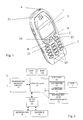
- a preferred embodiment of this phone is shown in fig. 1, where a phone is shown in perspective.
- the phone is provided with a front cover 2 having a window frame 3 encircling the protection window of the display assembly 1.
- the phone comprises a user interface having an on/off button 4, a keyboard/keypad 7, a battery, a display/LCD 1, an ear-piece 21 and a microphone 22 (not shown).
- the keyboard/keypad 7 has a first group of keys 13 as alphanumeric keys, by means of which the user can enter a telephone number, write a text message (SMS), write a name (associated with the phone number), etc.
- Each of the twelve alphanumeric keys 13 is provided with a figure "0-9" or a sign "#” or "*", respectively.
- each key is associated with a number of letters and special signs used in the text editing.
- the keyboard/keypad 7 additionally comprises two soft keys 8, two call handling keys 12, and a navigation key 10.
- the functionality of the soft key depends on the state of the phone and the navigation in the menu by using a navigation key.
- the present functionality of the soft keys 8 is shown in separate fields in the display 1 just above the keys 8.
- the two call handling keys 12 are used for establishing a call or a conference call, terminating a call or rejecting an incoming call.
- the navigation key 10 is an up/down key and is placed centrally on the front surface of the phone between the display 1 and the group of alphanumeric keys 13.
- the user will be able to control this key with his thumb.
- This is the best site to place an input key requiring precise motor movements.
- Many experienced phone users are used to one-hand handling. They place the phone in the hand between the fingertips and the palm of the hand. Hereby the thumb is free for inputting information.
- Fig. 2 schematically shows the most important parts of a preferred embodiment of the phone, said parts being essential to the understanding of the invention.
- the microphone 22 records the user's speech, and the analogue signals formed thereby are A/D converted in an A/D converter (not shown) before the speech is encoded in an audio part 20.
- the encoded speech signal is transferred to the controller 18 (physical layer processor), which e.g. supports the GSM terminal software.
- the controller 18 also forms the interface to the peripheral units of the apparatus, including RAM and ROM memories 17a and 17b, a SIM card 16, the display 1 and the keyboard/keypad 7 (from fig. 1) as well as data, power supply, etc.
- the controller 18 communicates with the transmitter/receiver circuit 19.
- the audio part 20 speech-decodes the signal, which is transferred from the controller 18 to the ear-piece 21 via a D/A converter (not shown).
- the preferred embodiment of the phone of the invention is adapted for use in connection with the GSM network, but, of course, the invention may also be applied in connection with other phone networks. It could be cellular networks, various forms of cordless phone systems or in dual band phones accessing sets of these systems/networks.
- the controller 18 is connected to the user interface. Thus, it is the controller 18, which monitors the activity in the phone and controls the display 1 in response thereto.
- the controller 18 which detects the occurrence of a state change event and changes the state of the phone and thus the display text.
- the user may cause a state change event, when he/she activates the keyboard/keypad 7 including the navigation key or keys 10, and these type of events are called entry events or user events.
- the network communicating with the phone may also cause a state change event.
- Non user events comprise status change during call set-up, change in battery voltage, change in antenna conditions, message on reception of SMS, etc.
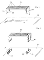
- a printed circuit board 30 is shown having contact pads 31, and an antenna 33.
- the antenna includes several transmitting and receiving antennas 34. It also includes legs 35.
- the different transmitting and receiving antennas 34 have parts 36 that extends along the legs 35 of the antenna to enable contact with the contact pads 31 on the printed circuit board 30.
- the extending parts 36 extend down over the end of the legs 35 and up on the other side of the legs 35. This construction enables better contact between the antenna 33 and the printed circuit board 30.
- the antenna 33 shown in fig. 3 is soldered onto the printed circuit board 30.
- FIG. 4 Another solution for attaching an antenna 33 to a printed circuit board 30 is shown in fig. 4, where the antenna 33 is attached to the printed circuit board 30 having an antenna connector 37 mounted, preferably by soldering, on the printed circuit board 30.
- the antenna connectors 37 includes contact members 38 mounted in slots (not shown) on the antenna connector 37, where each contact member 38 includes two contact parts 39 and 40.
- the first contact part 39 has mainly a contact function, while the second contact part 40 also has a holding function.
- the second contact part 40 will snap into a recession 41 on the antenna 33.
- the second contact part 40 will hold the antenna 33 firmly so that a good contact is established between the antenna 33 and the printed circuit board 30.
- the second contact parts 40 can easily be bent outwards from the antenna 33 thus releasing the antenna 33 from the antenna connector 37.
- FIG. 5 is yet another way of attaching an antenna 33 to a printed circuit board 30 shown, where antenna connectors 42 having a raised section 43 are mounted, preferably by soldering, onto the printed circuit board 30.
- the raised section 43 of the antenna connector 42 has a recession 44, which overlaps with a corresponding recession 46 on the antenna 33.
- the antenna connector 42 also includes contact members 45 mounted in slots (not shown) on the antenna connector 42, where the part of the contact members 45 having contact with the antenna 33 has a closed end or at least an end pointing downwards. Any metal parts in the antenna connector 42 will affect the antenna 33, but having a closed end or at least an end pointing downwards minimises the effect from the antenna connector 42 on the antenna 33.
- antenna connectors 42 having three and two contact members 45 respectively.
- the antenna connectors 42 are provided with numerous slots (not shown).
- the antenna connector 42 will be provided with a suitable number of contact members 45, while the rest of the slots will be empty.
- the embodiments shown in fig. 4 and 6 are provided with numerous slots to adapt to different types of antennas 33.
- the contact members 45 When an antenna 33 is placed in the antenna connector 42 the contact members 45 will be bend outwards from the raised section 43 until the recession 46 on the antenna 33 snaps into the recession 44 on the antenna connector 42.
- the contact between the contact members 45 and the antenna 33 is earlier shown described with reference to fig. 3.
- the antenna 33 is released by pressing the legs 47 inwards and thereby pushing the contact members 45 away, releasing the snapped recessions 44 and 46, and thereafter lifting the antenna 33.
- an antenna 33 having extra holding means 48 for increasing the attaching force between the antenna 33 and the printed circuit board 30.
- the extra holding means 48 includes snapping members that are inserted in recessions 49 on the printed circuit board 30, when mounting the antenna 33 onto the printed circuit board 30.
- FIG. 7 a schematic view of an antenna probe 50 for testing a radio part (not shown) on the print circuit board 30.
- the antenna probe 50 has some contact cables 52 for connecting to measuring equipment (not shown) and some coax cables 53 to attach to some grounding pins 51.
- the antenna probe 50 has in this example a similar structure to that of the earlier described antennas 33, but it could have any other design as long as the grounding pins 51 fits into the antenna connector 42 and that they are connected to some grounding pads 54.
- the antenna probe 50 lacks any recessions that corresponds to the recessions 44 of the antenna connector 42 (fig. 5) or that the second contact part 40 (shown in fig. 4), which snaps into the recessions and holds the antenna probe 50 firmly to the printed circuit board 30. This enables the antenna probe 50 to easily be placed in the antenna connector 37 or 42, and that tests can be conducted on the radio part.
- the antenna probe 50 and the antenna 33 can be held and placed in the antenna connector 42 by the same rotating tool (not shown). While the antenna probe 50 is placed onto the antenna connector 42 for conducting the tests the antenna 33 can be held in another position waiting to be placed onto the antenna connector 42 after the tests have been completed.
- the rotating tool lifts the antenna probe 50 and rotates so that the antenna 33 is placed in the mounting position and thereafter placed onto the antenna connector 42.
Landscapes
- Engineering & Computer Science (AREA)
- Computer Networks & Wireless Communication (AREA)
- Support Of Aerials (AREA)
- Telephone Set Structure (AREA)
- Coupling Device And Connection With Printed Circuit (AREA)
- Details Of Aerials (AREA)
Applications Claiming Priority (2)
| Application Number | Priority Date | Filing Date | Title |
|---|---|---|---|
| GB0006418A GB2360398A (en) | 2000-03-16 | 2000-03-16 | Antenna connector allowing releasable connection of an antenna to a PCB |
| GB0006418 | 2000-03-16 |
Publications (3)
| Publication Number | Publication Date |
|---|---|
| EP1137099A2 true EP1137099A2 (fr) | 2001-09-26 |
| EP1137099A3 EP1137099A3 (fr) | 2003-09-03 |
| EP1137099B1 EP1137099B1 (fr) | 2006-04-19 |
Family
ID=9887791
Family Applications (1)
| Application Number | Title | Priority Date | Filing Date |
|---|---|---|---|
| EP01301845A Expired - Lifetime EP1137099B1 (fr) | 2000-03-16 | 2001-02-28 | Connecteur d'antenne |
Country Status (5)
| Country | Link |
|---|---|
| US (1) | US6426724B2 (fr) |
| EP (1) | EP1137099B1 (fr) |
| AT (1) | ATE323951T1 (fr) |
| DE (1) | DE60118827T2 (fr) |
| GB (1) | GB2360398A (fr) |
Cited By (11)
| Publication number | Priority date | Publication date | Assignee | Title |
|---|---|---|---|---|
| GB2385992A (en) * | 2002-02-25 | 2003-09-03 | Nec Corp | Antenna installation structure |
| EP1351332A1 (fr) * | 2001-12-11 | 2003-10-08 | Ngk Insulators, Ltd. | Boítier de protection ou antenne plane sur un circuit imprimé |
| EP1488475A2 (fr) * | 2002-03-08 | 2004-12-22 | General Instrument Corporation | Antenne modulaire en circuit imprime |
| FR2868880A1 (fr) * | 2004-09-02 | 2005-10-14 | Siemens Vdo Automotive Sas | Antenne pour capteur de pression de pneumatique et capteur equipe d'une telle antenne |
| WO2006077430A1 (fr) * | 2005-01-20 | 2006-07-27 | Antenova Limited | Antenne et radio integrees a deux modules |
| NL1029804C2 (nl) * | 2005-08-25 | 2007-02-27 | Silverlink B V | Antenne-inrichting, antenne-basis en antenne-eenheid. |
| EP1826867A1 (fr) * | 2006-02-22 | 2007-08-29 | Alps Electric Co., Ltd. | Module d'antenne intégrée |
| EP1933416A1 (fr) * | 2006-12-13 | 2008-06-18 | Alps Electric Co., Ltd. | Module d'antenne intégrée |
| FR2962599A1 (fr) * | 2010-07-07 | 2012-01-13 | Valeo Securite Habitacle | Module d'antenne pour vehicule comprenant un circuit et un support d'antenne |
| EP2434575A1 (fr) * | 2010-09-28 | 2012-03-28 | Raytheon Company | Antenne enfichable |
| CN103700940A (zh) * | 2012-09-27 | 2014-04-02 | 阿尔卑斯电气株式会社 | 天线装置的制造方法 |
Families Citing this family (23)
| Publication number | Priority date | Publication date | Assignee | Title |
|---|---|---|---|---|
| JP2002151928A (ja) * | 2000-11-08 | 2002-05-24 | Toshiba Corp | アンテナ、及びアンテナを内蔵する電子機器 |
| GB0212043D0 (en) * | 2002-05-27 | 2002-07-03 | Sendo Int Ltd | Method of connecting an antenna to a pcb and connector there for |
| GB2398170A (en) * | 2003-02-04 | 2004-08-11 | Vladimir Stoiljkovic | Surface mount antenna with metal clips |
| US7750854B2 (en) * | 2003-02-10 | 2010-07-06 | Sony Ericsson Mobile Communications Ab | Combined speaker and antenna component |
| JP2004325239A (ja) * | 2003-04-24 | 2004-11-18 | Sharp Corp | アンテナゲイン特定装置および無線通信装置 |
| US7161544B2 (en) * | 2004-12-29 | 2007-01-09 | Sony Ericsson Mobile Communications | Mobile terminals including a built-in radio frequency test interface |
| US7379021B2 (en) * | 2005-11-01 | 2008-05-27 | Arcadyan Technology Corporation | Circuit board |
| JP4772602B2 (ja) * | 2006-06-29 | 2011-09-14 | 京セラ株式会社 | アンテナ装置および同アンテナ装置を搭載した携帯端末装置 |
| TWI345853B (en) * | 2006-08-08 | 2011-07-21 | Hon Hai Prec Ind Co Ltd | Movable antenna |
| CN101154759B (zh) * | 2006-09-30 | 2012-07-18 | 智易科技股份有限公司 | 天线基板与主基板的垂直结构 |
| DE102007000865B4 (de) | 2007-10-12 | 2011-06-30 | KOENIG & BAUER Aktiengesellschaft, 97080 | Druckeinheit mit mindestens zwei relativ zueinander in einer horizontalen Richtung abstandsveränderbaren Seitengestellteilen |
| DE102007000863A1 (de) | 2007-10-12 | 2009-04-23 | Koenig & Bauer Aktiengesellschaft | Druckeinheit mit mindestens zwei relativ zueinander in einer horizontalen Richtung abstandsveränderbaren Seitengestellteilen |
| TWM343929U (en) * | 2008-01-22 | 2008-11-01 | Wistron Neweb Corp | Flexible antenna module |
| KR101675375B1 (ko) * | 2009-11-23 | 2016-11-14 | 삼성전자 주식회사 | 휴대단말기 내장용 pcb 안테나 |
| GB2477290B (en) * | 2010-01-27 | 2014-04-09 | Harris Corp | A dielectrically loaded antenna and radio communication apparatus |
| US8599101B2 (en) | 2010-01-27 | 2013-12-03 | Sarantel Limited | Dielectrically loaded antenna and radio communication apparatus |
| WO2012149722A1 (fr) * | 2011-09-02 | 2012-11-08 | 华为技术有限公司 | Système à antenne active |
| US9867291B2 (en) * | 2011-11-30 | 2018-01-09 | Digi Internationl Inc. | Embedded coplanar interconnect |
| JP2014072563A (ja) * | 2012-09-27 | 2014-04-21 | Alps Electric Co Ltd | アンテナ装置 |
| TWI509876B (zh) * | 2012-10-08 | 2015-11-21 | Universal Scient Ind Co Ltd | Antenna module |
| US20140300527A1 (en) * | 2013-04-03 | 2014-10-09 | Ralink Technology Corp. | Antenna for Wireless Communication Device |
| US9912062B1 (en) * | 2013-06-27 | 2018-03-06 | Amazon Technologies, Inc. | Support for circuit traces |
| JP2018148448A (ja) * | 2017-03-07 | 2018-09-20 | 住友電装株式会社 | 無線受信機能付電気接続箱 |
Citations (6)
| Publication number | Priority date | Publication date | Assignee | Title |
|---|---|---|---|---|
| US5490788A (en) * | 1994-11-01 | 1996-02-13 | Emc Technology, Inc. | Surface mount terminal for electrical component |
| EP0867967A2 (fr) * | 1997-03-27 | 1998-09-30 | Nokia Mobile Phones Ltd. | Antenne pour dispositifs de communication sans fil |
| EP0902508A2 (fr) * | 1997-09-11 | 1999-03-17 | The Whitaker Corporation | Méthode de connexion d'une antenne-cadre à un circuit imprimé et son assemblage |
| EP0929115A1 (fr) * | 1998-01-09 | 1999-07-14 | Nokia Mobile Phones Ltd. | Antenne pour un appareil de communication mobile |
| DE29922053U1 (de) * | 1998-12-23 | 2000-02-17 | Nokia Mobile Phones Ltd | Funkgerät |
| EP1032075A2 (fr) * | 1999-02-26 | 2000-08-30 | Berg Electronics Manufacturing B.V. | Connecteur électrique pour antennes à boucles |
Family Cites Families (2)
| Publication number | Priority date | Publication date | Assignee | Title |
|---|---|---|---|---|
| CA2166996A1 (fr) * | 1993-07-29 | 1995-02-09 | Gary Yasamura | Connecteur d'interconnexion d'elements assimilables a des cartes de circuit imprime |
| TW367126U (en) * | 1998-03-20 | 1999-08-11 | Molex Taiwan Ltd | Antenna connector for communication supplies |
-
2000
- 2000-03-16 GB GB0006418A patent/GB2360398A/en active Pending
-
2001
- 2001-02-28 AT AT01301845T patent/ATE323951T1/de not_active IP Right Cessation
- 2001-02-28 EP EP01301845A patent/EP1137099B1/fr not_active Expired - Lifetime
- 2001-02-28 DE DE60118827T patent/DE60118827T2/de not_active Expired - Lifetime
- 2001-03-13 US US09/804,197 patent/US6426724B2/en not_active Expired - Fee Related
Patent Citations (6)
| Publication number | Priority date | Publication date | Assignee | Title |
|---|---|---|---|---|
| US5490788A (en) * | 1994-11-01 | 1996-02-13 | Emc Technology, Inc. | Surface mount terminal for electrical component |
| EP0867967A2 (fr) * | 1997-03-27 | 1998-09-30 | Nokia Mobile Phones Ltd. | Antenne pour dispositifs de communication sans fil |
| EP0902508A2 (fr) * | 1997-09-11 | 1999-03-17 | The Whitaker Corporation | Méthode de connexion d'une antenne-cadre à un circuit imprimé et son assemblage |
| EP0929115A1 (fr) * | 1998-01-09 | 1999-07-14 | Nokia Mobile Phones Ltd. | Antenne pour un appareil de communication mobile |
| DE29922053U1 (de) * | 1998-12-23 | 2000-02-17 | Nokia Mobile Phones Ltd | Funkgerät |
| EP1032075A2 (fr) * | 1999-02-26 | 2000-08-30 | Berg Electronics Manufacturing B.V. | Connecteur électrique pour antennes à boucles |
Cited By (17)
| Publication number | Priority date | Publication date | Assignee | Title |
|---|---|---|---|---|
| EP1351332A1 (fr) * | 2001-12-11 | 2003-10-08 | Ngk Insulators, Ltd. | Boítier de protection ou antenne plane sur un circuit imprimé |
| GB2385992A (en) * | 2002-02-25 | 2003-09-03 | Nec Corp | Antenna installation structure |
| GB2385992B (en) * | 2002-02-25 | 2004-04-07 | Nec Corp | Antenna installation structure and information terminal having an antenna |
| US6980156B2 (en) | 2002-02-25 | 2005-12-27 | Nec Corporation | Antenna installation structure and information terminal having an antenna |
| EP1488475A2 (fr) * | 2002-03-08 | 2004-12-22 | General Instrument Corporation | Antenne modulaire en circuit imprime |
| EP1488475A4 (fr) * | 2002-03-08 | 2005-09-21 | Gen Instrument Corp | Antenne modulaire en circuit imprime |
| FR2868880A1 (fr) * | 2004-09-02 | 2005-10-14 | Siemens Vdo Automotive Sas | Antenne pour capteur de pression de pneumatique et capteur equipe d'une telle antenne |
| WO2006077430A1 (fr) * | 2005-01-20 | 2006-07-27 | Antenova Limited | Antenne et radio integrees a deux modules |
| NL1029804C2 (nl) * | 2005-08-25 | 2007-02-27 | Silverlink B V | Antenne-inrichting, antenne-basis en antenne-eenheid. |
| EP1758202A1 (fr) * | 2005-08-25 | 2007-02-28 | Silverlink B.V. | Antenne, embase d'antenne et unité d'antenne |
| EP1826867A1 (fr) * | 2006-02-22 | 2007-08-29 | Alps Electric Co., Ltd. | Module d'antenne intégrée |
| EP1933416A1 (fr) * | 2006-12-13 | 2008-06-18 | Alps Electric Co., Ltd. | Module d'antenne intégrée |
| FR2962599A1 (fr) * | 2010-07-07 | 2012-01-13 | Valeo Securite Habitacle | Module d'antenne pour vehicule comprenant un circuit et un support d'antenne |
| EP2434575A1 (fr) * | 2010-09-28 | 2012-03-28 | Raytheon Company | Antenne enfichable |
| US8654031B2 (en) | 2010-09-28 | 2014-02-18 | Raytheon Company | Plug-in antenna |
| CN103700940A (zh) * | 2012-09-27 | 2014-04-02 | 阿尔卑斯电气株式会社 | 天线装置的制造方法 |
| CN103700940B (zh) * | 2012-09-27 | 2015-11-18 | 阿尔卑斯电气株式会社 | 天线装置的制造方法 |
Also Published As
| Publication number | Publication date |
|---|---|
| ATE323951T1 (de) | 2006-05-15 |
| US20010052879A1 (en) | 2001-12-20 |
| EP1137099A3 (fr) | 2003-09-03 |
| EP1137099B1 (fr) | 2006-04-19 |
| DE60118827D1 (de) | 2006-05-24 |
| GB0006418D0 (en) | 2000-05-03 |
| GB2360398A (en) | 2001-09-19 |
| US6426724B2 (en) | 2002-07-30 |
| DE60118827T2 (de) | 2006-11-30 |
Similar Documents
| Publication | Publication Date | Title |
|---|---|---|
| EP1137099B1 (fr) | Connecteur d'antenne | |
| CN101077025B (zh) | 具有来自显示器的减小干扰能量的移动无线通信设备及有关方法 | |
| EP0680155A1 (fr) | Module émetteur-récepteur et combiné | |
| KR20000034939A (ko) | 와치 타입 휴대용 무선단말기 | |
| US7130004B2 (en) | Display arrangement | |
| JP2970668B2 (ja) | プリント回路基板への部品の電気的接続構造及び方法 | |
| US6350133B2 (en) | Display holder | |
| CN111474750A (zh) | 一种显示模组及终端 | |
| CA2555744C (fr) | Essai de fixation destine a des dispositifs sans fil assembles | |
| US6504595B2 (en) | LCD connection | |
| KR100630127B1 (ko) | 보조 표시부를 구비한 폴더 타입 무선 단말기 및 보조표시부 구동방법 | |
| WO2009101468A1 (fr) | Connecteur électrique souple destiné à être monté sur une carte de circuit imprimé | |
| US20080042884A1 (en) | Keyboard with wireless electronic device | |
| KR100744363B1 (ko) | 휴대용 단말기의 인쇄회로기판 | |
| US20090257203A1 (en) | Mobile communication device with replaceable functional modules | |
| US20070004471A1 (en) | Electronic device including first and second parts and a flexible printed circuit board for electrically connecting the two | |
| CN110165451B (zh) | Btb连接器的固定装置及移动终端 | |
| JP2001077893A (ja) | 携帯端末アダプター | |
| KR200366236Y1 (ko) | 터치 스크린이 구비된 휴대폰 | |
| JP3165128B2 (ja) | 無線端末装置 | |
| KR20080067486A (ko) | 휴대용 단말기 | |
| CN112751956A (zh) | 一种办公用智能电话系统 | |
| KR200348924Y1 (ko) | 플립에설치된보조키입력장치 | |
| KR20040097651A (ko) | 이동통신단말기용 배터리팩 접속장치 | |
| KR200357180Y1 (ko) | 모뎀을 이용한 시리얼 데이터 자동송수신 휴대장치 |
Legal Events
| Date | Code | Title | Description |
|---|---|---|---|
| PUAI | Public reference made under article 153(3) epc to a published international application that has entered the european phase |
Free format text: ORIGINAL CODE: 0009012 |
|
| AK | Designated contracting states |
Kind code of ref document: A2 Designated state(s): AT BE CH CY DE DK ES FI FR GB GR IE IT LI LU MC NL PT SE TR |
|
| AX | Request for extension of the european patent |
Free format text: AL;LT;LV;MK;RO;SI |
|
| RAP1 | Party data changed (applicant data changed or rights of an application transferred) |
Owner name: NOKIA CORPORATION |
|
| PUAL | Search report despatched |
Free format text: ORIGINAL CODE: 0009013 |
|
| AK | Designated contracting states |
Kind code of ref document: A3 Designated state(s): AT BE CH CY DE DK ES FI FR GB GR IE IT LI LU MC NL PT SE TR |
|
| AX | Request for extension of the european patent |
Extension state: AL LT LV MK RO SI |
|
| 17P | Request for examination filed |
Effective date: 20040303 |
|
| AKX | Designation fees paid |
Designated state(s): AT BE CH CY DE DK ES FI FR GB GR IE IT LI LU MC NL PT SE TR |
|
| 17Q | First examination report despatched |
Effective date: 20040906 |
|
| GRAP | Despatch of communication of intention to grant a patent |
Free format text: ORIGINAL CODE: EPIDOSNIGR1 |
|
| GRAS | Grant fee paid |
Free format text: ORIGINAL CODE: EPIDOSNIGR3 |
|
| GRAA | (expected) grant |
Free format text: ORIGINAL CODE: 0009210 |
|
| AK | Designated contracting states |
Kind code of ref document: B1 Designated state(s): AT BE CH CY DE DK ES FI FR GB GR IE IT LI LU MC NL PT SE TR |
|
| PG25 | Lapsed in a contracting state [announced via postgrant information from national office to epo] |
Ref country code: IT Free format text: LAPSE BECAUSE OF FAILURE TO SUBMIT A TRANSLATION OF THE DESCRIPTION OR TO PAY THE FEE WITHIN THE PRESCRIBED TIME-LIMIT;WARNING: LAPSES OF ITALIAN PATENTS WITH EFFECTIVE DATE BEFORE 2007 MAY HAVE OCCURRED AT ANY TIME BEFORE 2007. THE CORRECT EFFECTIVE DATE MAY BE DIFFERENT FROM THE ONE RECORDED. Effective date: 20060419 Ref country code: FI Free format text: LAPSE BECAUSE OF FAILURE TO SUBMIT A TRANSLATION OF THE DESCRIPTION OR TO PAY THE FEE WITHIN THE PRESCRIBED TIME-LIMIT Effective date: 20060419 Ref country code: AT Free format text: LAPSE BECAUSE OF FAILURE TO SUBMIT A TRANSLATION OF THE DESCRIPTION OR TO PAY THE FEE WITHIN THE PRESCRIBED TIME-LIMIT Effective date: 20060419 Ref country code: BE Free format text: LAPSE BECAUSE OF FAILURE TO SUBMIT A TRANSLATION OF THE DESCRIPTION OR TO PAY THE FEE WITHIN THE PRESCRIBED TIME-LIMIT Effective date: 20060419 Ref country code: LI Free format text: LAPSE BECAUSE OF FAILURE TO SUBMIT A TRANSLATION OF THE DESCRIPTION OR TO PAY THE FEE WITHIN THE PRESCRIBED TIME-LIMIT Effective date: 20060419 Ref country code: CH Free format text: LAPSE BECAUSE OF FAILURE TO SUBMIT A TRANSLATION OF THE DESCRIPTION OR TO PAY THE FEE WITHIN THE PRESCRIBED TIME-LIMIT Effective date: 20060419 |
|
| REG | Reference to a national code |
Ref country code: GB Ref legal event code: FG4D |
|
| REF | Corresponds to: |
Ref document number: 60118827 Country of ref document: DE Date of ref document: 20060524 Kind code of ref document: P |
|
| REG | Reference to a national code |
Ref country code: IE Ref legal event code: FG4D |
|
| PG25 | Lapsed in a contracting state [announced via postgrant information from national office to epo] |
Ref country code: DK Free format text: LAPSE BECAUSE OF FAILURE TO SUBMIT A TRANSLATION OF THE DESCRIPTION OR TO PAY THE FEE WITHIN THE PRESCRIBED TIME-LIMIT Effective date: 20060719 Ref country code: SE Free format text: LAPSE BECAUSE OF FAILURE TO SUBMIT A TRANSLATION OF THE DESCRIPTION OR TO PAY THE FEE WITHIN THE PRESCRIBED TIME-LIMIT Effective date: 20060719 |
|
| PG25 | Lapsed in a contracting state [announced via postgrant information from national office to epo] |
Ref country code: ES Free format text: LAPSE BECAUSE OF FAILURE TO SUBMIT A TRANSLATION OF THE DESCRIPTION OR TO PAY THE FEE WITHIN THE PRESCRIBED TIME-LIMIT Effective date: 20060730 |
|
| PG25 | Lapsed in a contracting state [announced via postgrant information from national office to epo] |
Ref country code: PT Free format text: LAPSE BECAUSE OF FAILURE TO SUBMIT A TRANSLATION OF THE DESCRIPTION OR TO PAY THE FEE WITHIN THE PRESCRIBED TIME-LIMIT Effective date: 20060919 |
|
| ET | Fr: translation filed | ||
| REG | Reference to a national code |
Ref country code: CH Ref legal event code: PL |
|
| PLBE | No opposition filed within time limit |
Free format text: ORIGINAL CODE: 0009261 |
|
| STAA | Information on the status of an ep patent application or granted ep patent |
Free format text: STATUS: NO OPPOSITION FILED WITHIN TIME LIMIT |
|
| PG25 | Lapsed in a contracting state [announced via postgrant information from national office to epo] |
Ref country code: MC Free format text: LAPSE BECAUSE OF NON-PAYMENT OF DUE FEES Effective date: 20070228 |
|
| 26N | No opposition filed |
Effective date: 20070122 |
|
| PG25 | Lapsed in a contracting state [announced via postgrant information from national office to epo] |
Ref country code: IE Free format text: LAPSE BECAUSE OF NON-PAYMENT OF DUE FEES Effective date: 20070228 |
|
| PG25 | Lapsed in a contracting state [announced via postgrant information from national office to epo] |
Ref country code: GR Free format text: LAPSE BECAUSE OF FAILURE TO SUBMIT A TRANSLATION OF THE DESCRIPTION OR TO PAY THE FEE WITHIN THE PRESCRIBED TIME-LIMIT Effective date: 20060720 |
|
| PG25 | Lapsed in a contracting state [announced via postgrant information from national office to epo] |
Ref country code: LU Free format text: LAPSE BECAUSE OF NON-PAYMENT OF DUE FEES Effective date: 20070228 Ref country code: CY Free format text: LAPSE BECAUSE OF FAILURE TO SUBMIT A TRANSLATION OF THE DESCRIPTION OR TO PAY THE FEE WITHIN THE PRESCRIBED TIME-LIMIT Effective date: 20060419 |
|
| PG25 | Lapsed in a contracting state [announced via postgrant information from national office to epo] |
Ref country code: TR Free format text: LAPSE BECAUSE OF FAILURE TO SUBMIT A TRANSLATION OF THE DESCRIPTION OR TO PAY THE FEE WITHIN THE PRESCRIBED TIME-LIMIT Effective date: 20060419 |
|
| PGFP | Annual fee paid to national office [announced via postgrant information from national office to epo] |
Ref country code: FR Payment date: 20100223 Year of fee payment: 10 |
|
| PGFP | Annual fee paid to national office [announced via postgrant information from national office to epo] |
Ref country code: DE Payment date: 20100312 Year of fee payment: 10 Ref country code: GB Payment date: 20100224 Year of fee payment: 10 |
|
| PGFP | Annual fee paid to national office [announced via postgrant information from national office to epo] |
Ref country code: NL Payment date: 20100209 Year of fee payment: 10 |
|
| REG | Reference to a national code |
Ref country code: NL Ref legal event code: V1 Effective date: 20110901 |
|
| GBPC | Gb: european patent ceased through non-payment of renewal fee |
Effective date: 20110228 |
|
| REG | Reference to a national code |
Ref country code: FR Ref legal event code: ST Effective date: 20111102 |
|
| PG25 | Lapsed in a contracting state [announced via postgrant information from national office to epo] |
Ref country code: NL Free format text: LAPSE BECAUSE OF NON-PAYMENT OF DUE FEES Effective date: 20110901 |
|
| REG | Reference to a national code |
Ref country code: DE Ref legal event code: R119 Ref document number: 60118827 Country of ref document: DE Effective date: 20110901 |
|
| PG25 | Lapsed in a contracting state [announced via postgrant information from national office to epo] |
Ref country code: FR Free format text: LAPSE BECAUSE OF NON-PAYMENT OF DUE FEES Effective date: 20110228 |
|
| PG25 | Lapsed in a contracting state [announced via postgrant information from national office to epo] |
Ref country code: GB Free format text: LAPSE BECAUSE OF NON-PAYMENT OF DUE FEES Effective date: 20110228 |
|
| PG25 | Lapsed in a contracting state [announced via postgrant information from national office to epo] |
Ref country code: DE Free format text: LAPSE BECAUSE OF NON-PAYMENT OF DUE FEES Effective date: 20110901 |