EP1130740B1 - Elektrisches Hybridfahrzeug mit einer dynamoelektrischen Permanentmagnetmaschine - Google Patents
Elektrisches Hybridfahrzeug mit einer dynamoelektrischen Permanentmagnetmaschine Download PDFInfo
- Publication number
- EP1130740B1 EP1130740B1 EP00118187A EP00118187A EP1130740B1 EP 1130740 B1 EP1130740 B1 EP 1130740B1 EP 00118187 A EP00118187 A EP 00118187A EP 00118187 A EP00118187 A EP 00118187A EP 1130740 B1 EP1130740 B1 EP 1130740B1
- Authority
- EP
- European Patent Office
- Prior art keywords
- permanent magnet
- electric machine
- dynamo
- electric vehicle
- torque
- Prior art date
- Legal status (The legal status is an assumption and is not a legal conclusion. Google has not performed a legal analysis and makes no representation as to the accuracy of the status listed.)
- Expired - Lifetime
Links
Images


Classifications
-
- H—ELECTRICITY
- H02—GENERATION; CONVERSION OR DISTRIBUTION OF ELECTRIC POWER
- H02K—DYNAMO-ELECTRIC MACHINES
- H02K1/00—Details of the magnetic circuit
- H02K1/06—Details of the magnetic circuit characterised by the shape, form or construction
- H02K1/22—Rotating parts of the magnetic circuit
- H02K1/27—Rotor cores with permanent magnets
-
- B—PERFORMING OPERATIONS; TRANSPORTING
- B60—VEHICLES IN GENERAL
- B60K—ARRANGEMENT OR MOUNTING OF PROPULSION UNITS OR OF TRANSMISSIONS IN VEHICLES; ARRANGEMENT OR MOUNTING OF PLURAL DIVERSE PRIME-MOVERS IN VEHICLES; AUXILIARY DRIVES FOR VEHICLES; INSTRUMENTATION OR DASHBOARDS FOR VEHICLES; ARRANGEMENTS IN CONNECTION WITH COOLING, AIR INTAKE, GAS EXHAUST OR FUEL SUPPLY OF PROPULSION UNITS IN VEHICLES
- B60K6/00—Arrangement or mounting of plural diverse prime-movers for mutual or common propulsion, e.g. hybrid propulsion systems comprising electric motors and internal combustion engines ; Control systems therefor, i.e. systems controlling two or more prime movers, or controlling one of these prime movers and any of the transmission, drive or drive units Informative references: mechanical gearings with secondary electric drive F16H3/72; arrangements for handling mechanical energy structurally associated with the dynamo-electric machine H02K7/00; machines comprising structurally interrelated motor and generator parts H02K51/00; dynamo-electric machines not otherwise provided for in H02K see H02K99/00
- B60K6/20—Arrangement or mounting of plural diverse prime-movers for mutual or common propulsion, e.g. hybrid propulsion systems comprising electric motors and internal combustion engines ; Control systems therefor, i.e. systems controlling two or more prime movers, or controlling one of these prime movers and any of the transmission, drive or drive units Informative references: mechanical gearings with secondary electric drive F16H3/72; arrangements for handling mechanical energy structurally associated with the dynamo-electric machine H02K7/00; machines comprising structurally interrelated motor and generator parts H02K51/00; dynamo-electric machines not otherwise provided for in H02K see H02K99/00 the prime-movers consisting of electric motors and internal combustion engines, e.g. HEVs
- B60K6/22—Arrangement or mounting of plural diverse prime-movers for mutual or common propulsion, e.g. hybrid propulsion systems comprising electric motors and internal combustion engines ; Control systems therefor, i.e. systems controlling two or more prime movers, or controlling one of these prime movers and any of the transmission, drive or drive units Informative references: mechanical gearings with secondary electric drive F16H3/72; arrangements for handling mechanical energy structurally associated with the dynamo-electric machine H02K7/00; machines comprising structurally interrelated motor and generator parts H02K51/00; dynamo-electric machines not otherwise provided for in H02K see H02K99/00 the prime-movers consisting of electric motors and internal combustion engines, e.g. HEVs characterised by apparatus, components or means specially adapted for HEVs
- B60K6/26—Arrangement or mounting of plural diverse prime-movers for mutual or common propulsion, e.g. hybrid propulsion systems comprising electric motors and internal combustion engines ; Control systems therefor, i.e. systems controlling two or more prime movers, or controlling one of these prime movers and any of the transmission, drive or drive units Informative references: mechanical gearings with secondary electric drive F16H3/72; arrangements for handling mechanical energy structurally associated with the dynamo-electric machine H02K7/00; machines comprising structurally interrelated motor and generator parts H02K51/00; dynamo-electric machines not otherwise provided for in H02K see H02K99/00 the prime-movers consisting of electric motors and internal combustion engines, e.g. HEVs characterised by apparatus, components or means specially adapted for HEVs characterised by the motors or the generators
-
- B—PERFORMING OPERATIONS; TRANSPORTING
- B60—VEHICLES IN GENERAL
- B60K—ARRANGEMENT OR MOUNTING OF PROPULSION UNITS OR OF TRANSMISSIONS IN VEHICLES; ARRANGEMENT OR MOUNTING OF PLURAL DIVERSE PRIME-MOVERS IN VEHICLES; AUXILIARY DRIVES FOR VEHICLES; INSTRUMENTATION OR DASHBOARDS FOR VEHICLES; ARRANGEMENTS IN CONNECTION WITH COOLING, AIR INTAKE, GAS EXHAUST OR FUEL SUPPLY OF PROPULSION UNITS IN VEHICLES
- B60K6/00—Arrangement or mounting of plural diverse prime-movers for mutual or common propulsion, e.g. hybrid propulsion systems comprising electric motors and internal combustion engines ; Control systems therefor, i.e. systems controlling two or more prime movers, or controlling one of these prime movers and any of the transmission, drive or drive units Informative references: mechanical gearings with secondary electric drive F16H3/72; arrangements for handling mechanical energy structurally associated with the dynamo-electric machine H02K7/00; machines comprising structurally interrelated motor and generator parts H02K51/00; dynamo-electric machines not otherwise provided for in H02K see H02K99/00
- B60K6/20—Arrangement or mounting of plural diverse prime-movers for mutual or common propulsion, e.g. hybrid propulsion systems comprising electric motors and internal combustion engines ; Control systems therefor, i.e. systems controlling two or more prime movers, or controlling one of these prime movers and any of the transmission, drive or drive units Informative references: mechanical gearings with secondary electric drive F16H3/72; arrangements for handling mechanical energy structurally associated with the dynamo-electric machine H02K7/00; machines comprising structurally interrelated motor and generator parts H02K51/00; dynamo-electric machines not otherwise provided for in H02K see H02K99/00 the prime-movers consisting of electric motors and internal combustion engines, e.g. HEVs
- B60K6/42—Arrangement or mounting of plural diverse prime-movers for mutual or common propulsion, e.g. hybrid propulsion systems comprising electric motors and internal combustion engines ; Control systems therefor, i.e. systems controlling two or more prime movers, or controlling one of these prime movers and any of the transmission, drive or drive units Informative references: mechanical gearings with secondary electric drive F16H3/72; arrangements for handling mechanical energy structurally associated with the dynamo-electric machine H02K7/00; machines comprising structurally interrelated motor and generator parts H02K51/00; dynamo-electric machines not otherwise provided for in H02K see H02K99/00 the prime-movers consisting of electric motors and internal combustion engines, e.g. HEVs characterised by the architecture of the hybrid electric vehicle
- B60K6/44—Series-parallel type
- B60K6/442—Series-parallel switching type
-
- B—PERFORMING OPERATIONS; TRANSPORTING
- B60—VEHICLES IN GENERAL
- B60K—ARRANGEMENT OR MOUNTING OF PROPULSION UNITS OR OF TRANSMISSIONS IN VEHICLES; ARRANGEMENT OR MOUNTING OF PLURAL DIVERSE PRIME-MOVERS IN VEHICLES; AUXILIARY DRIVES FOR VEHICLES; INSTRUMENTATION OR DASHBOARDS FOR VEHICLES; ARRANGEMENTS IN CONNECTION WITH COOLING, AIR INTAKE, GAS EXHAUST OR FUEL SUPPLY OF PROPULSION UNITS IN VEHICLES
- B60K6/00—Arrangement or mounting of plural diverse prime-movers for mutual or common propulsion, e.g. hybrid propulsion systems comprising electric motors and internal combustion engines ; Control systems therefor, i.e. systems controlling two or more prime movers, or controlling one of these prime movers and any of the transmission, drive or drive units Informative references: mechanical gearings with secondary electric drive F16H3/72; arrangements for handling mechanical energy structurally associated with the dynamo-electric machine H02K7/00; machines comprising structurally interrelated motor and generator parts H02K51/00; dynamo-electric machines not otherwise provided for in H02K see H02K99/00
- B60K6/20—Arrangement or mounting of plural diverse prime-movers for mutual or common propulsion, e.g. hybrid propulsion systems comprising electric motors and internal combustion engines ; Control systems therefor, i.e. systems controlling two or more prime movers, or controlling one of these prime movers and any of the transmission, drive or drive units Informative references: mechanical gearings with secondary electric drive F16H3/72; arrangements for handling mechanical energy structurally associated with the dynamo-electric machine H02K7/00; machines comprising structurally interrelated motor and generator parts H02K51/00; dynamo-electric machines not otherwise provided for in H02K see H02K99/00 the prime-movers consisting of electric motors and internal combustion engines, e.g. HEVs
- B60K6/42—Arrangement or mounting of plural diverse prime-movers for mutual or common propulsion, e.g. hybrid propulsion systems comprising electric motors and internal combustion engines ; Control systems therefor, i.e. systems controlling two or more prime movers, or controlling one of these prime movers and any of the transmission, drive or drive units Informative references: mechanical gearings with secondary electric drive F16H3/72; arrangements for handling mechanical energy structurally associated with the dynamo-electric machine H02K7/00; machines comprising structurally interrelated motor and generator parts H02K51/00; dynamo-electric machines not otherwise provided for in H02K see H02K99/00 the prime-movers consisting of electric motors and internal combustion engines, e.g. HEVs characterised by the architecture of the hybrid electric vehicle
- B60K6/48—Parallel type
-
- B—PERFORMING OPERATIONS; TRANSPORTING
- B60—VEHICLES IN GENERAL
- B60L—PROPULSION OF ELECTRICALLY-PROPELLED VEHICLES; SUPPLYING ELECTRIC POWER FOR AUXILIARY EQUIPMENT OF ELECTRICALLY-PROPELLED VEHICLES; ELECTRODYNAMIC BRAKE SYSTEMS FOR VEHICLES IN GENERAL; MAGNETIC SUSPENSION OR LEVITATION FOR VEHICLES; MONITORING OPERATING VARIABLES OF ELECTRICALLY-PROPELLED VEHICLES; ELECTRIC SAFETY DEVICES FOR ELECTRICALLY-PROPELLED VEHICLES
- B60L15/00—Methods, circuits, or devices for controlling the traction-motor speed of electrically-propelled vehicles
- B60L15/20—Methods, circuits, or devices for controlling the traction-motor speed of electrically-propelled vehicles for control of the vehicle or its driving motor to achieve a desired performance, e.g. speed, torque, programmed variation of speed
- B60L15/2009—Methods, circuits, or devices for controlling the traction-motor speed of electrically-propelled vehicles for control of the vehicle or its driving motor to achieve a desired performance, e.g. speed, torque, programmed variation of speed for braking
-
- B—PERFORMING OPERATIONS; TRANSPORTING
- B60—VEHICLES IN GENERAL
- B60L—PROPULSION OF ELECTRICALLY-PROPELLED VEHICLES; SUPPLYING ELECTRIC POWER FOR AUXILIARY EQUIPMENT OF ELECTRICALLY-PROPELLED VEHICLES; ELECTRODYNAMIC BRAKE SYSTEMS FOR VEHICLES IN GENERAL; MAGNETIC SUSPENSION OR LEVITATION FOR VEHICLES; MONITORING OPERATING VARIABLES OF ELECTRICALLY-PROPELLED VEHICLES; ELECTRIC SAFETY DEVICES FOR ELECTRICALLY-PROPELLED VEHICLES
- B60L50/00—Electric propulsion with power supplied within the vehicle
- B60L50/10—Electric propulsion with power supplied within the vehicle using propulsion power supplied by engine-driven generators, e.g. generators driven by combustion engines
- B60L50/16—Electric propulsion with power supplied within the vehicle using propulsion power supplied by engine-driven generators, e.g. generators driven by combustion engines with provision for separate direct mechanical propulsion
-
- B—PERFORMING OPERATIONS; TRANSPORTING
- B60—VEHICLES IN GENERAL
- B60L—PROPULSION OF ELECTRICALLY-PROPELLED VEHICLES; SUPPLYING ELECTRIC POWER FOR AUXILIARY EQUIPMENT OF ELECTRICALLY-PROPELLED VEHICLES; ELECTRODYNAMIC BRAKE SYSTEMS FOR VEHICLES IN GENERAL; MAGNETIC SUSPENSION OR LEVITATION FOR VEHICLES; MONITORING OPERATING VARIABLES OF ELECTRICALLY-PROPELLED VEHICLES; ELECTRIC SAFETY DEVICES FOR ELECTRICALLY-PROPELLED VEHICLES
- B60L50/00—Electric propulsion with power supplied within the vehicle
- B60L50/50—Electric propulsion with power supplied within the vehicle using propulsion power supplied by batteries or fuel cells
- B60L50/60—Electric propulsion with power supplied within the vehicle using propulsion power supplied by batteries or fuel cells using power supplied by batteries
- B60L50/61—Electric propulsion with power supplied within the vehicle using propulsion power supplied by batteries or fuel cells using power supplied by batteries by batteries charged by engine-driven generators, e.g. series hybrid electric vehicles
-
- B—PERFORMING OPERATIONS; TRANSPORTING
- B60—VEHICLES IN GENERAL
- B60L—PROPULSION OF ELECTRICALLY-PROPELLED VEHICLES; SUPPLYING ELECTRIC POWER FOR AUXILIARY EQUIPMENT OF ELECTRICALLY-PROPELLED VEHICLES; ELECTRODYNAMIC BRAKE SYSTEMS FOR VEHICLES IN GENERAL; MAGNETIC SUSPENSION OR LEVITATION FOR VEHICLES; MONITORING OPERATING VARIABLES OF ELECTRICALLY-PROPELLED VEHICLES; ELECTRIC SAFETY DEVICES FOR ELECTRICALLY-PROPELLED VEHICLES
- B60L7/00—Electrodynamic brake systems for vehicles in general
- B60L7/02—Dynamic electric resistor braking
- B60L7/06—Dynamic electric resistor braking for vehicles propelled by ac motors
-
- B—PERFORMING OPERATIONS; TRANSPORTING
- B60—VEHICLES IN GENERAL
- B60W—CONJOINT CONTROL OF VEHICLE SUB-UNITS OF DIFFERENT TYPE OR DIFFERENT FUNCTION; CONTROL SYSTEMS SPECIALLY ADAPTED FOR HYBRID VEHICLES; ROAD VEHICLE DRIVE CONTROL SYSTEMS FOR PURPOSES NOT RELATED TO THE CONTROL OF A PARTICULAR SUB-UNIT
- B60W10/00—Conjoint control of vehicle sub-units of different type or different function
- B60W10/04—Conjoint control of vehicle sub-units of different type or different function including control of propulsion units
- B60W10/08—Conjoint control of vehicle sub-units of different type or different function including control of propulsion units including control of electric propulsion units, e.g. motors or generators
-
- H—ELECTRICITY
- H02—GENERATION; CONVERSION OR DISTRIBUTION OF ELECTRIC POWER
- H02K—DYNAMO-ELECTRIC MACHINES
- H02K1/00—Details of the magnetic circuit
- H02K1/06—Details of the magnetic circuit characterised by the shape, form or construction
- H02K1/22—Rotating parts of the magnetic circuit
- H02K1/27—Rotor cores with permanent magnets
- H02K1/2706—Inner rotors
- H02K1/272—Inner rotors the magnetisation axis of the magnets being perpendicular to the rotor axis
- H02K1/274—Inner rotors the magnetisation axis of the magnets being perpendicular to the rotor axis the rotor consisting of two or more circumferentially positioned magnets
- H02K1/2753—Inner rotors the magnetisation axis of the magnets being perpendicular to the rotor axis the rotor consisting of two or more circumferentially positioned magnets the rotor consisting of magnets or groups of magnets arranged with alternating polarity
- H02K1/276—Magnets embedded in the magnetic core, e.g. interior permanent magnets [IPM]
-
- H—ELECTRICITY
- H02—GENERATION; CONVERSION OR DISTRIBUTION OF ELECTRIC POWER
- H02K—DYNAMO-ELECTRIC MACHINES
- H02K21/00—Synchronous motors having permanent magnets; Synchronous generators having permanent magnets
- H02K21/02—Details
-
- H—ELECTRICITY
- H02—GENERATION; CONVERSION OR DISTRIBUTION OF ELECTRIC POWER
- H02K—DYNAMO-ELECTRIC MACHINES
- H02K21/00—Synchronous motors having permanent magnets; Synchronous generators having permanent magnets
- H02K21/12—Synchronous motors having permanent magnets; Synchronous generators having permanent magnets with stationary armatures and rotating magnets
- H02K21/14—Synchronous motors having permanent magnets; Synchronous generators having permanent magnets with stationary armatures and rotating magnets with magnets rotating within the armatures
-
- B—PERFORMING OPERATIONS; TRANSPORTING
- B60—VEHICLES IN GENERAL
- B60L—PROPULSION OF ELECTRICALLY-PROPELLED VEHICLES; SUPPLYING ELECTRIC POWER FOR AUXILIARY EQUIPMENT OF ELECTRICALLY-PROPELLED VEHICLES; ELECTRODYNAMIC BRAKE SYSTEMS FOR VEHICLES IN GENERAL; MAGNETIC SUSPENSION OR LEVITATION FOR VEHICLES; MONITORING OPERATING VARIABLES OF ELECTRICALLY-PROPELLED VEHICLES; ELECTRIC SAFETY DEVICES FOR ELECTRICALLY-PROPELLED VEHICLES
- B60L2210/00—Converter types
- B60L2210/40—DC to AC converters
-
- B—PERFORMING OPERATIONS; TRANSPORTING
- B60—VEHICLES IN GENERAL
- B60L—PROPULSION OF ELECTRICALLY-PROPELLED VEHICLES; SUPPLYING ELECTRIC POWER FOR AUXILIARY EQUIPMENT OF ELECTRICALLY-PROPELLED VEHICLES; ELECTRODYNAMIC BRAKE SYSTEMS FOR VEHICLES IN GENERAL; MAGNETIC SUSPENSION OR LEVITATION FOR VEHICLES; MONITORING OPERATING VARIABLES OF ELECTRICALLY-PROPELLED VEHICLES; ELECTRIC SAFETY DEVICES FOR ELECTRICALLY-PROPELLED VEHICLES
- B60L2240/00—Control parameters of input or output; Target parameters
- B60L2240/10—Vehicle control parameters
- B60L2240/12—Speed
-
- B—PERFORMING OPERATIONS; TRANSPORTING
- B60—VEHICLES IN GENERAL
- B60L—PROPULSION OF ELECTRICALLY-PROPELLED VEHICLES; SUPPLYING ELECTRIC POWER FOR AUXILIARY EQUIPMENT OF ELECTRICALLY-PROPELLED VEHICLES; ELECTRODYNAMIC BRAKE SYSTEMS FOR VEHICLES IN GENERAL; MAGNETIC SUSPENSION OR LEVITATION FOR VEHICLES; MONITORING OPERATING VARIABLES OF ELECTRICALLY-PROPELLED VEHICLES; ELECTRIC SAFETY DEVICES FOR ELECTRICALLY-PROPELLED VEHICLES
- B60L2240/00—Control parameters of input or output; Target parameters
- B60L2240/40—Drive Train control parameters
- B60L2240/42—Drive Train control parameters related to electric machines
- B60L2240/421—Speed
-
- B—PERFORMING OPERATIONS; TRANSPORTING
- B60—VEHICLES IN GENERAL
- B60L—PROPULSION OF ELECTRICALLY-PROPELLED VEHICLES; SUPPLYING ELECTRIC POWER FOR AUXILIARY EQUIPMENT OF ELECTRICALLY-PROPELLED VEHICLES; ELECTRODYNAMIC BRAKE SYSTEMS FOR VEHICLES IN GENERAL; MAGNETIC SUSPENSION OR LEVITATION FOR VEHICLES; MONITORING OPERATING VARIABLES OF ELECTRICALLY-PROPELLED VEHICLES; ELECTRIC SAFETY DEVICES FOR ELECTRICALLY-PROPELLED VEHICLES
- B60L2240/00—Control parameters of input or output; Target parameters
- B60L2240/40—Drive Train control parameters
- B60L2240/42—Drive Train control parameters related to electric machines
- B60L2240/423—Torque
-
- B—PERFORMING OPERATIONS; TRANSPORTING
- B60—VEHICLES IN GENERAL
- B60L—PROPULSION OF ELECTRICALLY-PROPELLED VEHICLES; SUPPLYING ELECTRIC POWER FOR AUXILIARY EQUIPMENT OF ELECTRICALLY-PROPELLED VEHICLES; ELECTRODYNAMIC BRAKE SYSTEMS FOR VEHICLES IN GENERAL; MAGNETIC SUSPENSION OR LEVITATION FOR VEHICLES; MONITORING OPERATING VARIABLES OF ELECTRICALLY-PROPELLED VEHICLES; ELECTRIC SAFETY DEVICES FOR ELECTRICALLY-PROPELLED VEHICLES
- B60L2240/00—Control parameters of input or output; Target parameters
- B60L2240/40—Drive Train control parameters
- B60L2240/44—Drive Train control parameters related to combustion engines
- B60L2240/441—Speed
-
- B—PERFORMING OPERATIONS; TRANSPORTING
- B60—VEHICLES IN GENERAL
- B60L—PROPULSION OF ELECTRICALLY-PROPELLED VEHICLES; SUPPLYING ELECTRIC POWER FOR AUXILIARY EQUIPMENT OF ELECTRICALLY-PROPELLED VEHICLES; ELECTRODYNAMIC BRAKE SYSTEMS FOR VEHICLES IN GENERAL; MAGNETIC SUSPENSION OR LEVITATION FOR VEHICLES; MONITORING OPERATING VARIABLES OF ELECTRICALLY-PROPELLED VEHICLES; ELECTRIC SAFETY DEVICES FOR ELECTRICALLY-PROPELLED VEHICLES
- B60L2240/00—Control parameters of input or output; Target parameters
- B60L2240/40—Drive Train control parameters
- B60L2240/44—Drive Train control parameters related to combustion engines
- B60L2240/443—Torque
-
- B—PERFORMING OPERATIONS; TRANSPORTING
- B60—VEHICLES IN GENERAL
- B60W—CONJOINT CONTROL OF VEHICLE SUB-UNITS OF DIFFERENT TYPE OR DIFFERENT FUNCTION; CONTROL SYSTEMS SPECIALLY ADAPTED FOR HYBRID VEHICLES; ROAD VEHICLE DRIVE CONTROL SYSTEMS FOR PURPOSES NOT RELATED TO THE CONTROL OF A PARTICULAR SUB-UNIT
- B60W30/00—Purposes of road vehicle drive control systems not related to the control of a particular sub-unit, e.g. of systems using conjoint control of vehicle sub-units, or advanced driver assistance systems for ensuring comfort, stability and safety or drive control systems for propelling or retarding the vehicle
- B60W30/18—Propelling the vehicle
- B60W30/18009—Propelling the vehicle related to particular drive situations
- B60W30/18036—Reversing
-
- Y—GENERAL TAGGING OF NEW TECHNOLOGICAL DEVELOPMENTS; GENERAL TAGGING OF CROSS-SECTIONAL TECHNOLOGIES SPANNING OVER SEVERAL SECTIONS OF THE IPC; TECHNICAL SUBJECTS COVERED BY FORMER USPC CROSS-REFERENCE ART COLLECTIONS [XRACs] AND DIGESTS
- Y02—TECHNOLOGIES OR APPLICATIONS FOR MITIGATION OR ADAPTATION AGAINST CLIMATE CHANGE
- Y02T—CLIMATE CHANGE MITIGATION TECHNOLOGIES RELATED TO TRANSPORTATION
- Y02T10/00—Road transport of goods or passengers
- Y02T10/60—Other road transportation technologies with climate change mitigation effect
- Y02T10/62—Hybrid vehicles
-
- Y—GENERAL TAGGING OF NEW TECHNOLOGICAL DEVELOPMENTS; GENERAL TAGGING OF CROSS-SECTIONAL TECHNOLOGIES SPANNING OVER SEVERAL SECTIONS OF THE IPC; TECHNICAL SUBJECTS COVERED BY FORMER USPC CROSS-REFERENCE ART COLLECTIONS [XRACs] AND DIGESTS
- Y02—TECHNOLOGIES OR APPLICATIONS FOR MITIGATION OR ADAPTATION AGAINST CLIMATE CHANGE
- Y02T—CLIMATE CHANGE MITIGATION TECHNOLOGIES RELATED TO TRANSPORTATION
- Y02T10/00—Road transport of goods or passengers
- Y02T10/60—Other road transportation technologies with climate change mitigation effect
- Y02T10/64—Electric machine technologies in electromobility
-
- Y—GENERAL TAGGING OF NEW TECHNOLOGICAL DEVELOPMENTS; GENERAL TAGGING OF CROSS-SECTIONAL TECHNOLOGIES SPANNING OVER SEVERAL SECTIONS OF THE IPC; TECHNICAL SUBJECTS COVERED BY FORMER USPC CROSS-REFERENCE ART COLLECTIONS [XRACs] AND DIGESTS
- Y02—TECHNOLOGIES OR APPLICATIONS FOR MITIGATION OR ADAPTATION AGAINST CLIMATE CHANGE
- Y02T—CLIMATE CHANGE MITIGATION TECHNOLOGIES RELATED TO TRANSPORTATION
- Y02T10/00—Road transport of goods or passengers
- Y02T10/60—Other road transportation technologies with climate change mitigation effect
- Y02T10/70—Energy storage systems for electromobility, e.g. batteries
-
- Y—GENERAL TAGGING OF NEW TECHNOLOGICAL DEVELOPMENTS; GENERAL TAGGING OF CROSS-SECTIONAL TECHNOLOGIES SPANNING OVER SEVERAL SECTIONS OF THE IPC; TECHNICAL SUBJECTS COVERED BY FORMER USPC CROSS-REFERENCE ART COLLECTIONS [XRACs] AND DIGESTS
- Y02—TECHNOLOGIES OR APPLICATIONS FOR MITIGATION OR ADAPTATION AGAINST CLIMATE CHANGE
- Y02T—CLIMATE CHANGE MITIGATION TECHNOLOGIES RELATED TO TRANSPORTATION
- Y02T10/00—Road transport of goods or passengers
- Y02T10/60—Other road transportation technologies with climate change mitigation effect
- Y02T10/7072—Electromobility specific charging systems or methods for batteries, ultracapacitors, supercapacitors or double-layer capacitors
-
- Y—GENERAL TAGGING OF NEW TECHNOLOGICAL DEVELOPMENTS; GENERAL TAGGING OF CROSS-SECTIONAL TECHNOLOGIES SPANNING OVER SEVERAL SECTIONS OF THE IPC; TECHNICAL SUBJECTS COVERED BY FORMER USPC CROSS-REFERENCE ART COLLECTIONS [XRACs] AND DIGESTS
- Y02—TECHNOLOGIES OR APPLICATIONS FOR MITIGATION OR ADAPTATION AGAINST CLIMATE CHANGE
- Y02T—CLIMATE CHANGE MITIGATION TECHNOLOGIES RELATED TO TRANSPORTATION
- Y02T10/00—Road transport of goods or passengers
- Y02T10/60—Other road transportation technologies with climate change mitigation effect
- Y02T10/72—Electric energy management in electromobility
Definitions
- the present invention relates to a hybrid electric vehicle employing a permanent magnetic type dynamo-electric machine, and more particularly to a permanent magnetic type dynamo-electric machine structured such that a plurality of permanent magnets are inserted in a peripheral direction of a rotor, and a hybrid electric vehicle in which the dynamo-electric machine and an engine are connected to a drive shaft in series and no switching gear between forward and backward movements is provided.
- a power property of the vehicle is 1.05 to 1.2 times larger in a speed change ratio of a forward first speed than in a speed change ratio of a backward speed. This power property is required in an electric vehicle including a hybrid vehicle in the same manner, and a greatest torque should be output in the case of backward movement.
- Japanese Patent Unexamined Publication Nos. 8-33246 and 9-182331 is made such that in order to provide a permanent magnet type dynamo-electric machine suitable for one way rotation, a punching hole for preventing a leakage flux is provided between the magnets, and a permanent magnet inserting hole is provided in an inner portion of an iron core in a rotor at a predetermined inclined angle with respect to a circumferential direction or a permanent magnet is arranged so as to be shifted in a direction of rotation (normal rotation), thereby increasing a total amount of magnetic flux and utilizing a reluctance torque so as to increase an output.
- Japanese Patent Unexamined Publication No. 9-271151 is a permanent magnet type dynamo-electric machine for a motor-driven vehicle in which a magnet inserting hole is made long and a permanent magnet is arranged in a shifted manner, thereby increasing a torque.
- a conventional embodiment of a permanent magnet type dynamo-electric machine for an electric vehicle there is a structure described in Japanese Patent Unexamined Publication No. 9-261901 . This technique corresponds to a structure in which the arrangement of the permanent magnet is defined by a distance from a center of the rotor in order to intend to reduce the leakage flux.
- the former structure in which "the permanent magnets are nonsymmetrical at each pole” it is possible to increase the torque, however, it is intended to strengthen the magnetic flux in the direction of rotation (normal rotation), so that the structure is applied to the dynamo-electric machine suitable for one way rotation.
- the latter structure in which "the permanent magnets are nonsymmetrical at each pole” of course has the same power property at both of the forward movement (normal rotation) and the backward movement (reverse rotation). Accordingly, it is unavoidable to be the dynamo-electric machine which can output 1.05 to 1.2 times the torque inherently required at the forward movement (the same torque as that at the backward movement). Since an amount of magnetic flux is much together with outputting an unnecessary high torque, a weakening field current at a time of high speed rotation is increased so as to reduce an efficiency.
- Document DE 19747265 A1 discloses also a hybrid electric vehicle employing a permanent magnet type dynamo electric machine. In this structure, a reverse motion of the vehicle can be achieved only by the electric motor, whereas the vehicle is driven by both motors when driving forward.
- the present invention is made by taking the points mentioned above into consideration, and an object of the present invention is to provide a hybrid electric vehicle employing a permanent magnet type dynamo-electric machine structured such that a torque at a time of reverse rotation is greater than a maximum torque output by a dynamo-electric machine when the dynamo-electric machine normally rotates.
- another object of the present invention is to provide a hybrid electric vehicle in which a dynamo-electric machine and an engine are connected to a drive shaft in series and no gear for switching between forward and backward movements is provided, wherein there is employed a permanent magnet type dynamo-electric machine structured such that a torque output by the dynamo-electric machine when the hybrid electric vehicle moves backward (the dynamo-electric machine reverse rotates) is greater than a maximum torque output by the dynamo-electric machine when the hybrid electric vehicle moves forward (the dynamo-electric machine normally rotates).
- the ratio between the normal and reverse rotations establishes a relation 1 : 1.05 to 1 : 1.2, whereby the torque at the reverse rotation becomes greater.
- the structure is preferably made such that a width in a rotational direction of a permanent magnet inserting hole provided within the rotor iron core is larger than a width of the permanent magnet, and a space generated by a difference of length between the both is arranged in a normal rotation side of the dynamo-electric machine.
- the structure is preferably made such that a rotor having no punching hole for preventing a leakage flux is provided, a permanent magnet inserting hole provided within the rotor iron core is provided at a predetermined inclined angle with respect to a circumferential direction so that a distance from the rotational gap is greater in the normal rotation side of the dynamo-electric machine, and the permanent magnet is inserted to the inserting hole.
- the structure is preferably made such that a cross sectional shape of the permanent magnet inserting hole and the permanent magnet is a rectangular shape.
- the structure is preferably made such that a cross sectional shape of the permanent magnet inserting hole and the permanent magnet is an arc shape.
- the structure is preferably made such that a ratio between a width in a rotational direction of the permanent magnet inserting hole provided within the rotor iron core and a width of the permanent magnet is 1 : 0.5 to 1 : 0.9.
- a hybrid electric vehicle having a dynamo-electric machine and an engine connected to a drive shaft in series and having no gear for switching between forward and backward movements, wherein the dynamo-electric machine is a permanent magnet type dynamo-electric machine having each of the features mentioned above.
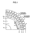
- a stator 1 is the same as that of the conventional structure, and is constituted by inserting and arranging U-phase stator coils U1, V-phase stator coils V1 and W-phase stator coils W1 to forty eight slots 3 formed in an annular stator iron coil 2.
- An opening portion 4 is formed in an inner peripheral portion of the stator iron core in correspondence to each of the slots.
- a rotor 6 is arranged in the stator 1 at a rotational gap and is structured such as to have auxiliary protruding poles in which a plurality of permanent magnets are arranged and fixed within a rotor iron core in a peripheral direction.
- the rotor 6 is constituted by fitting and adhering a stator iron core 7 to a rotary shaft 9 and inserting and assembling a permanent magnet 8 having a width (b) in a rotational direction, for example, made of neodymium to a rectangular punching hole having a width (a) in the rotational direction and formed in a peripheral direction of an outer peripheral portion of the rotor iron core 7 from an axial direction so that N-pole and S-pole are alternately arranged in respective receiving portions.
- the rotor 6 is rotatably arranged within the stator 1 in a state of having a predetermined rotational gap 5 with respect to an inner peripheral portion of the stator iron core 2.
- the rotor iron core 7 is constituted by laminating a multiplicity of silicon steel sheets on which holes for forming the receiving portions are formed.
- the width (a) in the rotational direction of the punching hole is larger than the width (b) in the rotational direction of the permanent magnet, and the space 10 generated by a difference between the lengths (a) and (b) is arranged in a direction of normal rotation, that is, a direction of forward movement of the hybrid electric vehicle.
- the maximum torque becomes different in the case of normal rotation and reverse rotation, that is, the normal rotation having the space 10 has a low torque and the reverse rotation has a high torque.
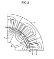
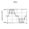
- Fig. 3 shows a distribution of a magnetic flux density of the rotational gap between P1 and P2 in the dynamo-electric machine in Fig. 2.
- the reverse rotation torque is larger than the normal rotation torque.
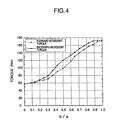
- Fig. 4 shows the forward movement torque and the backward movement torque in the case of changing the value b/a in the dynamo-electric machine shown in Fig. 2
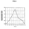
- Fig. 5 shows a relation between a ratio between the forward and backward movement torque (the backward movement torque/forward movement torque) and the value b/a.
- a reduction degree of the backward movement torque is smaller than that of the forward movement torque.
- the value b/a should be set to 0.5 to 0.9 in order to make the ratio between the forward and backward torque 1.05 to 1.2. If it is intended that the torque ratio is simply made 1.05 to 1.2, the value b/a 0.15 to 0.5 is sufficient, however, in this case, since the torque becomes too low as is apparent from Fig. 4, the value is improper.
- FIG. 6 shows an embodiment of a structure of a hybrid electric vehicle corresponding to a subject of the present invention.
- a drive system is mainly constituted by an engine 30, a motor 31 for driving an electric vehicle, a power generator 32 driven by the engine and used for charging a battery or the like, an inverter/converter 33, a battery 34, a drive shaft 37, a speed change gear (for example, a CVT) 35, and a clutch 36.
- the drive motor 31 since the drive motor 31 functions as a power generator for regeneration at a time of reducing speed, the drive motor 31 may be sometimes called as a dynamo-electric machine.
- the structure is made such that the engine 30, the clutch 36, the dynamo-electric machine (driving motor) 31, the speed change gear 35 and the drive shaft 37 are connected to each other in series, and the speed change gear 35 does not have a gear for switching the front and backward movements.
- the magnetic flux of the magnet is great, an iron loss becomes great and a weakening field current is increased since the magnetic flux amount is restricted, so that a performance is reduced.
- the torque in the backward movement side is secured, the insufficient torque at the low speed rotation time in the forward movement side is supplemented by an assistance of the engine, and the magnetic flux amount at the middle and high speed time is reduced, whereby it is possible to improve the performance such as an efficiency at the middle and high speed time or the like, and achieve a drive system suitable for the hybrid electric vehicle.
- the present invention can about 10% improve the rotational number in comparison with the conventional embodiment, and can about 1% improve the motor efficiency in the high speed side from 90% in the conventional one to 91% in the present invention.
- Fig. 9 shows a relation (in this case, between 0.5 and 1) between a ratio between the forward and backward movement torque (backward movement torque/forward movement torque) and the value b/a in the case of changing the value b/a in the dynamo-electric machine in Fig. 8.
- the value b/a is between 0.5 and 0.9 in order to make the forward and backward movement torque ratio between 1.05 and 1.2 even in the structure having 16 poles.
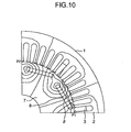
- the inclined angle ( ⁇ ) means an inclined angle with respect to a tangent line in a center (in a rotational direction) of the permanent magnet.
- Fig. 11 shows a distribution of a magnetic flux density of a rotational gap between P1 and P2 in the dynamo-electric machine in Fig. 10.
- the mechanical angle is 0 or 90 degrees
- the torque ratio becomes 1 due to a symmetrical property at each pole.
- the torque ratio becomes greatest due to most nonsymmetrical property.
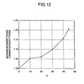
- Fig. 12 shows the inclined angle ( ⁇ ) and the ratio of the forward and backward movement torque. As is apparent from Fig. 12, when the angle ⁇ is set to 10 to 45 degrees, it is possible to make the ratio of the forward and backward torque between 1.05 and 1.2.
- the shape of the magnet is not limited to the rectangular shape shown in the first embodiment, but can employ various shapes such as an arc shape or the like.
- the permanent magnet 8 may employ the other magnets than the neodymium magnet, the number of (the number of the poles of) the permanent magnets may employ the other number than eight poles and sixteen poles, and the number of the slots of the stator may employ the other number than forty eight.
- the magnet is not limited to the inner rotation type and can be established by an outer rotation type.
- the ratio between the maximum torque output by the dynamo-electric machine at the normal rotation (forward movement) time and the torque output by the dynamo-electric machine at the reverse rotation (backward movement) time is 1 : 1.05 - 1.2 and becomes greater in the backward movement, it is possible to reduce the unnecessary torque (magnetic flux) at the normal rotation (forward movement) so as to improve the efficiency at the high speed and further improve the specific fuel consumption. Further, it is possible to provide the hybrid electric vehicle with compact, light and high efficiency which can output a predetermined torque at the backward movement.
Claims (8)
- Elektrisches Hybridfahrzeug, das eine dynamoelektrische Dauermagnetmaschine (31) verwendet, mit:einer dynamoelektrischen Dauermagnetmaschine (31), wobei die dynamoelektrische Dauermagnetmaschine (31) einen Stator (1) mit einem Statoreisenkern (2), um den eine Statorspule herumgewickelt ist, und einen Rotor (6) aufweist, der in dem Stator (1) in einem Rotationsspalt (5) angeordnet ist, mit mehreren Dauermagneten (8), die innerhalb eines Rotoreisenkerns (7) in Umfangsrichtung angeordnet und befestigt sind, und mit vorstehenden Hilfspolen;wobei die dynamoelektrische Maschine (31) und ein Motor (30) mit einer Antriebswelle (37) in Reihe verbunden sind; und kein Getriebe zum Umschalten zwischen Vorwärts- und Rückwärtsbewegungen vorgesehen ist;
dadurch gekennzeichnet, dass ein Verhältnis zwischen einer maximalen Drehmomentausgabe durch die dynamoelektrische Maschine (31), wenn sich das elektrische Fahrzeug vorwärts bewegt, und einem Drehmoment, das durch die dynamoelektrische Maschine (31) während einer Rückwärtsbewegung ausgegeben wird, eine Beziehung von 1:1,05 bis 1:1,2 herstellt, wobei das Drehmoment während der Rückwärtsdrehung größer als die maximale Drehmomentausgabe ist, wenn sich das elektrische Fahrzeug vorwärts bewegt, wobei eine Form in Umfangsrichtung des Rotors (6) an jedem Pol nicht-symmetrisch ist. - Elektrisches Hybridfahrzeug, das eine dynamoelektrische Dauermagnetmaschine (31) verwendet, nach Anspruch 1, wobei das Verhältnis zwischen der normalen und der Umkehrdrehung eine Beziehung von 1:1,05 bis 1:1,2 herstellt, wodurch das Drehmoment bei der Umkehrdrehung größer wird.
- Elektrisches Hybridfahrzeug, das eine dynamoelektrische Dauermagnetmaschine (31) verwendet, nach Anspruch 1 oder 2,
wobei eine Breite in Rotationsrichtung eines Dauermagnet-Einfügungslochs, das in dem Rotoreisenkern (7) vorgesehen ist, größer als eine Breite des Dauermagneten (8) ist und ein Raum (10), der durch einen Längenunterschied zwischen den beiden entsteht, in einer Vorwärtsbewegungsseite des elektrischen Fahrzeugs vorgesehen ist. - Elektrisches Hybridfahrzeug, das eine dynamoelektrische Dauermagnetmaschine (31) verwendet, nach Anspruch 1 oder 2,
wobei ein Dauermagnet-Einfügungsloch, das in dem Rotoreisenkern (7) vorgesehen ist, in einem vorgegebenen geneigten Winkel (θ) in Bezug auf die Umfangsrichtung vorgesehen ist, so dass ein Abstand von dem Rotationsspalt (5) in der normalen Rotationsseite der dynamoelektrischen Maschine (31) größer ist und der Dauermagnet (8) in das Einfügungsloch eingefügt wird. - Elektrisches Hybridfahrzeug, das eine dynamoelektrische Dauermagnetmaschine (31) verwendet, nach Anspruch 4, wobei der geneigte Winkel (θ) 10 bis 45 Grad beträgt (mechanischer Winkel).
- Elektrisches Hybridfahrzeug, das eine dynamoelektrische Dauermagnetmaschine (31) verwendet, nach Anspruch 1 bis 3, wobei eine Querschnittsform in Rotationsrichtung des Dauermagnet-Einfügungslochs und des Dauermagneten (8) eine rechtekkige Form ist.
- Elektrisches Hybridfahrzeug, das eine dynamoelektrische Dauermagnetmaschine (31) verwendet, nach Anspruch 1 bis 3, wobei eine Querschnittsform in Rotationsrichtung des Dauermagnet-Einfügungslochs und des Dauermagneten (8) eine Bogenform ist.
- Elektrisches Hybridfahrzeug, das eine dynamoelektrische Dauermagnetmaschine (31) verwendet, nach irgendeinem der Ansprüche 1 bis 7, wobei ein Verhältnis zwischen der Breite in Rotationsrichtung des Dauermagnet-Einfügungslochs, das in dem Rotoreisenkern (7) vorgesehen ist, und der Breite in Rotationsrichtung des Dauermagneten 1:0,5 bis 1:0,9 beträgt.
Applications Claiming Priority (2)
| Application Number | Priority Date | Filing Date | Title |
|---|---|---|---|
| JP2000061890A JP3403690B2 (ja) | 2000-03-02 | 2000-03-02 | 永久磁石式回転電機を用いたハイブリット電気自動車 |
| JP2000061890 | 2000-03-02 |
Publications (3)
| Publication Number | Publication Date |
|---|---|
| EP1130740A2 EP1130740A2 (de) | 2001-09-05 |
| EP1130740A3 EP1130740A3 (de) | 2002-10-02 |
| EP1130740B1 true EP1130740B1 (de) | 2008-01-23 |
Family
ID=18581968
Family Applications (1)
| Application Number | Title | Priority Date | Filing Date |
|---|---|---|---|
| EP00118187A Expired - Lifetime EP1130740B1 (de) | 2000-03-02 | 2000-08-30 | Elektrisches Hybridfahrzeug mit einer dynamoelektrischen Permanentmagnetmaschine |
Country Status (5)
| Country | Link |
|---|---|
| US (4) | US20020112904A1 (de) |
| EP (1) | EP1130740B1 (de) |
| JP (1) | JP3403690B2 (de) |
| KR (1) | KR20010087113A (de) |
| DE (1) | DE60037869T2 (de) |
Cited By (2)
| Publication number | Priority date | Publication date | Assignee | Title |
|---|---|---|---|---|
| CN101884156B (zh) * | 2007-11-15 | 2013-09-25 | 三菱电机株式会社 | 永磁型旋转电机及电动动力转向装置 |
| CN105584384A (zh) * | 2015-12-31 | 2016-05-18 | 清华大学苏州汽车研究院(吴江) | 一种纯电动车的四象限控制系统及其控制方法 |
Families Citing this family (17)
| Publication number | Priority date | Publication date | Assignee | Title |
|---|---|---|---|---|
| KR100425101B1 (ko) * | 2001-09-12 | 2004-03-30 | 엘지전자 주식회사 | 용량가변형 압축기용 모터 |
| JP4029817B2 (ja) * | 2003-10-10 | 2008-01-09 | 日産自動車株式会社 | 回転電機の磁気回路構造 |
| JP4581640B2 (ja) * | 2004-11-17 | 2010-11-17 | トヨタ自動車株式会社 | 車両駆動システムおよびそれを備える車両 |
| JP2006149031A (ja) * | 2004-11-17 | 2006-06-08 | Toyota Motor Corp | 車両駆動システムおよびそれを備える車両 |
| EP2128439A1 (de) | 2008-05-27 | 2009-12-02 | Syneola SA | Intelligentes dezentralisiertes elektrisches Stromerzeugungssystem |
| JP5457079B2 (ja) * | 2008-12-17 | 2014-04-02 | アスモ株式会社 | ブラシレスモータ |
| JP5806073B2 (ja) * | 2010-10-19 | 2015-11-10 | アスモ株式会社 | ブラシレスモータ |
| JP2012110213A (ja) * | 2010-10-25 | 2012-06-07 | Asmo Co Ltd | モータ |
| JP5664165B2 (ja) * | 2010-11-18 | 2015-02-04 | トヨタ自動車株式会社 | 電動車両 |
| CN103339003B (zh) | 2011-02-09 | 2016-04-06 | 铃木株式会社 | 用于混合动力车辆的驱动源控制装置、用于混合动力车辆的驱动源控制方法和混合动力车辆 |
| KR101940755B1 (ko) * | 2012-01-16 | 2019-01-21 | 삼성전자 주식회사 | 회전자 및 이를 포함하는 전동기 |
| KR101427944B1 (ko) * | 2012-12-31 | 2014-08-11 | 현대자동차 주식회사 | 동기모터의 스테이터 |
| US9634530B2 (en) * | 2013-03-15 | 2017-04-25 | Steering Solutions Ip Holding Corporation | Interior permanent magnet motor with shifted rotor laminations |
| JP6172114B2 (ja) * | 2014-10-28 | 2017-08-02 | トヨタ自動車株式会社 | ハイブリッド自動車 |
| JP6390506B2 (ja) | 2015-04-28 | 2018-09-19 | 株式会社デンソー | 回転電機のロータ |
| DE102015220430A1 (de) * | 2015-10-20 | 2017-04-20 | Zf Friedrichshafen Ag | Kraftfahrzeug |
| JP6249433B1 (ja) * | 2017-02-28 | 2017-12-20 | 三菱電機株式会社 | 横流電流検出装置、横流電流検出方法、および、回転子 |
Family Cites Families (27)
| Publication number | Priority date | Publication date | Assignee | Title |
|---|---|---|---|---|
| US4028965A (en) * | 1974-12-09 | 1977-06-14 | Ford Motor Company | Multiple ratio power transmission mechanism adapted for improved engine fuel economy and high/low ratio traction |
| JPS55127221A (en) * | 1979-03-20 | 1980-10-01 | Daihatsu Motor Co Ltd | Driving system of vehicle |
| US4438362A (en) * | 1982-08-19 | 1984-03-20 | Rotron, Incorporated | Self-starting, direct current motor with permanent magnets of varied magnetic strength |
| US5343970A (en) * | 1992-09-21 | 1994-09-06 | Severinsky Alex J | Hybrid electric vehicle |
| JP3457357B2 (ja) * | 1993-07-23 | 2003-10-14 | 株式会社日立製作所 | スペクトル拡散通信システム、送信電力制御方法、移動端末装置及び基地局 |
| JP2968918B2 (ja) * | 1993-09-16 | 1999-11-02 | 弘平 湊 | 磁力回転装置 |
| DE4339703A1 (de) * | 1993-11-22 | 1995-05-24 | Schloetzer Eugen | Verfahren zur Verminderung des Energieverbrauchs von Hybridantrieben |
| DE4342735A1 (de) * | 1993-12-15 | 1995-06-22 | Hoehn Bernd Robert Prof Dr | Hybrid-Antriebsanordnung |
| US5603096A (en) * | 1994-07-11 | 1997-02-11 | Qualcomm Incorporated | Reverse link, closed loop power control in a code division multiple access system |
| JPH0833246A (ja) * | 1994-07-20 | 1996-02-02 | Yaskawa Electric Corp | 永久磁石形同期回転電機のロータ |
| GB2294168A (en) * | 1994-10-15 | 1996-04-17 | Nokia Telecommunications Oy | Multi-channel transmitters for radio telephone base stations |
| US5703902A (en) * | 1995-06-16 | 1997-12-30 | Qualcomm Incorporated | Method and apparatus for determining signal strength in a variable data rate system |
| JP3449061B2 (ja) * | 1995-09-19 | 2003-09-22 | 株式会社デンソー | 直流モータ |
| JP3216501B2 (ja) * | 1995-10-13 | 2001-10-09 | トヨタ自動車株式会社 | ハイブリッド駆動装置 |
| EP0823771B1 (de) * | 1996-02-23 | 2006-04-26 | Matsushita Electric Industrial Co., Ltd. | Motor |
| JP3531332B2 (ja) * | 1996-02-29 | 2004-05-31 | トヨタ自動車株式会社 | ハイブリッド駆動装置 |
| JP3347935B2 (ja) * | 1996-03-29 | 2002-11-20 | 株式会社日立製作所 | 永久磁石回転電機及びそれを用いた電動車両 |
| US5811904A (en) * | 1996-03-21 | 1998-09-22 | Hitachi, Ltd. | Permanent magnet dynamo electric machine |
| US5989146A (en) * | 1997-03-21 | 1999-11-23 | New Venture Gear, Inc. | On-demand four-wheel drive transmission |
| US5987333A (en) * | 1997-09-30 | 1999-11-16 | Nortel Networks Corporation/Corporation Nortel Networks | Communications power control |
| DE19747265B4 (de) * | 1997-10-25 | 2010-11-04 | Zf Friedrichshafen Ag | Hybridantrieb für ein Fahrzeug |
| US6545986B1 (en) * | 1997-12-31 | 2003-04-08 | Verizon Laboratories Inc. | CDMA forward link power control |
| JPH11280512A (ja) * | 1998-03-30 | 1999-10-12 | Nissan Motor Co Ltd | ハイブリッド車両 |
| JP3451935B2 (ja) * | 1998-06-03 | 2003-09-29 | 日産自動車株式会社 | ハイブリッド車両の駆動力制御装置 |
| US6232733B1 (en) * | 1998-07-28 | 2001-05-15 | Denso Corporation | Engine-motor hybrid vehicle control apparatus and method having power transmission device operation compensation function |
| US6151328A (en) * | 1998-12-31 | 2000-11-21 | Lg Information & Communications Ltd. | Apparatus and method for controlling power in code division multiple access system |
| US6590873B1 (en) * | 1999-02-05 | 2003-07-08 | Lucent Technologies Inc. | Channel structure for forward link power control |
-
2000
- 2000-03-02 JP JP2000061890A patent/JP3403690B2/ja not_active Expired - Lifetime
- 2000-08-30 DE DE60037869T patent/DE60037869T2/de not_active Expired - Fee Related
- 2000-08-30 EP EP00118187A patent/EP1130740B1/de not_active Expired - Lifetime
- 2000-09-04 KR KR1020000052073A patent/KR20010087113A/ko not_active Application Discontinuation
-
2002
- 2002-02-08 US US10/067,938 patent/US20020112904A1/en not_active Abandoned
-
2003
- 2003-11-21 US US10/717,474 patent/US20040112655A1/en not_active Abandoned
-
2006
- 2006-08-15 US US11/503,973 patent/US20060272870A1/en not_active Abandoned
- 2006-12-14 US US11/610,578 patent/US20070084652A1/en not_active Abandoned
Cited By (3)
| Publication number | Priority date | Publication date | Assignee | Title |
|---|---|---|---|---|
| CN101884156B (zh) * | 2007-11-15 | 2013-09-25 | 三菱电机株式会社 | 永磁型旋转电机及电动动力转向装置 |
| CN105584384A (zh) * | 2015-12-31 | 2016-05-18 | 清华大学苏州汽车研究院(吴江) | 一种纯电动车的四象限控制系统及其控制方法 |
| CN105584384B (zh) * | 2015-12-31 | 2018-06-19 | 清华大学苏州汽车研究院(吴江) | 一种纯电动车的四象限控制方法 |
Also Published As
| Publication number | Publication date |
|---|---|
| EP1130740A3 (de) | 2002-10-02 |
| KR20010087113A (ko) | 2001-09-15 |
| US20020112904A1 (en) | 2002-08-22 |
| DE60037869T2 (de) | 2009-01-22 |
| US20060272870A1 (en) | 2006-12-07 |
| US20040112655A1 (en) | 2004-06-17 |
| JP2001251703A (ja) | 2001-09-14 |
| US20070084652A1 (en) | 2007-04-19 |
| EP1130740A2 (de) | 2001-09-05 |
| JP3403690B2 (ja) | 2003-05-06 |
| DE60037869D1 (de) | 2008-03-13 |
Similar Documents
| Publication | Publication Date | Title |
|---|---|---|
| US20060272870A1 (en) | Hybrid electrical vehicle employing permanent magnetic type dynamo-electric machine | |
| US7151335B2 (en) | Permanent magnet rotating electric machine and electric car using the same | |
| CN102474143B (zh) | 车辆用旋转电机 | |
| EP2184838B1 (de) | Motor des axialspalttyps | |
| US6759778B2 (en) | Electric vehicle using a motor | |
| JP4818368B2 (ja) | ハイブリッド車両 | |
| EP1253701B1 (de) | Motor | |
| JP4319961B2 (ja) | 回転電機及び電機巻線 | |
| EP1130747B1 (de) | Elektrische Machine mit Dauermagneten für ein elektrisches Hybrydfahrzeug | |
| US7969057B2 (en) | Synchronous motor with rotor having suitably-arranged field coil, permanent magnets, and salient-pole structure | |
| EP1505714A1 (de) | Elektrische dynamomaschine | |
| JP2000125525A (ja) | 車両用駆動装置 | |
| JP3752487B2 (ja) | ハイブリッド車及び回転電機 | |
| JPH08205437A (ja) | 同期電動機 | |
| JP2010068605A (ja) | 永久磁石回転電機 | |
| JP2001339923A (ja) | モータ | |
| EP3826145A1 (de) | Elektrische drehmaschine, antriebssystem für elektrische drehmaschine und elektrofahrzeug | |
| JP2023142395A (ja) | 動力装置 |
Legal Events
| Date | Code | Title | Description |
|---|---|---|---|
| PUAI | Public reference made under article 153(3) epc to a published international application that has entered the european phase |
Free format text: ORIGINAL CODE: 0009012 |
|
| AK | Designated contracting states |
Kind code of ref document: A2 Designated state(s): AT BE CH CY DE DK ES FI FR GB GR IE IT LI LU MC NL PT SE |
|
| AX | Request for extension of the european patent |
Free format text: AL;LT;LV;MK;RO;SI |
|
| PUAL | Search report despatched |
Free format text: ORIGINAL CODE: 0009013 |
|
| RIC1 | Information provided on ipc code assigned before grant |
Free format text: 7H 02K 1/27 A, 7H 02K 21/14 B, 7H 02K 21/02 B, 7B 60K 6/04 B, 7B 60L 11/12 B |
|
| AK | Designated contracting states |
Kind code of ref document: A3 Designated state(s): AT BE CH CY DE DK ES FI FR GB GR IE IT LI LU MC NL PT SE |
|
| AX | Request for extension of the european patent |
Free format text: AL;LT;LV;MK;RO;SI |
|
| 17P | Request for examination filed |
Effective date: 20030129 |
|
| AKX | Designation fees paid |
Designated state(s): DE FR GB |
|
| 17Q | First examination report despatched |
Effective date: 20061204 |
|
| GRAP | Despatch of communication of intention to grant a patent |
Free format text: ORIGINAL CODE: EPIDOSNIGR1 |
|
| GRAS | Grant fee paid |
Free format text: ORIGINAL CODE: EPIDOSNIGR3 |
|
| GRAA | (expected) grant |
Free format text: ORIGINAL CODE: 0009210 |
|
| RIN1 | Information on inventor provided before grant (corrected) |
Inventor name: OBARA, SANSHIRO,HITACHI LTD. INTELLECTUAL PROPERTY Inventor name: KOIZUMI, OSAMU,HITACHI LTD. INTELLECTUAL PROPERTY Inventor name: KAWAMATA, SHOUICHI,HITACHI LTD. INTELLECTUAL PROPE Inventor name: TAJIMA, FUMIO,HITACHI LTD., INTELLECTUAL PROPERTY Inventor name: MATSUNOBU, YUTAKA,HITACHI LTD., INTELLECTUAL PROPE |
|
| RAP1 | Party data changed (applicant data changed or rights of an application transferred) |
Owner name: HITACHI, LTD. |
|
| AK | Designated contracting states |
Kind code of ref document: B1 Designated state(s): DE FR GB |
|
| REG | Reference to a national code |
Ref country code: GB Ref legal event code: FG4D |
|
| RIC1 | Information provided on ipc code assigned before grant |
Ipc: B60L 11/12 20060101ALI20071220BHEP Ipc: B60K 6/20 20071001ALI20071220BHEP Ipc: H02K 21/02 20060101ALI20071220BHEP Ipc: H02K 21/14 20060101ALI20071220BHEP Ipc: H02K 1/27 20060101AFI20071220BHEP |
|
| REF | Corresponds to: |
Ref document number: 60037869 Country of ref document: DE Date of ref document: 20080313 Kind code of ref document: P |
|
| PGFP | Annual fee paid to national office [announced via postgrant information from national office to epo] |
Ref country code: DE Payment date: 20080831 Year of fee payment: 9 |
|
| PGFP | Annual fee paid to national office [announced via postgrant information from national office to epo] |
Ref country code: FR Payment date: 20080819 Year of fee payment: 9 |
|
| PLBE | No opposition filed within time limit |
Free format text: ORIGINAL CODE: 0009261 |
|
| STAA | Information on the status of an ep patent application or granted ep patent |
Free format text: STATUS: NO OPPOSITION FILED WITHIN TIME LIMIT |
|
| 26N | No opposition filed |
Effective date: 20081024 |
|
| PGFP | Annual fee paid to national office [announced via postgrant information from national office to epo] |
Ref country code: GB Payment date: 20080620 Year of fee payment: 9 |
|
| GBPC | Gb: european patent ceased through non-payment of renewal fee |
Effective date: 20090830 |
|
| REG | Reference to a national code |
Ref country code: FR Ref legal event code: ST Effective date: 20100430 |
|
| PG25 | Lapsed in a contracting state [announced via postgrant information from national office to epo] |
Ref country code: FR Free format text: LAPSE BECAUSE OF NON-PAYMENT OF DUE FEES Effective date: 20090831 Ref country code: DE Free format text: LAPSE BECAUSE OF NON-PAYMENT OF DUE FEES Effective date: 20100302 |
|
| PG25 | Lapsed in a contracting state [announced via postgrant information from national office to epo] |
Ref country code: GB Free format text: LAPSE BECAUSE OF NON-PAYMENT OF DUE FEES Effective date: 20090830 |