EP1127817B1 - Machine pour séparer des produits plats - Google Patents
Machine pour séparer des produits plats Download PDFInfo
- Publication number
- EP1127817B1 EP1127817B1 EP01810175A EP01810175A EP1127817B1 EP 1127817 B1 EP1127817 B1 EP 1127817B1 EP 01810175 A EP01810175 A EP 01810175A EP 01810175 A EP01810175 A EP 01810175A EP 1127817 B1 EP1127817 B1 EP 1127817B1
- Authority
- EP
- European Patent Office
- Prior art keywords
- separating
- objects
- crab
- stage
- initial
- Prior art date
- Legal status (The legal status is an assumption and is not a legal conclusion. Google has not performed a legal analysis and makes no representation as to the accuracy of the status listed.)
- Expired - Lifetime
Links
Images


Classifications
-
- B—PERFORMING OPERATIONS; TRANSPORTING
- B65—CONVEYING; PACKING; STORING; HANDLING THIN OR FILAMENTARY MATERIAL
- B65H—HANDLING THIN OR FILAMENTARY MATERIAL, e.g. SHEETS, WEBS, CABLES
- B65H3/00—Separating articles from piles
- B65H3/46—Supplementary devices or measures to assist separation or prevent double feed
- B65H3/52—Friction retainers acting on under or rear side of article being separated
- B65H3/5246—Driven retainers, i.e. the motion thereof being provided by a dedicated drive
-
- B—PERFORMING OPERATIONS; TRANSPORTING
- B65—CONVEYING; PACKING; STORING; HANDLING THIN OR FILAMENTARY MATERIAL
- B65H—HANDLING THIN OR FILAMENTARY MATERIAL, e.g. SHEETS, WEBS, CABLES
- B65H1/00—Supports or magazines for piles from which articles are to be separated
- B65H1/02—Supports or magazines for piles from which articles are to be separated adapted to support articles on edge
- B65H1/025—Supports or magazines for piles from which articles are to be separated adapted to support articles on edge with controlled positively-acting mechanical devices for advancing the pile to present the articles to the separating device
-
- B—PERFORMING OPERATIONS; TRANSPORTING
- B65—CONVEYING; PACKING; STORING; HANDLING THIN OR FILAMENTARY MATERIAL
- B65H—HANDLING THIN OR FILAMENTARY MATERIAL, e.g. SHEETS, WEBS, CABLES
- B65H3/00—Separating articles from piles
- B65H3/02—Separating articles from piles using friction forces between articles and separator
- B65H3/06—Rollers or like rotary separators
- B65H3/0653—Rollers or like rotary separators for separating substantially vertically stacked articles
-
- B—PERFORMING OPERATIONS; TRANSPORTING
- B65—CONVEYING; PACKING; STORING; HANDLING THIN OR FILAMENTARY MATERIAL
- B65H—HANDLING THIN OR FILAMENTARY MATERIAL, e.g. SHEETS, WEBS, CABLES
- B65H2403/00—Power transmission; Driving means
- B65H2403/70—Clutches; Couplings
- B65H2403/72—Clutches, brakes, e.g. one-way clutch +F204
-
- B—PERFORMING OPERATIONS; TRANSPORTING
- B65—CONVEYING; PACKING; STORING; HANDLING THIN OR FILAMENTARY MATERIAL
- B65H—HANDLING THIN OR FILAMENTARY MATERIAL, e.g. SHEETS, WEBS, CABLES
- B65H2511/00—Dimensions; Position; Numbers; Identification; Occurrences
- B65H2511/50—Occurence
- B65H2511/51—Presence
Definitions
- the present invention relates to a machine according to the preamble of patent claim 1.
- the present invention has for its object to provide a machine of the type mentioned for separating objects arranged in a stack, which is powerful and easy to handle and can be easily inserted between different working processes.
- the objects are fed horizontally to a transfer room, there isolated and then output vertically downwards for further processing. Due to slight adaptations of the machine, the output of the separated objects can also be made in other directions. Loading the machine with the separation material is possible without special measures and in particular requires no interruption in operation.
- a particular advantage of the invention is that no individual adjustment is necessary for different thicknesses and formats of the articles, which results in easy handling and reliable operation.
- a vertically adjustable in height console allows to adjust the height of fall of the isolated objects depending on their dimensions or due to the requirements of the subsequent further processing units arbitrarily. After leaving the machine, the items are immediately free and can continue are processed. It can be used autonomously or easily in conjunction with other units of a processing chain, such as a dispenser for envelopes for inserting or franking machines, or as a paper dispenser for folding machines or printers, or as a dispenser for a packaging line for Compact discs.
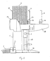
- FIG. 1 to 4 show the basic structure of the inventive machine.
- FIGS. 1 and 2 each show a view from the side of the entire machine with a stack of articles 2 with a small format or of objects 5 with a larger format, which are passed to a further processing unit after separation.
- the feeding of the articles 2.5 is carried out with a horizontally displaceable trolley 10 with a headband 6.
- the headband 6 and another headband 29 at the opposite end of the stack prevent the tilting of the stack.
- the items to be separated are envelopes 2, 5 fed from a stack.
- Figs. 1 and 2 an envelope 2 and 5, respectively, has been singulated and dispensed.
- the machine is supported by a console 30 with a vertical support 49. Their height above the base is by means provided on both sides hand screws 3 to 4 guides the wearer 49 adjustable. Double-sided covers 14 cover parts of the machine drive and protect it from contamination.
- Fig. 3 shows a view from the side into the machine and Fig. 4 shows a view from above of the machine.
- the viewer facing hood 14 Figures 1 and 2) and the side wall 7B of a frame 7 is omitted.
- Cross sections 8A ... 8F connect the side walls 7A and 7B and form with these the frame 7.
- the frame 7 parallel to the side walls 7A, 7B extending longitudinal profiles 50, 51 which serve as a support for the stack and as slide rails for the Trolley 10 serve.
- at least one guide shaft 9 is inserted in the frame 7.
- the trolley 10 is guided with two plain bearings 11 of the guide shaft 9.
- a drive shaft 12 drives two on rollers 42A, 42B circulating belt 13.
- the rollers 42A are arranged on the drive shaft 12 and the rollers 42B on a shaft 66.
- the belts 13 are connected to the trolley 10 with fastening means 52.
- the trolley 10 has a stop 32 and a spring system 23 with a spring 33 and a U-shaped spring holder 34.
- the stop 32 is connected via the spring system 23 in all directions freely movable with the trolley 10 and is pushed against the trolley 10 during compression of the spring 33.
- the sprung stop 32 in conjunction with a pre-separation stage 36 ensures gentle pressure in the transfer space 31.
- the drive of the machine is only indicated for reasons of clarity. He is left and right outside on the side walls 7A, 7B distributed under the hoods 14. Details of the drive will be described below with reference to FIG. 7.
- FIG. 5a shows details of the singulation in a sectional view and FIG. 5b in a plan view.
- the separation has two superimposed identically constructed separation stages 37 and 38. These essentially consist of a separating element V1 or V2 and a separating roller 18 or 18A arranged at the same height.
- the separating rollers 18 and 18A are arranged on separating shafts 17 and 17A, respectively.
- the separating element V essentially consists of 3 parts, namely a sleeve 53 with rubber coating 60, an adjusting sleeve 54 and a wrap spring 55 mounted on a shaft 25 are arranged.
- Sleeve 53 and adjusting sleeve 54 are preferably made of plastic. Their bore also serves as a bearing on the shaft 25.
- Both sleeves 53, 54 are secured with a fine toothing 56 against rotation.
- the sleeves 53, 54 can be extended axially. As a result, the toothing 56 can be adjusted until the wrap spring 55, which is slightly oversize and one in diameter with respect to the shaft 25 has larger Windungsreserve has reached the desired torque. Both ends of the wrap spring 55 are fixed to the sleeves.
- the sleeves 53, 54 are then axially compressed and snap. The torque of the separating element V can be adjusted in this way as needed.
- the separating element V can rotate in a direction of rotation to a certain desired torque, i. be set to a freewheel with a certain rotational resistance.
- the sleeve 53 can rotate on the shaft 25 in one direction with a freewheel determined by the torque.
- the sleeve 53 is blocked according to the principle of a wrap spring clutch and can not rotate.
- the shaft 25 of the upper separating element V1 ( Figure 5) is driven by a propeller shaft 41. It is mounted in a holder 26 fixed to the frame 7 and can move slightly in the radial direction (for example by about 7 mm).
- a spring 27 allows this movement and the necessary pressure force can be adjusted by acting on the spring 27 knurled nut 28.
- the pressure between the separating roller 18 and the separating element V1 and the torque of the separating element V1 must have a certain relationship to one another. If there are no sheets in between, the singling roller 18 must still be able to drive the singling element V1 slightly, i. the separating element V1 must rotate with it. The correct function of the singling is ensured if, by appropriate adjustment of the knurled nut 28, the friction between two successive envelopes (B1 and B2 in FIG. 5a) is smaller than the torque of the singling element V1, i. In this case, the envelope B1 must grind on the envelope B2 and the envelope B2 remains together with the separating element V1 or is pushed back and then stands still until the envelope B1 has completely passed through the separating stage 37. In principle, the same applies to the separating element V2 and the separating roller 18A of the lower separating stage 38, in which the shaft 25A of the separating element V2 is driven by a cardan shaft 41A.
- FIG. 9a shows the mode of action when a single envelope B1 enters a singling stage, for example into the upper singling stage 37 of FIG.
- the separating shaft 17 and the shaft 25 rotate clockwise.
- the separating element V1 rotates counterclockwise with an adjustable freewheel. If the roller 18 and the separating element V1 are pressed against each other by the spring 27 (FIG. 5a), the roller 18 forces the opposite separating element V1 to rotate counterclockwise.
- FIG. 9b illustrates the behavior of a singulation stage when several items arrive simultaneously in this area.
- the set torque of the separating element V1 is greater than the friction between the envelopes B1 and B2. Therefore, the separating element V1 pushes back the envelopes under the uppermost envelope B1.
- the uppermost envelope B1 is pushed forward unhindered and passes over the underlying envelope B2.
- the case of Fig. 9a reenters.
- the second (lower) separating stage 38 consists of a separating roller 18A with a shaft 17A and a separating element V2 which is constructed identically to the separating element V1 of the separating stage 37.
- the separating rollers 18 and 18A are in the running direction of the articles (in Fig. 3 and Fig.
- the freewheeling direction corresponds to the direction of rotation of the separating shafts 17 and 17A of the separating rollers 18 and 18A. In the other direction, the separating rollers 18, 18A are fixedly coupled to the separating shaft 17 and 17A, respectively.
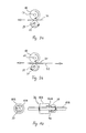
- a preclearing stage 36 is provided in the machine. Details of pre-singulation stage 36 are shown in FIG. It consists of a pre-separating shaft 17B, of a pre-separating roller 18B free-wheeling in both directions of rotation on the shaft 17B and of a freewheel sleeve 39.
- the shaft 17B is rotatably mounted on both sides on arms 20, 20A (FIG.
- the arms 20, 20A are articulated, for example on the separating shaft 17.
- the pre-separating shaft 17B forms a rocker 64 with the arms 20, 20A.
- the free-wheeling sleeve 39 is disposed adjacent to the pre-dicing roller 18B on the pre-dicing shaft 17B. It is only in the direction of the objects to be separated, in Fig. 3 down on the pre-dicing shaft 17 B free-running, ie rotatable.
- the Vorierzelungsrolle 18 B and the freewheel sleeve 39 each have a driver pin 40 A and 40 (FIG. 10), which are arranged axially at the same distance from the shaft 17 B and directed against each other.
- the pre-separating roller 18B like the separating rollers 18, 18B, is preferably provided with a rubber coating.
- the pre-separation stage 36 has essentially the following two functions: First, it controls the switching on and off of the feed of the trolley 10 via the rocker 64. Second, it ensures that the first (foremost) envelope from the stack in the transfer space 31 with a certain pressure in the upper separation stage 37 with the singling roller 18 and the separating element V1 passes (Fig. 3). Since the separating element V1 and the separating roller 18 have a greater common peripheral speed than the pre-separating roller 18B, the pre-separating roller 18B - driven by the envelope - rotates faster than the pre-separating shaft 17B. Therefore, the driver pin 40A protruding from the pre-separating roller 18B (FIG.
- FIG. 7 details of the drive of the machine are shown in two side views and in a plan view.
- the plan view is two-dimensional, for convenience of understanding. executed in one level.
- a side mounted engine 15 drives a motor shaft 16.
- the separating shafts 17, 17A, the Vorierzelungswelle 17B and the feed of the trolley 10 are driven.
- the separating shaft 17A and the cardan shafts 41 (FIG. 5b) are driven by the separating shaft 17 in a ratio of 1: 1.
- the shaft 17B runs in a ratio of 1: 3.5 slower than the shaft 17.
- the drive for the trolley 10 has its origin in the separating shaft 17 and runs along the dashed line in the direction of arrow D to the shaft 12.
- the drive for the separating shafts 17, 17A , 17B has its origin at the motor shaft 16 and runs along the dashed line in the direction of arrow C.
- the branching of the drive takes place at the gears 102, 103, which are firmly connected.
- a particular advantage of the machine drive shown is that only one motor 15 is necessary for all functions of the machine.
- the spring 21 is tensioned.
- the switch 22 is arranged with respect to the rocker 64 so that the pressure of the stack on the Vorzerzelungsrolle 18 B and thus on the rocker 64 can not exceed a certain value. This ensures that the foremost envelope of the stack is never pinched between the stack and the pre-separation roller 18B and thereby can block the singulation process.
- the rocker 64 reaches the position ST2
- the switch 22 switches off the electric clutch 19 and the movement of the trolley 10 is stopped.
- the stopper 32 then only exercises a support function for the stack. As soon as the pressure of the stack on the pre-separating roller 18B falls below a certain value in the course of the singling process, the feed of the trolley 10 is switched on again by the switch 22 via the electric clutch 19.
- the trolley 10 can be pushed by hand in both directions. This simplifies the loading of the stack, especially for reloading during operation of the machine.
- the trolley 10 is initially pushed all the way to the stack and ensures at all times to keep the stack upright. After deduction of the last Breifumschlag from the stack of the stopper 32 touches the Vorierzelungsrolle 18B. Finally, the rocker 64 stops via the switch 22, the feed of the trolley 10th
- FIG. 8 shows a further possible application of the machine according to the invention.
- the stacked envelopes are guided by the trolley 10 vertically from bottom to top to the transfer room.
- the feeder, pre-separation stage 36 and singulation stages 37, 38 are rotated 90 degrees up from the previously described example.
- the separation of the envelopes takes place from the top of the stack and the envelopes are issued individually in the horizontal direction.
- the stop 32 and the spring system 23 with the spring 33 and the spring holder 34 can be omitted here.
- an electrical circuit board 35 which contains a counter.
- a photocell exiting the envelopes from the machine controls the sequence of the machine.
- the start / stop operation of the machine may, for example, be controlled by a postage meter via a photocell.
- the machine described is not only suitable for separating envelopes, but quite generally for separating sheet-like objects with different thicknesses and with a wide variety of formats.
- objects such as paper sheets from 70 to 160 grams / m2, empty or filled envelopes in the open or closed state, labels on carrier paper, compact discs, etc. can be easily processed up to a thickness of about 6 mm.
- the stack to be processed can be any length. If the stack is short, the machine can also work without mechanical stack feed. In this case, the machine must be inclined by about 45 ° in the direction of the singulation stage, e.g. in a processing line consisting i.a. from a printer and an inserter, the machine being inserted as a buffer between the printer and the inserter.
- the stack is advanced solely by its own weight on the longitudinal profiles 50, 51.
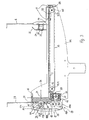
- FIG. 11 and 12 show another embodiment of the machine, wherein Fig. 11 is a sectional view of the plan view of Fig. 12.
- This embodiment is particularly suitable for the safe separation of relatively thin and flexible objects, such as paper sheets 5 (stationery). It differs from the previously described machine essentially by a built-in chain guide unit 44 and by a single separation stage 43.
- the chain guide unit 44 has at least two parallel to the guide shaft 9 extending circulation chains 57, 58.
- circulation chains 57, 58 is a roller chain, as used for example in bicycles.
- On each side of the guide shaft 9, a circulation chain 57 and 58 is provided.
- the circulating chains 57, 58 are supported by rails 71A, 71B via their links - for example plates arranged vertically parallel to the guide shaft 9 - and are free-running on the rails 71, 71A in both directions parallel to the guide shaft 9.
- the rails 71, 71A are fixed to cross members 75A, 75B on the frame 7. They simultaneously serve as a guideway for the trolley 46.
- the rails 71 A, 71 B laterally each have a horizontally mounted support 74 A, 74 B, on which the trolley 46 can slide.
- the circulating chains 57, 58 replace the longitudinal profiles 50, 51 in the previously described embodiment as a support for the leaves fifth
- the trolley 46 the drive is designed in principle the same as in the embodiment according to FIG. 1ff, has a headband 59, which is articulated via a tension spring 47. Of the Holding bracket 59 can therefore to the rear - in Fig. 11 to the right - evade. This allows unimpeded reloading of the stack with sheets 5 even during operation of the machine.
- a chain tensioner 45 prevents the orbital chains 57, 58 from becoming loose.
- the stack with the sheets to be separated 5 is directly on the circulating chains 57, 58 between the headband 59 and another holder 61 in the region of the separation. The stack is moved by the trolley 46 in the direction of the separation.
- the simplified separation consists essentially of a pre-separation stage 77 and a separation stage 43, which are identical in structure and function as the pre-separation stage 36 and the separation stage 37 in Fig. 3. Likewise, their arrangement in the machine as with reference to Fig. 3ff described.
- a Vorierzelungsrolle 62 and next to a freewheel sleeve with oppositely directed driving pins corresponding to FIG. 10 are arranged.
- the pre-separating roller 62 and the separating roller 63 are disposed on transverse shafts 72, 73 which are rotatably mounted on the rocker 76.
- the rocker 76 is pivotally mounted at the pivot point 65 via the shaft 73 on the frame 7 and connected to a mounted on the frame 7 spring 21.
- the separating element V1 is also attached, the pressure against the separating roller 63 can be adjusted with a knurled nut 69 and a spring 68.
- On frame 7 is still at least approximately over the entire width of the machine extending sliding plate 70 is attached.
- the drive for the feed of the trolley 46 and the various elements of the separation are identical to the drive in the previously described embodiment of the machine.
- the foremost sheets 5 advance into the transfer space 31 as the stack advances and stand vertically on the slide plate 70.
- the leading sheet is pushed down by the pre-separation roller 62 between the singling roller 63 and the singulator V1, and then taken up ejected in the direction of the arrow.
- the separation of the sheets 5 reaching into the transfer space 31 basically proceeds in the same way as in the embodiment described with reference to FIG. 3ff.
- the embodiment of the machine according to FIGS. 11 and 12 uses the same basic structure with the frame 7, the carrier 49, the feed for the trolley 10 and the transmission with the motor 15 as the machine according to FIG. 1ff.
- the chain guide assembly 44 can be incorporated as a module if desired with the rails 71A, 71B attached to the frame 7 and replacing the longitudinal profiles 50, 51 (FIG. 4).
- the simplified singling with the pre-separating roller 62 and the singling stage 43 can readily be installed instead of the singling according to FIG.
- the drive of the machine according to FIG. 3ff can be taken over unchanged for this embodiment.
- the machine can be easily adapted to changing requirements with respect to the items to be separated.
- the different variants for the output direction of the separated objects open up a variety of possible applications of the machine. Thanks to this diversity, the machine can be adapted to the most diverse requirements in complex processing chains. Thus, a processing of stacks is possible in which objects with different formats and different thickness are included.
Landscapes
- Engineering & Computer Science (AREA)
- Mechanical Engineering (AREA)
- Sheets, Magazines, And Separation Thereof (AREA)
- Sorting Of Articles (AREA)
- Pile Receivers (AREA)
- Processing And Handling Of Plastics And Other Materials For Molding In General (AREA)
- Combined Means For Separation Of Solids (AREA)
Claims (18)
- Machine pour séparer des objets (2;5) plats contenu dans un entrepôt, avec- une unité d'avance (9,12,13,19) avec un palan (10) pour amener les objets (2;5),- une section de pré-séparation (36;77) pour recevoir les objets (2;5) amenés et pour la transmission des objets (2;5) pièce par pièce,- au moins une section de séparation (37;43) pour recevoir les objets (2;5) reçus de la section de pré-séparation (36;77) et pour la délivrance des objets (2;5) pièce par pièce,- une unité de propulsion (15,16,17) pour l'unité d'avance (9,12,13,19), pour la section de pré-séparation (36;77) et pour les sections de séparation (37,38;43),caractérisée par le fait que l'unité de propulsion (15,16,17) interrompt l'avancement du palan (10), lorsque dans l'espace de remise (31) entre le palan (10) et la section de pré-séparation (36;77) la quantité d'objets (2;5) excède une valeur déterminée.
- Machine selon la revendication 1, caractérisée par le fait qu' il sont prévus deux sections de séparation (37,38).
- Machine selon la revendication 1 ou 2, caractérisée par le fait que les sections de séparation (37,38;43) contiennent un calandre de séparation (18,18A;63) fixé sur un cylindre de séparation (17,17A ;73) et un élément de séparation (V1,V2) opposé, et que les calandres de séparation (18,18A;63) contiennent un marche libre dans le sens du mouvement des objets (2;5).
- Machine selon la revendication 3, caractérisée par le fait que la pression d'un élément de séparation (V1,V2) sur le calandre de séparation (18,18A;63) opposé est ajustable.
- Machine selon la revendication 3 ou 4, caractérisée par le fait que l'élément de séparation (V1,V2) se compose d'une douille (53) et d'une douille (54) ajustable avec engrenages qui s'engrènent et d'un ressort (55) à collet et d'un cylindre (25).
- Machine selon la revendication 1, caractérisée par le fait que la section de pré-séparation (36;77) comporte un calandre de pré-séparation (18B;62) marchant libre dans les deux senses de rotation et avec une cheville d'emportement (40A) sortant axial, ce calandre de pré-séparation (18B;62) est disposé sur un cylindre (17B;72), et que sur le cylindre (17B;72) à côté du calandre de pré-séparation (18B;62) est disposé une douille (39) marchant libre dans le sens du mouvement des objets (2 ;5) avec une cheville d'emportement (40) sortant axial, laquelle se dresse contre la cheville d'emportement (40A) et laquelle est placée avec le même écart comme l'écart entre la cheville d'emportement (40A) et le cylindre (17B ;72).
- Machine selon la revendication 6, caractérisée par le fait que le calandre de pré-séparation (18B;62) est placé d'une manière tournante à des bras (20 ;20A) qui sont montés articulé sur le cadre (7) et qui forment une bascule (64;76) avec les bras (20;20A), laquelle par l'intermédiaire d'un interrupteur (22) interrompe l'avancement du palan (10 ;46), lorsque la pression des objets (2 ;5) avancés sur le calandre de pré-séparation (18B;62) parvient à une valeur prédéterminée.
- Machine selon l'une des revendications précédentes, caractérisée par le fait qu'il est prévu une unité de guide de chaîne (44) échangeable avec des chaînes de roulement (57,58) sur lesquelles sont posés les objets (2;5) et transportés vers la section de pré-séparation (36;77).
- Machine selon la revendication 8, caractérisée par le fait que les chaînes de roulement (57,58) sont placées à marche libre sur des rails (71A,71B) et que les rails (71A,71B) sont garnis de supports (74A,74B) pour le palan (46).
- Machine selon la revendication 8 ou 9, caractérisée par le fait que sur le cadre (7) est installé un glisser tôle (70), qui est pointé vers la section de séparation (43).
- Machine selon l'une des revendications précédentes, caractérisée par le fait que la section de pré-séparation (36;77) et les sections de séparation (37,38;43) sont disposées horizontal relatif au terrain portant la machine.
- Machine selon l'une des revendications 1 à 10, caractérisée par le fait que la section de pré-séparation (36;77) et les sections de séparation (37,38;43) sont disposées vertical relatif au terrain portant la machine.
- Machine selon la revendication 11, caractérisée par le fait que la section de pré-séparation (36;77) et placée au-dessus ou au-dessous des sections de séparation (37,38;43).
- Machine selon l'une des revendications précédentes, caractérisée par le fait que le palan (10;46) comporte un système de ressort (23) avec une butée (32) qui au moyen d'un support de ressort (34) et un ressort (33) est relié au palan (10) en mouvant dans toutes les directions.
- Machine selon la revendication 14, caractérisée par le fait que le palan (46) comporte un archet (59) articulé qui est pivotable opposé au sense d'avance du palan (46).
- Machine selon la revendication 14 ou 15, caractérisée par le fait que le palan (10;46) est mouvable dans les deux senses avec une résistance déterminée, lors'que l'avance est arrêtée.
- Machine selon l'une des revendications précédentes, caractérisée par le fait que l'avance du palan (10;46), l'actionnement de la section de pré-séparation (36;77) et l'actionnement des sections de séparation (37,38;43) se font par un moteur (15) au moyen d'une transmission de roues dentées (100 ... 111).
- Machine selon l'une des revendications précédentes, caractérisée par le fait qu'il est prévu une console (30) avec guides (4), avec laquelle la hauteur de la distribution des objets (2 ;5) au-dessus du terrain portant la machine est ajustable.
Applications Claiming Priority (2)
| Application Number | Priority Date | Filing Date | Title |
|---|---|---|---|
| CH20000334 | 2000-02-22 | ||
| CH3342000 | 2000-02-22 |
Publications (3)
| Publication Number | Publication Date |
|---|---|
| EP1127817A2 EP1127817A2 (fr) | 2001-08-29 |
| EP1127817A3 EP1127817A3 (fr) | 2001-10-04 |
| EP1127817B1 true EP1127817B1 (fr) | 2006-10-11 |
Family
ID=4503086
Family Applications (1)
| Application Number | Title | Priority Date | Filing Date |
|---|---|---|---|
| EP01810175A Expired - Lifetime EP1127817B1 (fr) | 2000-02-22 | 2001-02-20 | Machine pour séparer des produits plats |
Country Status (3)
| Country | Link |
|---|---|
| EP (1) | EP1127817B1 (fr) |
| AT (1) | ATE342216T1 (fr) |
| DE (1) | DE50111171D1 (fr) |
Families Citing this family (1)
| Publication number | Priority date | Publication date | Assignee | Title |
|---|---|---|---|---|
| JP4077245B2 (ja) * | 2002-05-28 | 2008-04-16 | 株式会社東芝 | 紙葉類取出装置 |
Family Cites Families (11)
| Publication number | Priority date | Publication date | Assignee | Title |
|---|---|---|---|---|
| US4030722A (en) * | 1975-05-13 | 1977-06-21 | Pitney-Bowes, Inc. | Sheet-material separator and feeder system |
| DE2851545C2 (de) * | 1978-11-29 | 1986-03-20 | Licentia Patent-Verwaltungs-Gmbh, 6000 Frankfurt | Vorrichtung zur vereinzelten Abgabe von Briefen u.ä. flachen Sendungen aus einem Stapel |
| DE3706810C1 (de) * | 1987-03-03 | 1988-03-31 | Nixdorf Computer Ag | Regelung einer Abzugseinrichtung fuer Blattmaterial |
| JPH0816938B2 (ja) * | 1989-12-01 | 1996-02-21 | ローレルバンクマシン株式会社 | 紙幣収納箱 |
| JPH03211127A (ja) * | 1990-01-11 | 1991-09-13 | Sharp Corp | 給紙装置 |
| US5083765A (en) * | 1990-07-20 | 1992-01-28 | Actmedia, Inc. | Coupon dispenser |
| JPH0494334A (ja) * | 1990-08-10 | 1992-03-26 | Brother Ind Ltd | 自動給紙装置 |
| CA2045049C (fr) * | 1991-06-20 | 1996-04-16 | Jean-Guy Cloutier | Systeme de detection de la hauteur d'un entassement pour convoyeur |
| DE69216368T2 (de) * | 1991-09-19 | 1997-07-31 | Oki Electric Ind Co Ltd | Tresor und den Tresor enthaltende Anordnung |
| JP3315739B2 (ja) * | 1992-12-10 | 2002-08-19 | 株式会社リコー | 分離コロのトルク発生機構 |
| JPH0971334A (ja) * | 1995-09-04 | 1997-03-18 | Fuji Xerox Co Ltd | 画情報処理装置 |
-
2001
- 2001-02-20 DE DE50111171T patent/DE50111171D1/de not_active Expired - Fee Related
- 2001-02-20 AT AT01810175T patent/ATE342216T1/de not_active IP Right Cessation
- 2001-02-20 EP EP01810175A patent/EP1127817B1/fr not_active Expired - Lifetime
Also Published As
| Publication number | Publication date |
|---|---|
| EP1127817A3 (fr) | 2001-10-04 |
| DE50111171D1 (de) | 2006-11-23 |
| ATE342216T1 (de) | 2006-11-15 |
| EP1127817A2 (fr) | 2001-08-29 |
Similar Documents
| Publication | Publication Date | Title |
|---|---|---|
| EP1944254B1 (fr) | Dispositif destiné au transport de produits d'impression | |
| DE3237815C2 (fr) | ||
| DE60311778T2 (de) | Zurückziehbare übergabeeinrichtung für eine dosiervorrichtung | |
| DE19955819A1 (de) | Vorrichtung zum Verlangsamen und Führen eines Bogens, und Verfahren hierfür | |
| DE2029276C3 (de) | Vorrichtung zum Fördern eines Stapels hochkantstehender flachiger Gegenstande | |
| DE2232169A1 (de) | Einrichtung zur faltung von kartenmaterial | |
| DE2711173B2 (de) | Einrichtung an einer schreibenden oder druckenden Büromaschine zum Beschicken derselben mit Blättern | |
| DE2640497A1 (de) | Buchbindemaschine | |
| DE19510649A1 (de) | Transportvorrichtung | |
| DE2423885C2 (de) | Vorrichtung zum Übergeben von Stapeln aus blattförmigen Materialzuschnitten | |
| DE2004334B2 (de) | Vorrichtung zum stapeln von nacheinander zuzufuehrenden bogen | |
| DE3126808C2 (fr) | ||
| DE1436485B2 (de) | Vorrichtung zum Befördern, Stapeln und Zählen von Druckschriften | |
| EP2055660B1 (fr) | Dispositif de retournement cadencé d'objets plats | |
| DE3423479C2 (fr) | ||
| DE2403410A1 (de) | Vorrichtung zum bedrucken von bogenund blattmaterial unterschiedlicher groesse | |
| EP3025970B1 (fr) | Dispositif de cerclage de produits empiles | |
| EP1127817B1 (fr) | Machine pour séparer des produits plats | |
| DE1549171C3 (de) | Transportvorrichtung tür Warenpackungen | |
| DE2307799A1 (de) | Bogenfoerdergeraet, insbesondere fuer druckmaschinen | |
| DE2109468C2 (de) | Faltmaschine zum Umlegen der Laschen von Faltschachteln | |
| DE60104820T2 (de) | Dokumentausgabevorrichtung | |
| EP0322398B1 (fr) | Dispositif de pliage | |
| DE19549591C2 (de) | Stapelvorrichtung für kartenförmige Güter | |
| EP0216023B1 (fr) | Dispositif pour ordonner un courant d'articles se chevauchant |
Legal Events
| Date | Code | Title | Description |
|---|---|---|---|
| PUAI | Public reference made under article 153(3) epc to a published international application that has entered the european phase |
Free format text: ORIGINAL CODE: 0009012 |
|
| PUAL | Search report despatched |
Free format text: ORIGINAL CODE: 0009013 |
|
| AK | Designated contracting states |
Kind code of ref document: A2 Designated state(s): AT BE CH CY DE DK ES FI FR GB GR IE IT LI LU MC NL PT SE TR |
|
| AX | Request for extension of the european patent |
Free format text: AL;LT;LV;MK;RO;SI |
|
| RIC1 | Information provided on ipc code assigned before grant |
Free format text: 7B 65H 3/06 A, 7B 65H 3/52 B, 7B 65H 1/02 B, 7B 65H 1/14 B |
|
| AK | Designated contracting states |
Kind code of ref document: A3 Designated state(s): AT BE CH CY DE DK ES FI FR GB GR IE IT LI LU MC NL PT SE TR |
|
| AX | Request for extension of the european patent |
Free format text: AL;LT;LV;MK;RO;SI |
|
| 17P | Request for examination filed |
Effective date: 20020304 |
|
| AKX | Designation fees paid |
Free format text: AT BE CH CY DE DK ES FI FR GB GR IE IT LI LU MC NL PT SE TR |
|
| 17Q | First examination report despatched |
Effective date: 20020517 |
|
| APBX | Invitation to file observations in appeal sent |
Free format text: ORIGINAL CODE: EPIDOSNOBA2E |
|
| APBZ | Receipt of observations in appeal recorded |
Free format text: ORIGINAL CODE: EPIDOSNOBA4E |
|
| APBT | Appeal procedure closed |
Free format text: ORIGINAL CODE: EPIDOSNNOA9E |
|
| GRAP | Despatch of communication of intention to grant a patent |
Free format text: ORIGINAL CODE: EPIDOSNIGR1 |
|
| APAA | Appeal reference recorded |
Free format text: ORIGINAL CODE: EPIDOS REFN |
|
| GRAS | Grant fee paid |
Free format text: ORIGINAL CODE: EPIDOSNIGR3 |
|
| APAF | Appeal reference modified |
Free format text: ORIGINAL CODE: EPIDOSCREFNE |
|
| GRAA | (expected) grant |
Free format text: ORIGINAL CODE: 0009210 |
|
| AK | Designated contracting states |
Kind code of ref document: B1 Designated state(s): AT BE CH CY DE DK ES FI FR GB GR IE IT LI LU MC NL PT SE TR |
|
| PG25 | Lapsed in a contracting state [announced via postgrant information from national office to epo] |
Ref country code: IE Free format text: LAPSE BECAUSE OF FAILURE TO SUBMIT A TRANSLATION OF THE DESCRIPTION OR TO PAY THE FEE WITHIN THE PRESCRIBED TIME-LIMIT Effective date: 20061011 Ref country code: NL Free format text: LAPSE BECAUSE OF FAILURE TO SUBMIT A TRANSLATION OF THE DESCRIPTION OR TO PAY THE FEE WITHIN THE PRESCRIBED TIME-LIMIT Effective date: 20061011 Ref country code: FI Free format text: LAPSE BECAUSE OF FAILURE TO SUBMIT A TRANSLATION OF THE DESCRIPTION OR TO PAY THE FEE WITHIN THE PRESCRIBED TIME-LIMIT Effective date: 20061011 |
|
| REG | Reference to a national code |
Ref country code: GB Ref legal event code: FG4D Free format text: NOT ENGLISH |
|
| REG | Reference to a national code |
Ref country code: CH Ref legal event code: EP |
|
| REG | Reference to a national code |
Ref country code: IE Ref legal event code: FG4D Free format text: LANGUAGE OF EP DOCUMENT: GERMAN |
|
| REF | Corresponds to: |
Ref document number: 50111171 Country of ref document: DE Date of ref document: 20061123 Kind code of ref document: P |
|
| REG | Reference to a national code |
Ref country code: CH Ref legal event code: NV Representative=s name: PETER RUTZ |
|
| PG25 | Lapsed in a contracting state [announced via postgrant information from national office to epo] |
Ref country code: SE Free format text: LAPSE BECAUSE OF FAILURE TO SUBMIT A TRANSLATION OF THE DESCRIPTION OR TO PAY THE FEE WITHIN THE PRESCRIBED TIME-LIMIT Effective date: 20070111 Ref country code: DK Free format text: LAPSE BECAUSE OF FAILURE TO SUBMIT A TRANSLATION OF THE DESCRIPTION OR TO PAY THE FEE WITHIN THE PRESCRIBED TIME-LIMIT Effective date: 20070111 |
|
| PG25 | Lapsed in a contracting state [announced via postgrant information from national office to epo] |
Ref country code: ES Free format text: LAPSE BECAUSE OF FAILURE TO SUBMIT A TRANSLATION OF THE DESCRIPTION OR TO PAY THE FEE WITHIN THE PRESCRIBED TIME-LIMIT Effective date: 20070122 |
|
| PG25 | Lapsed in a contracting state [announced via postgrant information from national office to epo] |
Ref country code: MC Free format text: LAPSE BECAUSE OF NON-PAYMENT OF DUE FEES Effective date: 20070228 |
|
| PG25 | Lapsed in a contracting state [announced via postgrant information from national office to epo] |
Ref country code: PT Free format text: LAPSE BECAUSE OF FAILURE TO SUBMIT A TRANSLATION OF THE DESCRIPTION OR TO PAY THE FEE WITHIN THE PRESCRIBED TIME-LIMIT Effective date: 20070319 |
|
| NLV1 | Nl: lapsed or annulled due to failure to fulfill the requirements of art. 29p and 29m of the patents act | ||
| ET | Fr: translation filed | ||
| GBV | Gb: ep patent (uk) treated as always having been void in accordance with gb section 77(7)/1977 [no translation filed] |
Effective date: 20061011 |
|
| REG | Reference to a national code |
Ref country code: IE Ref legal event code: FD4D |
|
| PLBE | No opposition filed within time limit |
Free format text: ORIGINAL CODE: 0009261 |
|
| STAA | Information on the status of an ep patent application or granted ep patent |
Free format text: STATUS: NO OPPOSITION FILED WITHIN TIME LIMIT |
|
| 26N | No opposition filed |
Effective date: 20070712 |
|
| PG25 | Lapsed in a contracting state [announced via postgrant information from national office to epo] |
Ref country code: GB Free format text: LAPSE BECAUSE OF FAILURE TO SUBMIT A TRANSLATION OF THE DESCRIPTION OR TO PAY THE FEE WITHIN THE PRESCRIBED TIME-LIMIT Effective date: 20061011 |
|
| BERE | Be: lapsed |
Owner name: CRATECH GMBH Effective date: 20070228 |
|
| PG25 | Lapsed in a contracting state [announced via postgrant information from national office to epo] |
Ref country code: BE Free format text: LAPSE BECAUSE OF NON-PAYMENT OF DUE FEES Effective date: 20070228 |
|
| PG25 | Lapsed in a contracting state [announced via postgrant information from national office to epo] |
Ref country code: GR Free format text: LAPSE BECAUSE OF FAILURE TO SUBMIT A TRANSLATION OF THE DESCRIPTION OR TO PAY THE FEE WITHIN THE PRESCRIBED TIME-LIMIT Effective date: 20070112 |
|
| PGFP | Annual fee paid to national office [announced via postgrant information from national office to epo] |
Ref country code: CH Payment date: 20080215 Year of fee payment: 8 |
|
| PGFP | Annual fee paid to national office [announced via postgrant information from national office to epo] |
Ref country code: DE Payment date: 20080219 Year of fee payment: 8 Ref country code: IT Payment date: 20080223 Year of fee payment: 8 |
|
| PGFP | Annual fee paid to national office [announced via postgrant information from national office to epo] |
Ref country code: AT Payment date: 20080215 Year of fee payment: 8 |
|
| PGFP | Annual fee paid to national office [announced via postgrant information from national office to epo] |
Ref country code: FR Payment date: 20080214 Year of fee payment: 8 |
|
| PG25 | Lapsed in a contracting state [announced via postgrant information from national office to epo] |
Ref country code: LU Free format text: LAPSE BECAUSE OF NON-PAYMENT OF DUE FEES Effective date: 20070220 Ref country code: CY Free format text: LAPSE BECAUSE OF FAILURE TO SUBMIT A TRANSLATION OF THE DESCRIPTION OR TO PAY THE FEE WITHIN THE PRESCRIBED TIME-LIMIT Effective date: 20061011 |
|
| PG25 | Lapsed in a contracting state [announced via postgrant information from national office to epo] |
Ref country code: TR Free format text: LAPSE BECAUSE OF FAILURE TO SUBMIT A TRANSLATION OF THE DESCRIPTION OR TO PAY THE FEE WITHIN THE PRESCRIBED TIME-LIMIT Effective date: 20061011 |
|
| REG | Reference to a national code |
Ref country code: CH Ref legal event code: PL |
|
| PG25 | Lapsed in a contracting state [announced via postgrant information from national office to epo] |
Ref country code: AT Free format text: LAPSE BECAUSE OF NON-PAYMENT OF DUE FEES Effective date: 20090220 Ref country code: LI Free format text: LAPSE BECAUSE OF NON-PAYMENT OF DUE FEES Effective date: 20090228 Ref country code: CH Free format text: LAPSE BECAUSE OF NON-PAYMENT OF DUE FEES Effective date: 20090228 |
|
| REG | Reference to a national code |
Ref country code: FR Ref legal event code: ST Effective date: 20091030 |
|
| PG25 | Lapsed in a contracting state [announced via postgrant information from national office to epo] |
Ref country code: DE Free format text: LAPSE BECAUSE OF NON-PAYMENT OF DUE FEES Effective date: 20090901 |
|
| PG25 | Lapsed in a contracting state [announced via postgrant information from national office to epo] |
Ref country code: FR Free format text: LAPSE BECAUSE OF NON-PAYMENT OF DUE FEES Effective date: 20090302 |
|
| PG25 | Lapsed in a contracting state [announced via postgrant information from national office to epo] |
Ref country code: IT Free format text: LAPSE BECAUSE OF NON-PAYMENT OF DUE FEES Effective date: 20090220 |