EP1127603A1 - Catalyseur et procédé pour la purification des gaz d'échappement - Google Patents
Catalyseur et procédé pour la purification des gaz d'échappement Download PDFInfo
- Publication number
- EP1127603A1 EP1127603A1 EP01104294A EP01104294A EP1127603A1 EP 1127603 A1 EP1127603 A1 EP 1127603A1 EP 01104294 A EP01104294 A EP 01104294A EP 01104294 A EP01104294 A EP 01104294A EP 1127603 A1 EP1127603 A1 EP 1127603A1
- Authority
- EP
- European Patent Office
- Prior art keywords
- catalyst
- exhaust gas
- amount
- support amount
- ratio
- Prior art date
- Legal status (The legal status is an assumption and is not a legal conclusion. Google has not performed a legal analysis and makes no representation as to the accuracy of the status listed.)
- Granted
Links
Images


Classifications
-
- B—PERFORMING OPERATIONS; TRANSPORTING
- B01—PHYSICAL OR CHEMICAL PROCESSES OR APPARATUS IN GENERAL
- B01D—SEPARATION
- B01D53/00—Separation of gases or vapours; Recovering vapours of volatile solvents from gases; Chemical or biological purification of waste gases, e.g. engine exhaust gases, smoke, fumes, flue gases, aerosols
- B01D53/34—Chemical or biological purification of waste gases
- B01D53/92—Chemical or biological purification of waste gases of engine exhaust gases
- B01D53/94—Chemical or biological purification of waste gases of engine exhaust gases by catalytic processes
- B01D53/9404—Removing only nitrogen compounds
- B01D53/9409—Nitrogen oxides
- B01D53/9413—Processes characterised by a specific catalyst
- B01D53/9422—Processes characterised by a specific catalyst for removing nitrogen oxides by NOx storage or reduction by cyclic switching between lean and rich exhaust gases (LNT, NSC, NSR)
-
- B—PERFORMING OPERATIONS; TRANSPORTING
- B01—PHYSICAL OR CHEMICAL PROCESSES OR APPARATUS IN GENERAL
- B01D—SEPARATION
- B01D53/00—Separation of gases or vapours; Recovering vapours of volatile solvents from gases; Chemical or biological purification of waste gases, e.g. engine exhaust gases, smoke, fumes, flue gases, aerosols
- B01D53/34—Chemical or biological purification of waste gases
- B01D53/92—Chemical or biological purification of waste gases of engine exhaust gases
- B01D53/94—Chemical or biological purification of waste gases of engine exhaust gases by catalytic processes
- B01D53/944—Simultaneously removing carbon monoxide, hydrocarbons or carbon making use of oxidation catalysts
-
- B—PERFORMING OPERATIONS; TRANSPORTING
- B01—PHYSICAL OR CHEMICAL PROCESSES OR APPARATUS IN GENERAL
- B01D—SEPARATION
- B01D53/00—Separation of gases or vapours; Recovering vapours of volatile solvents from gases; Chemical or biological purification of waste gases, e.g. engine exhaust gases, smoke, fumes, flue gases, aerosols
- B01D53/34—Chemical or biological purification of waste gases
- B01D53/92—Chemical or biological purification of waste gases of engine exhaust gases
- B01D53/94—Chemical or biological purification of waste gases of engine exhaust gases by catalytic processes
- B01D53/9481—Catalyst preceded by an adsorption device without catalytic function for temporary storage of contaminants, e.g. during cold start
- B01D53/9486—Catalyst preceded by an adsorption device without catalytic function for temporary storage of contaminants, e.g. during cold start for storing hydrocarbons
-
- B—PERFORMING OPERATIONS; TRANSPORTING
- B01—PHYSICAL OR CHEMICAL PROCESSES OR APPARATUS IN GENERAL
- B01J—CHEMICAL OR PHYSICAL PROCESSES, e.g. CATALYSIS OR COLLOID CHEMISTRY; THEIR RELEVANT APPARATUS
- B01J23/00—Catalysts comprising metals or metal oxides or hydroxides, not provided for in group B01J21/00
- B01J23/10—Catalysts comprising metals or metal oxides or hydroxides, not provided for in group B01J21/00 of rare earths
-
- B—PERFORMING OPERATIONS; TRANSPORTING
- B01—PHYSICAL OR CHEMICAL PROCESSES OR APPARATUS IN GENERAL
- B01J—CHEMICAL OR PHYSICAL PROCESSES, e.g. CATALYSIS OR COLLOID CHEMISTRY; THEIR RELEVANT APPARATUS
- B01J23/00—Catalysts comprising metals or metal oxides or hydroxides, not provided for in group B01J21/00
- B01J23/38—Catalysts comprising metals or metal oxides or hydroxides, not provided for in group B01J21/00 of noble metals
- B01J23/54—Catalysts comprising metals or metal oxides or hydroxides, not provided for in group B01J21/00 of noble metals combined with metals, oxides or hydroxides provided for in groups B01J23/02 - B01J23/36
- B01J23/56—Platinum group metals
- B01J23/58—Platinum group metals with alkali- or alkaline earth metals
-
- B—PERFORMING OPERATIONS; TRANSPORTING
- B01—PHYSICAL OR CHEMICAL PROCESSES OR APPARATUS IN GENERAL
- B01J—CHEMICAL OR PHYSICAL PROCESSES, e.g. CATALYSIS OR COLLOID CHEMISTRY; THEIR RELEVANT APPARATUS
- B01J37/00—Processes, in general, for preparing catalysts; Processes, in general, for activation of catalysts
- B01J37/02—Impregnation, coating or precipitation
- B01J37/024—Multiple impregnation or coating
- B01J37/0244—Coatings comprising several layers
-
- F—MECHANICAL ENGINEERING; LIGHTING; HEATING; WEAPONS; BLASTING
- F01—MACHINES OR ENGINES IN GENERAL; ENGINE PLANTS IN GENERAL; STEAM ENGINES
- F01N—GAS-FLOW SILENCERS OR EXHAUST APPARATUS FOR MACHINES OR ENGINES IN GENERAL; GAS-FLOW SILENCERS OR EXHAUST APPARATUS FOR INTERNAL COMBUSTION ENGINES
- F01N3/00—Exhaust or silencing apparatus having means for purifying, rendering innocuous, or otherwise treating exhaust
- F01N3/08—Exhaust or silencing apparatus having means for purifying, rendering innocuous, or otherwise treating exhaust for rendering innocuous
- F01N3/0807—Exhaust or silencing apparatus having means for purifying, rendering innocuous, or otherwise treating exhaust for rendering innocuous by using absorbents or adsorbents
- F01N3/0828—Exhaust or silencing apparatus having means for purifying, rendering innocuous, or otherwise treating exhaust for rendering innocuous by using absorbents or adsorbents characterised by the absorbed or adsorbed substances
- F01N3/0842—Nitrogen oxides
-
- F—MECHANICAL ENGINEERING; LIGHTING; HEATING; WEAPONS; BLASTING
- F02—COMBUSTION ENGINES; HOT-GAS OR COMBUSTION-PRODUCT ENGINE PLANTS
- F02D—CONTROLLING COMBUSTION ENGINES
- F02D41/00—Electrical control of supply of combustible mixture or its constituents
- F02D41/02—Circuit arrangements for generating control signals
- F02D41/021—Introducing corrections for particular conditions exterior to the engine
- F02D41/0235—Introducing corrections for particular conditions exterior to the engine in relation with the state of the exhaust gas treating apparatus
- F02D41/027—Introducing corrections for particular conditions exterior to the engine in relation with the state of the exhaust gas treating apparatus to purge or regenerate the exhaust gas treating apparatus
- F02D41/0275—Introducing corrections for particular conditions exterior to the engine in relation with the state of the exhaust gas treating apparatus to purge or regenerate the exhaust gas treating apparatus the exhaust gas treating apparatus being a NOx trap or adsorbent
- F02D41/028—Desulfurisation of NOx traps or adsorbent
-
- B—PERFORMING OPERATIONS; TRANSPORTING
- B01—PHYSICAL OR CHEMICAL PROCESSES OR APPARATUS IN GENERAL
- B01D—SEPARATION
- B01D2255/00—Catalysts
- B01D2255/20—Metals or compounds thereof
- B01D2255/204—Alkaline earth metals
-
- B—PERFORMING OPERATIONS; TRANSPORTING
- B01—PHYSICAL OR CHEMICAL PROCESSES OR APPARATUS IN GENERAL
- B01D—SEPARATION
- B01D2255/00—Catalysts
- B01D2255/40—Mixed oxides
- B01D2255/407—Zr-Ce mixed oxides
-
- B—PERFORMING OPERATIONS; TRANSPORTING
- B01—PHYSICAL OR CHEMICAL PROCESSES OR APPARATUS IN GENERAL
- B01D—SEPARATION
- B01D2255/00—Catalysts
- B01D2255/50—Zeolites
-
- B—PERFORMING OPERATIONS; TRANSPORTING
- B01—PHYSICAL OR CHEMICAL PROCESSES OR APPARATUS IN GENERAL
- B01D—SEPARATION
- B01D2255/00—Catalysts
- B01D2255/90—Physical characteristics of catalysts
- B01D2255/902—Multilayered catalyst
- B01D2255/9022—Two layers
-
- B—PERFORMING OPERATIONS; TRANSPORTING
- B01—PHYSICAL OR CHEMICAL PROCESSES OR APPARATUS IN GENERAL
- B01D—SEPARATION
- B01D2255/00—Catalysts
- B01D2255/90—Physical characteristics of catalysts
- B01D2255/908—O2-storage component incorporated in the catalyst
-
- B—PERFORMING OPERATIONS; TRANSPORTING
- B01—PHYSICAL OR CHEMICAL PROCESSES OR APPARATUS IN GENERAL
- B01D—SEPARATION
- B01D2255/00—Catalysts
- B01D2255/90—Physical characteristics of catalysts
- B01D2255/91—NOx-storage component incorporated in the catalyst
-
- F—MECHANICAL ENGINEERING; LIGHTING; HEATING; WEAPONS; BLASTING
- F01—MACHINES OR ENGINES IN GENERAL; ENGINE PLANTS IN GENERAL; STEAM ENGINES
- F01N—GAS-FLOW SILENCERS OR EXHAUST APPARATUS FOR MACHINES OR ENGINES IN GENERAL; GAS-FLOW SILENCERS OR EXHAUST APPARATUS FOR INTERNAL COMBUSTION ENGINES
- F01N2570/00—Exhaust treating apparatus eliminating, absorbing or adsorbing specific elements or compounds
- F01N2570/04—Sulfur or sulfur oxides
Definitions
- the present invention relates to a catalyst for purifying an exhaust gas and a method for purifying an exhaust gas with the catalyst.
- Three way catalysts which can purify HC (hydrocarbon), CO and NO x simultaneously in an exhaust gas in the vicinity of the theoretical air-fuel ratio very effectively, are known as a catalyst for purifying an exhaust gas from an engine.
- a so-called lean NO x purifying catalyst which is as follows. At a lean air-fuel ratio, NO x contained in the exhaust gas is stored in a NO x storage material such as Ba, and at the theoretical air-fuel or a rich air-fuel ratio, the stored NO x is migrated onto a precious metal and is reacted with a reducing gas such as HC, CO and H 2 contained in the exhaust gas to reduce NO x to N 2 for purification, and to oxidize and purify the reducing gases at the same time.
- these catalysts contain an oxygen storage material that stores and releases oxygen by changing the oxidation number, and CeO 2 or a CeO 2 ⁇ ZrO 2 mixed oxide is commonly used as the oxygen storage material.
- these oxides serve to correct a deviation from the theoretical air-fuel ratio by storing or releasing oxygen.
- these oxides serve as an oxygen supply source for oxidizing a large amount of NO contained in an exhaust gas to NO 2 , which can easily be stored in the NO x storage material.
- Japanese Patent Laid-Open Publication NO.6-315634 discloses a catalytic structure for nitrogen-oxygen catalytic reduction comprising a carrier, an inner layer on the carrier and a surface layer on the inner layer, the inner layer comprising a catalytic component expressed by a general formula A x B 1-x CO 3 , (where A is at least one element selected from the group consisting of La, Y, Ce and the like, B is at least one element selected from the group consisting of Na, K, Sr and the like, and C is at least one element selected from the group consisting of Mn, Co, Zr and the like, and 0 ⁇ X ⁇ 1), the surface layer comprising a catalyst component where an active component comprising an oxide of an element of Group Ib, IIa or IIb of the periodic table is supported by a support such as aluminum oxide, titanium dioxide, and zirconium oxide.
- hydrocarbon is adsorbed by the surface layer for activation, whereas a nitrogen oxide is adsorbed onto the inner layer for activation, so that the activated hydrocarbon and the activated nitrogen oxide are reacted at the interface therebetween.
- High activity and selectivity for reduction of the nitrogen oxide are expected from this structure.
- the object of the present invention is to provide a catalyst for purifying an exhaust gas whose performance for purifying an exhaust gas is not significantly deteriorated at exposure to a high temperature atmosphere for a long time and that has excellent heat resistance.
- Another object of the present invention is to improve the sulfur poisoning resistance and the regeneration properties from sulfur poisoning.
- Another object of the present invention is to provide a method for purifying an exhaust gas using such a catalyst.
- the present invention uses a Ce-Zr-Sr mixed oxide containing Ce, Zr and Sr as constituent elements (which may be referred to as a CeO 2 ⁇ ZrO 2 ⁇ SrO mixed oxide in the following description).
- a catalyst for purifying an exhaust gas of the present invention includes a catalytic metal that serves for oxidation of HC and CO in the exhaust gas containing oxygen and reduction of NO x in the exhaust gas, and a mixed oxide comprising Ce, Zr and Sr.
- the mixed oxide that acts as an oxygen storage material contains Sr in addition to Ce and Zr, so that the oxygen storage function of the catalyst is not significantly deteriorated even if the catalyst is exposed to a high temperature atmosphere for a long time. Moreover, a catalyst having an excellent heat resistance can be obtained. The reason for this is not clear, but it may be as follows.
- the catalyst of the present invention can be provided at an exhaust pipe in which the temperature of the catalyst is constantly or temporarily at 700°C or more or in a place where the temperature of the catalyst is at 800°C or more, or at further higher 900 °C or more, such as a site immediate downstream of an exhaust manihold.
- the present invention when used to a ternary catalyst, even if the catalyst is exposed to a high temperature atmosphere for a long time, the mixed oxide effectively can function as the oxygen storage material that corrects a deviation of the air-fuel ratio from the theoretical air-fuel ratio by storage and release of oxygen. Thus, high HC purification performance can be obtained.
- the present invention When the present invention is used as a lean NO x purifying catalyst, even if the catalyst is exposed to a high temperature atmosphere for a long time, the mixed oxide effectively can function as the supply source that supplies oxygen having high activity for oxidation of NO.
- NO is oxidized to NO 2 , which is readily stored by the NO x storage material, so that high lean NO x purification performance can be obtained.
- NO x storage materials have a problem of so-called sulfur poisoning that deprives a NO x storage material of its function as a NO x storage material, because of its formation of a salt by reacting with a sulfur oxide contained in exhaust gases.
- the Ce-Zr-Sr mixed oxide makes it possible that deterioration of the lean NO x purification performance due to sulfur poisoning can be suppressed to a small level, and provides a catalyst having excellent sulfur poisoning resistance. The reason for this is not clear, but it seems that the presence of Sr provides fine particles of the NO x storage materials and the surface area of the NO x storage materials becomes large, so that the NO x storage materials are unsusceptible to sulfur poisoning.
- the catalyst can be regenerated by raising the temperature of the sulfur-poisoned catalyst, and in the catalyst of this embodiment, the Ce-Zr-Sr mixed oxide has high heat resistance so that very high regeneration performance can be obtained.
- the Ce-Zr-Sr mixed oxide is advantageous for sulfur poisoning resistance when the content of Zr becomes large, and the heat resistance thereof is improved when the content of Ce becomes large.
- the content of Sr is too excessive, the heat resistance is deteriorated.
- the amount of released oxygen is not very large when the air-fuel ratio of the engine is the stoichiometric or rich ratio at a regular temperature of the exhaust gas of around 350°C. Therefore, the period of time during which the air-fuel ratio is kept stoichiometric or rich to release NO x absorbed in the NO x storage materials for reduction and purification can be shortened, or the degree of the rich ratio can be reduced.
- the amount of released oxygen is large, even if the reduction components (HC, CO, H 2 , etc.) in the exhaust gas for purification of NO x is made large by making the air-fuel ratio stoichiometric or rich, the amount of the reduction components consumed by reaction with the released oxygen also becomes large. Therefore, a larger amount of reduction components is required for reduction and purification of NO x . In other words, it is necessary to prolong the period of time during which the air-fuel ratio is kept stoichiometric or rich or to raise the degree of the rich ratio.
- the Ce-Zr-Sr mixed oxide has a small amount of released oxygen, so that the amount of consumed reduction components is small.
- the period of time during which the air-fuel ratio is kept stoichiometric or rich for reduction and purification of NO x can be shortened, or the degree of the rich ratio can be reduced. Consequently, the amount of fuel consumption for the stoichiometric or rich air-fuel ratio can be reduced.
- a method for producing the Ce-Zr-Sr mixed oxide may be, but not limited to, coprecipitation in which alkali is dropped to a mixed aqueous solution comprising salts of Ce, Zr and Sr dissolved to precipitate a mixed oxide; a solid phase reaction in which a mixture of particles of oxides of Ce, Zr and Sr is melted at a high temperature to produce a mixed oxide; evaporation to dryness in which an aqueous solution containing ions of one or two metals of Ce, Zr and Sr is prepared, oxide powder of the remaining metal of Ce, Zr and Sr is placed in the aqueous solution, the aqueous solution is stirred, and the aqueous solution is dried and calcined to form a mixed oxide; a method for obtaining crystals of a mixed oxide by boiling a mixed solution comprising salts of Ce, Zr and Sr dissolved to remove water; or the like.
- the catalyst of the present invention can contain a NO x storage material that absorbs NO x in the exhaust gas in an oxygen-excessive atmosphere in which an oxygen concentration in the exhaust gas is high (lean air-fuel ratio), and releases the absorbed NO x by reduction of the oxygen concentration (rich air-fuel ratio).
- the catalyst can act as a so-called lean NO x purifying catalyst.
- the mixed oxide effectively can function as a supply source that supplies oxygen for oxidation of NO, even if the catalyst is exposed to a high temperature atmosphere for a long time. Therefore, the present invention provides high lean NO x purification performance by oxidizing NO to NO 2 and absorbing the NO 2 in the NO x storage materials at a lean air-fuel ratio.
- a specific embodiment of such a lean NO x purifying catalyst includes a carrier; an inner catalytic layer disposed on the carrier containing a precious metal, a NO x storage material and the Ce-Zr-Sr mixed oxide; and an outer catalytic layer disposed on the inner catalytic layer containing a precious metal and zeolite, the inner catalytic layer and the outer catalytic layer being laminated on the carrier in this order.
- the outer catalytic layer at a lean air-fuel ratio, in the outer catalytic layer, HC that has been stored in zeolite is released and reacted with NO in the exhaust gas for purification of NO x .
- NO 2 generated by oxidation of NO in the outer catalytic layer is stored in the NO x storage materials, and apparently NO x is purified.
- NO 2 stored in the NO x storage materials is reacted with activated partially oxidized HC on the precious metals of the outer catalytic layer when the air-fuel ratio is turned to be rich so that NO 2 is degraded and purified.
- the NO x storage material it is preferable to use a combination of Ba, K, Sr, and Mg.
- deterioration of the NO x absorption ability of the NO x storage material due to sulfur poisoning can be suppressed.
- the heat resistance of the NO x storage material can be improved. The reason for this is not clear, but it seems as follows.
- Ba and Sr form a compound (a mixed oxide or a double salt) constituted by these two elements. It seems that such a Ba-Sr compound is less susceptible to sulfur poisoning than Ba alone, so that deterioration of the NO x absorption ability can be suppressed.
- Ba and Mg (at least a part of each of them) come close to each other or are combined to be nearly amorphous, although it is not crystalline.
- Such a Ba-Mg coexisting substance suppresses sulfur poisoning of Ba (production of barium sulfate) more than in the case of Ba alone, so that deterioration of the NO x absorption ability can be suppressed.
- K is not combined with or not be compatible with Ba, Sr or Mg, and is dispersed around the Ba-Sr compound or the Ba-Mg coexisting substance. It seems that since K is relatively highly reactive with sulfur, K prevents the Ba-Sr compound or the Ba-Mg coexisting substance from being sulfur-poisoned. Furthermore, K facilitates crystallinity of the Ba-Sr double carbonate, and activates the NO x storage material. Therefore, K contributes to improvement of the heat resistance of the catalyst.
- the combination of Ba and the other elements is advantageous to provide fine particles of the NO x storage materials.
- Sr has a significant function to make Ba and Mg particles fine.
- high dispersibility on the support of the NO x storage materials can be achieved, and heat sintering hardly occurs.
- the heat resistance of the catalyst can be high.
- the heat deterioration of the catalyst advantageously can be prevented, because the alumina hardly is sintered or broken even at a high temperature.
- the catalyst when the catalyst has a high temperature, Ba is reacted with the support and this facilitates deterioration.
- Mg serves to suppress the reaction of the support and Ba and prevents the heat deterioration of the catalyst.
- an addition alumina added with Ba, Zr, La, or the like to suppress reduction of the specific surface area when the catalyst is exposed to high temperatures may be used.
- a non-addition alumina that does not contain these additional elements for NO x purification at a lean ratio.
- the precious metal acts as a catalyst for oxidizing NO in the exhaust gas to NO 2 , and assists the absorption of NO x by the NO x storage materials.
- the alumina serves to assist the catalytic reaction of the precious metal.
- an additive as described above is present, the function of the alumina as a cocatalyst is deteriorated, although the heat resistance is improved. Therefore, a non-addition alumina is advantageous for NO x purification at a lean ratio.
- alumina and a Ce-Zr-Sr mixed oxide at a mass ratio of 1:1 or more or less 1:1. This is advantageous for both improvement of the heat resistance of the catalyst and improvement of the sulfur poisoning resistance.
- Rh serves to assist a catalytic reaction of Pt, namely, promotes the ternary reaction described above at the stoichiometric or rich ratio, and promotes a reduction and degradation reaction of NO x released from the NO x storage material.
- Rh support amount per L of the carrier is in the range from about 0.1 to 1.0g, the Rh support amount does not significantly affect the NO x purification ratio. Therefore, the Rh support amount can be small.
- the Pt support amount per L of the carrier is 1 to 15g. Amounts of less than 1g do not allow sufficient reduction and purification. Amounts of more than 15g provide no improvement in the NO x purification ratio, leading to high cost.
- the Rh support amount is preferably, for example, about 1/10 to 1/100 of the Pt support amount.
- the support amount of Sr as the NO x storage material per L of the carrier is preferably 8 to 20g, and the support amount of Mg per L of the carrier is preferably 5 to 15g, more preferably, 8 to 12g.
- the Ba support amount per L of the carrier is 25 to 60g.
- the support amount of K per L of the carrier is preferably 2 to 12g.
- the K support amount is 2g/L or more.
- the K support amount exceeds 12g/L, the effects are weakened.
- the K support amount is more preferably 4 to 10g/L.
- the support amount of K per L of the carrier is preferably 2 to 6g.
- the support amount of K per L of the carrier is 6g or less in the present invention, deterioration of the oxidation and purification ability of HC due to the precious metal can be suppressed when the oxygen concentration in the exhaust gas decreases after exposed to a high temperature atmosphere (when an atmosphere with reductants ( ⁇ 1) is reached).
- the support amount of K per L of the carrier is 2g or more in the present invention, the effect of K on preventing sulfur poisoning of Ba, Mg and Sr can be obtained, and NO x released from the NO x storage material can be reacted with HC sufficiently for purification when switching a lean combustion operation to a theoretical air-fuel ratio combustion operation or a rich combustion operation.
- the mass ratio of the Ba support amount to the K support amount is 5 or more, the NO x absorption ability never becomes insufficient, which might occur when the Ba support amount is small. Since this mass ratio is 15 or less, the NO x absorption site of Ba never decreases, which might be caused by sintering during catalyst calcining because the Ba support amount is large. Moreover, there is no occurrence of detachment of Ba as a result of crystallization of Ba on the support.
- the engine can be a gasoline engine for lean burning or a diesel engine.
- the catalyst for purifying an exhaust gas that is provided in the passage of exhaust gases from the engine and reduces the NO x concentration in the exhaust gas containing NO x , sulfur and oxygen can be produced by a method comprising the steps of:
- This embodiment provides a catalyst for purifying an exhaust gas comprising a carrier and a catalytic layer on the carrier, the catalytic layer comprising Ba, K, Sr and Mg as NO x storage materials and a precious metal for reducing NO x that are supported on a support (Ce-Zr-Sr mixed oxide and alumina).
- the heat resistance of the NO x storage material can be improved while suppressing sulfur poisoning of the NO x storage materials.
- all of the Ba solution, the K solution, the Sr solution, and the Mg solution are preferably acetate solutions.
- the coating layer in the form of a multiple layer by coating the carrier with the support by two operations, and then impregnating the two layers with the Ba solution, the K solution, the Sr solution, the Mg solution, and the precious metal solution.
- the thickness of the support layer tends to be non-uniform because the amount of the support is large.
- drying and calcining of the support layer takes a long time.
- coating by two operations, as described above is advantageous for achieving a uniform thickness of the support layer, and time for drying and calcining can be shortened.
- the concentration of the NO x storage materials in the outer support layer is higher than that of the inner support layer.
- SO x is trapped primarily by the NO x storage materials of the outer support layer, and this ensures that the inner support layer can be provided with the NO x storage materials that are sulfur-poisoned only in a small level. This is advantageous for maintaining the NO x purification performance.
- the Ba solution In the method for producing the catalyst for purifying an exhaust gas, it is preferable to mix the Ba solution, the K solution, the Sr solution, the Mg solution and the solution of a precious metal so that the support is impregnated with the solutions simultaneously.
- the solution of a precious metal solution and the solution of the NO x storage materials are separated and the support is impregnated with the solution of a precious metal first, the precious metal is covered by the NO x storage materials used later for impregnation, and tends to be buried therein.
- the support is impregnated with the solution of a precious metal later, the NO x storage materials, especially Ba, are eluded in the solution of a precious metal so that the dispersibility becomes poor.
- simultaneous impregnation allows the precious metal to be arranged close to the NO x storage materials without the precious metal being buried.
- simultaneous impregnation does not lead to poor dispersibility of Ba, so that this is advantageous for NO x reduction and purification.
- simultaneous impregnation of four kinds of NO x storage material solutions efficiently forms the Ba-Sr compound and the Ba-Mg coexisting substance and allows K to be dispersed around them. This is advantageous for suppressing sulfur poisoning of the NO x storage materials, and for providing fine particles of the NO x storage materials, in particular, fine particles of Ba and Mg provided by an action of Sr. Thus, the heat resistance of the catalyst becomes high.
- the Ba solution, the K solution, the Sr solution, the Mg solution are divided into two groups, one for the earlier impregnation of the support layer and one for the later impregnation, it is preferable to use the K solution in the later impregnation.
- the Ba solution, the K solution, the Sr solution, and the Mg solution are used to impregnate the support simultaneously, when the amounts of Ba, K, Sr and Mg to be supported are large, the concentrations of the metals in the impregnation solution become high, and therefore for example Ba, which has a low solubility, remains in the impregnation solution without being dissolved.
- the metal components are non-uniform in impregnation, so that the catalyst performance may be reduced.
- the solubility is increased so that all the metal components can be dissolved without increasing the total amount of the impregnation solution.
- the heating process is required. Therefore, it is preferable that the Ba solution, the K solution, the Sr solution, the Mg solution are divided into two groups, one for the earlier impregnation of the support and one for the later impregnation, and the K solution is used in the later impregnation.
- the Ba solution, the K solution, the Sr solution, the Mg solution are divided into two groups, one for the earlier impregnation of the support and one for the later impregnation, it is preferable to use the Sr solution in the earlier impregnation.
- the particles of Ba and Mg are made fine by Sr being supported earlier, which is advantageous for enhancing the heat resistance of the catalyst.
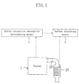
- an apparatus for purifying an exhaust gas can be constructed as shown in Figure 1 . More specifically, the apparatus includes:
- the sulfur detaching means b is operated after the sulfur component (SO x ) in the exhaust gas has been absorbed in the NO x storage material excessively.
- This embodiment makes it easy to regenerate the NO x storage material almost to the NO x absorption ability before the sulfur component is absorbed.
- the NO x absorption ability of the NO x storage materials after regeneration (which means regeneration from sulfur poisoning, which also applies to the following) is higher than that the NO x storage material comprising Ba alone, or the degree of deterioration of the NO x absorption ability when exposed to a high temperature is smaller.
- the heat resistance is higher.
- This improvement of the heat resistance is advantageous for regeneration of the NO x storage materials.
- the relationship between the improvement of the heat resistance and the regeneration of the NO x storage materials is as follows.
- the sulfur detaching means b detaches the sulfur component from the NO x storage materials not only by lowering the concentration of oxygen in the exhaust gas, but also by raising the temperature of the catalyst 25 . Therefore, for a catalyst comprising NO x storage materials having a low heat resistance, it is difficult to raise the temperature of the NO x storage materials to detach the sulfur component, which prevents achievement of the original object of the present invention.
- the sulfur detaching means b when the heat resistance of the NO x storage materials is high, the sulfur detaching means b can be effectively used for regeneration of the NO x absorption ability. In other words, deterioration of the NO x storage materials due to heat during sulfur detaching treatment can be avoided.
- the NO x absorption ability after regeneration is higher than that the NO x storage material comprising Ba alone, or the heat resistance is higher.
- the reason for this is not clear, but it seems to be as follows.
- the elements (K, Sr, Mg or La) other than Ba are more susceptible to sulfur poisoning than Ba, so that the degree of sulfur poisoning of Ba is made relatively small. Therefore, the degree of a decrease of the NO x absorption ability after sulfur poisoning is small. More specifically, Ba has higher NO x absorption ability than those of the other elements, but the presence of the other elements makes the degree of sulfur poisoning of Ba relatively small. Therefore, the degree of decrease of the NO x absorption ability is small.
- Ba is combined with the other elements (Sr, Mg or La) except K (forming a mixed oxide or a double salt, or being close or binding to each other to be nearly amorphous), which makes it difficult for sulfur poisoning to occur.
- the NO x storage material is constituted only by Ba, and the amount thereof is increased, the NO x absorption ability before sulfur poisoning and after regeneration is not significantly improved. This seems to be because when the amount of Ba exceeds a certain amount, only the particle size is increased, and the specific surface area is not increased.
- Ba is combined with the other elements (at least one selected from K, Sr, Mg and La), each is present separately because of the difference in the nature between the elements, and the specific surface area or the active site is increased. In addition, sintering due to heat hardly occurs. Furthermore, the interaction between the different elements constituting the NO x storage materials facilitate the detachment of the sulfur component.
- the combination of Ba and the other elements is advantageous to provide fine particles of the NO x storage materials.
- Sr has a significant function to make Ba and Mg particles fine.
- high dispersibility on the support of the NO x storage materials can be achieved, and heat sintering hardly occurs.
- the heat resistance of the catalyst can be high.
- the support is alumina
- Ba is reacted with the support when the catalyst reaches at a high temperature, which is likely to lead to deterioration.
- Mg serves to suppress the reaction between the support and Ba, so that the heat resistance of the catalyst can be high.
- the Ba support amount per L of the carrier is preferably about 10 to 50g, more preferably 20 to 40g.
- the support amounts of the other elements are preferably equal to or less than the support amount of Ba.
- the elements constituting the NO x storage materials include K in addition to Ba.
- K is not combined with Ba, but is highly reactive with sulfur, so that K is present around Ba and prevents Ba from sulfur-poisoned, and suppresses deterioration of the NO x absorption ability due to sulfur poisoning of Ba.
- K is more readily to detach the sulfur component than Ba, so that the NO x absorption ability after regeneration is higher.
- the elements constituting the NO x storage materials include at least one selected from Sr, Mg and La, in addition to Ba and K. This is advantageous for a high heat resistance of the NO x storage materials and prevention of heat deterioration during sulfur detachment treatment.
- Ba and Sr form a compound (a mixed oxide or a double salt) constituted by these two elements. It seems that such a Ba-Sr compound is less susceptible to sulfur poisoning than Ba alone, so that deterioration of the NO x absorption ability can be suppressed.
- Ba and Mg (at least a part of each of them) come close to each other or are combined to be nearly amorphous, although it is not crystalline.
- Such a Ba-Mg coexisting substance suppresses sulfur poisoning of Ba more than in the case of Ba alone, so that deterioration of the NO x absorption ability can be suppressed.
- K is not combined with or not be compatible with Ba, Sr or Mg, and is dispersed around the Ba-Sr compound or the Ba-Mg coexisting substance. It seems that since K is relatively highly reactive with sulfur, K prevents the Ba-Sr compound or the Ba-Mg coexisting substance from being sulfur-poisoned.
- the Ba support amount per L of the carrier is preferably 10 to 50g
- the K support amount is preferably 1g (the upper limit is 15g, for example)
- the Mg support amount is preferably 3 to 17g.
- an amount of 5 to 15g is more preferable, and an amount of 8 to 12 g is even more preferable.
- a preferable Ba support amount and a preferable K support amount per L of the carrier are the same as those in the Ba-K-Mg based catalyst.
- the Sr support amount is preferably 10 to 20g.
- 13 to 17g are more preferable. These amounts provide high heat resistance and good regeneration properties from sulfur poisoning.
- the elements constituting the NO x storage materials include Sr, in addition to Ba. This is advantageous for achievement of a high heat resistance of the NO x storage materials and prevention of heat deterioration during sulfur detachment treatment.
- the elements constituting the NO x storage materials include at least one selected from Mg and La, in addition to Ba and Sr. This is more advantageous for achievement of a high heat resistance of the NO x storage materials and prevention of heat deterioration during sulfur detachment treatment.
- the elements constituting the NO x storage materials include Mg, in addition to Ba. This is advantageous for achievement of a high heat resistance of the NO x storage materials and prevention of heat deterioration during sulfur detachment treatment.
- the elements constituting the NO x storage materials include La, in addition to Ba and Mg. This is more advantageous for achievement of a high heat resistance of the NO x storage materials and prevention of heat deterioration during sulfur detachment treatment.
- Raising the temperature of the catalyst 25 by the sulfur detaching means b can be achieved by raising the temperature of the exhaust gas.
- a temperature of the exhaust gas of 500 to 1100°C (preferably 600 to 1100°C) is preferable for detachment of sulfur from the NO x storage materials.
- a heater can be provided in the catalyst 25 and can be heated.
- Reducing the concentration of oxygen in the exhaust gas by the sulfur detaching means b can be achieved by controlling the air-fuel ratio of the engine. For example, ⁇ (oxygen-excessive ratio) of around 1 or not more than 1 achieves a concentration of oxygen in the exhaust gas of 0.5% or less, and further leads to an increase in the amount of the reduction components such as HC, CO, H 2 or the like in the exhaust gas. This is advantageous for detachment of the sulfur component from the NO x storage materials.
- the sulfur detaching means b is preferably fuel injection control means that operates a fuel injection valve in such a manner that fuel is divided into at least two portions to be injected to the combustion chamber in the cylinder during a period from the start of an air-intake stroke to the end of the compression stroke.
- fuel injection control means that operates a fuel injection valve in such a manner that fuel is divided into at least two portions to be injected to the combustion chamber in the cylinder during a period from the start of an air-intake stroke to the end of the compression stroke.
- the sulfur excessive absorption determining means that determines the excessive absorption state of the sulfur component to the NO x storage material operates in the following manner, for example: estimating an amount of absorbed SO x in the NO x storage material, based on the travel distance of the automobile and the total amount of fuel consumed during that period, or further in view of the temperature of the catalyst 25 during that period, and determining that the sulfur component reaches the excessive absorption state when the estimated value exceeds a predetermined value.
- a method for purifying an exhaust gas including NO x and a sulfur component preferably includes:
- such a method facilitates detachment of the sulfur component from the NO x storage material to recover the NO x absorption ability to a high level, when the NO x absorption ability of the NO x storage material is deteriorated by sulfur poisoning.
- this method is advantageous for purification of NO x .
- Figure 1 is a schematic diagram illustrating a structure of an apparatus for purifying an exhaust gas according to the present invention.
- Figure 2 is a schematic diagram illustrating an apparatus for purifying an exhaust gas of an embodiment of the present invention.
- Figure 3 is a graph showing the output characteristics of O 2 sensor against the change in the air-fuel ratio.
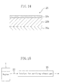
- Figure 4 is a cross-sectional view showing a schematic structure of a catalyst for purifying an exhaust gas according to the present invention.
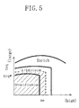
- Figure 6 is a timing chart showing the combustion injection time in each operational region.
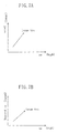
- Figure 7A is a graph showing a map where a desired torque of an engine corresponding to the number of revolutions of the engine and the opening of the accelerator is set.
- Figure 7B is a graph showing a map where the opening of a throttle valve corresponding to the number of revolutions of the engine and the desired torque is set.
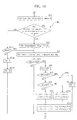
- Figure 8 is a flowchart showing the basic setting procedure for the amount and the time of fuel injection.
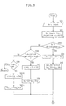
- Figure 9 is a flowchart showing a processing procedure of controlling release of NO x .
- Figure 10 is a flowchart showing a processing procedure of controlling detachment of SO x .
- Figure 11 is a flowchart showing an execution procedure of the intake stroke injection and the compression stroke injection.
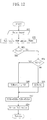
- Figure 12 is a flowchart showing a processing procedure of EGR control.
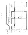
- Figure 13 is a timing chart showing changes in the air-fuel ratio at the time of controlling NO x release and SO x detachment during an engine operation.
- Figure 14 is a cross-sectional view illustrating a layer structure of a catalyst of an embodiment of the present invention.
- Figure 15 is a block diagram of an apparatus for purifying an exhaust gas from an engine using the catalyst of an embodiment of the present invention.
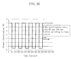
- Figure 16 is a graph showing the relationship between the time from the start of a test and the concentration of oxygen of a simulated gas contacted with the catalyst in measurement of the NO x purifying ratio.
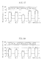
- Figure 17 is a graph showing the NO x purifying ratio for 60 seconds after switching to a lean ratio, regarding the heat resistance in Experiment 1 .
- Figure 18 is a graph showing the NO x purifying ratio for 130 seconds after switching to a lean ratio, regarding the heat resistance in Experiment 1 .
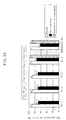
- Figure 19 is a graph showing the NO x purifying ratio for 60 seconds after switching to a lean ratio, regarding the sulfur poisoning resistance in Experiment 1 .
- Figure 20 is a graph showing the NO x purifying ratio for 130 seconds after switching to a lean ratio, regarding the sulfur poisoning resistance in Experiment 1 .
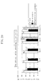
- Figure 21 is a graph showing the NO x purifying ratio for 60 seconds after switching to a lean ratio, regarding the heat resistance in Experiment 2 .
- Figure 22 is a graph showing the NO x purifying ratio for 130 seconds after switching to a lean ratio, regarding the heat resistance in Experiment 2 .
- Figure 23 is a graph showing the NO x purifying ratio for 60 seconds after switching to a lean ratio, regarding the sulfur poisoning resistance in Experiment 2 .
- Figure 24 is a graph showing the NO x purifying ratio for 130 seconds after switching to a lean ratio, regarding the sulfur poisoning resistance in Experiment 2 .
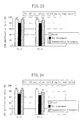
- Figure 25 is a graph showing the NO x purifying ratio for 60 seconds after switching to a lean ratio, regarding the heat resistance in Experiment 3 .
- Figure 26 is a graph showing the effects of different NO x storage materials on the NO x purifying ratio when the catalysts are fresh, after a sulfur poisoning treatment is performed, and after a regeneration treatment is performed.
- Figure 27 is a graph showing the NO x purifying ratio of the catalysts with different NO x storage materials at a gas temperature at the catalyst inlet of 350°C when the catalysts are fresh and after a heat deterioration treatment is performed.
- Figure 28 is a graph showing the NO x purifying ratio of the catalysts with different NO x storage materials at a gas temperature at the catalyst inlet of 450°C when the catalysts are fresh and after a heat deterioration treatment is performed.
- Figure 29 is a graph showing the effects of the Sr support amount on the NO x purifying ratio when the catalysts are fresh, after a sulfur poisoning treatment is performed, and after a regeneration treatment is performed, regarding a catalyst with Ba-K-Sr based-NO x storage material.
- Figure 30 is a graph showing the effects of the Sr support amount on the heat resistance of a catalyst with Ba-K-Sr based-NO x storage material.
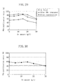
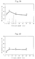
- Figure 31 is a graph showing the effects of the Mg support amount on the NO x purifying ratio when the catalysts are fresh, after a sulfur poisoning treatment is performed, and after a regeneration treatment is performed, regarding a catalyst with Ba-K-Mg based-NO x storage material.
- Figure 32 is a graph showing the effects of the Mg support amount on the heat resistance of a catalyst with Ba-K-Mg based-NO x storage material.
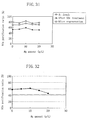
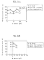
- Figure 33 is a graph showing the effects of the Sr support amount on the NO x purifying ratio, when the catalysts are fresh, after a sulfur poisoning treatment is performed, and after a regeneration treatment is performed, regarding a catalyst with Ba-K-Sr-Mg based-NO x storage material in a Mg support amount of 5g/L.
- Figure 34 is a graph showing the effects of the Sr support amount on the NO x purifying ratio, when the catalysts are fresh, after a sulfur poisoning treatment is performed, and after a regeneration treatment is performed, regarding a catalyst with Ba-K-Sr-Mg based-NO x storage material in a Mg support amount of 10g/L.
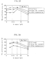
- Figure 35A is a graph showing the effects of the Sr support amount on the NO x purifying ratio, when the catalysts are fresh, after a sulfur poisoning treatment is performed, and after a regeneration treatment is performed, regarding a catalyst with Ba-K-Sr-Mg based-NO x storage material in a Mg support amount of 15g/L.
- Figure 35B is a graph showing the effects of the Mg support amount on the NO x purifying ratio, when the catalysts are fresh, after a sulfur poisoning treatment is performed, and after a regeneration treatment is performed, regarding a catalyst with Ba-K-Sr-Mg based-NO x storage material in a Sr support amount of 10g/L.
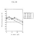
- Figure 36 is a graph showing the effects of the Mg support amount and the Sr support amount on the heat resistance of a catalyst with Ba-K-Sr-Mg based-NO x storage material.
- Figure 37 is a schematic model diagram showing a state of the catalytic layer of Ba-K-Sr-Mg based-NO x storage material.
- Figure 38 is a graph showing the effects of the K support amount on the sulfur poisoning resistance and the regeneration properties from the sulfur poisoning of the catalyst.
- Figure 39 is a graph showing the effects of the K support amount on the heat resistance of the catalyst (the NO x purifying ratio at a measurement temperature of 350°C).
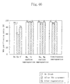
- Figure 40 is a graph showing the effects of the K support amount on the heat resistance of the catalyst (the NO x purifying ratio at a measurement temperature of 450°C).
- Figure 41 is a graph showing the relationship between the K support amount and the purifying ratio of NO x and HC.
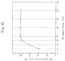
- Figure 42 is a graph showing the relationship between the Ba support amount and the purifying ratio of NO x .
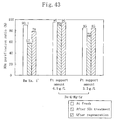
- Figure 43 is a graph showing the effects of the Pt support amount on the sulfur poisoning resistance and the regeneration properties from the sulfur poisoning of the catalyst.
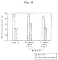
- Figure 44 is a graph showing the effects of the Pt support amount on the heat resistance of the catalyst (the NO x purifying ratio at a measurement temperature of 350°C).
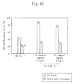
- Figure 45 is a graph showing the effects of the Pt support amount on the heat resistance of the catalyst (the NO x purifying ratio at a measurement temperature of 450°C).
- Figure 46 is a graph showing the effects of the order of impregnation of the NO x storage material on the sulfur poisoning resistance and the regeneration properties from the sulfur poisoning of the catalyst.
- Figure 47 is a graph showing the effects of the order of impregnation of the NO x storage material on the heat resistance of the catalyst.
- FIG. 2 shows the overall construction of an engine mounted with an apparatus A for purifying an exhaust gas of an embodiment of the present invention.
- a multiple cylinder engine 1 is mounted on, for example, an automobile, and a piston 3 inserted in each cylinder defines a combustion chamber 4 in the cylinder 2 .
- An ignition plug 6 connected to an ignition circuit 5 is provided on the axis center of the cylinder on the upper wall of the combustion chamber 4 in such a manner that the ignition plug 6 faces the combustion chamber 4 .
- An injector (fuel injection valve) 7 that directly injects fuel to the combustion chamber 4 is provided on the rim of the combustion chamber 4 .
- a fuel supply circuit including a high pressure fuel pump, a pressure regulator or the like is connected to the injector 7 .
- the fuel supply circuit supplies fuel to the injector 7 while regulating the pressure of the fuel from a fuel tank as appropriate, and includes a fuel pressure sensor 8 for detecting the pressure of the fuel.
- the combustion chamber 4 is in communication with an air-intake passage 10 via an air-intake port (not shown) that is opened and closed by an air-intake valve 9 .
- the air-intake passage 10 supplies drawn air that has been filtered with an air cleaner 11 to the combustion chamber 4 of the engine 1 , and includes a hot-wire airflow sensor 12 for detecting the amount of drawn air, an electric throttle-valve 13 for narrowing the air-intake passage 10 , and a surge tank 14 in this order from the upstream to the downstream.
- the electric throttle valve 13 is not mechanically coupled to an accelerator pedal (not shown), but is opened or closed by being driven by a motor 15 . Further, the throttle valve 13 is provided with a throttle opening sensor 16 for detecting the opening of the throttle-valve 13 , and the surge tank 14 is provided with an air-pressure sensor 17 for detecting the pressure of the drawn air in the surge tank 14 .
- the section of the air-intake passage 10 on the downstream side from the surge tank 14 is diverged into independent passages, each of which corresponds to each one of the cylinders 2 .
- the downstream end of each independent passage is further diverged into two passages that are in communication with the air-intake ports.
- One of the two diverged passages is provided with a swirl control valve 18 .
- the swirl control valve 18 is opened or closed by an actuator 19 .
- the swirl control valve 18 opens, the air is supplied only from the other diverged passage to the combustion chamber 4 , and strong swirl of the drawn air is generated in the combustion chamber 4 .
- the swirl control valve 4 increasingly opens, the swirl of the drawn air is weakened.
- a swirl control valve opening sensor 20 for detecting the opening of the swirl control valve 18 is provided.
- an emission passage 22 for emitting burned gas from the combustion chamber 4 is diverged at the upstream end into passages, each of which corresponds to each one of the cylinders 2 and is in communication with the combustion chamber 4 via an exhaust gas valve 23 through an exhaust gas port (not shown).
- the emission passage 22 is provided with an O 2 sensor 24 for detecting the concentration of oxygen in an exhaust gas and a catalyst 25 for purifying the exhaust gas.
- the output (electromotive force) of the O 2 sensor 24 is at a reference value E1 when the concentration of oxygen in the exhaust gas is a concentration (about 0.5%) substantially corresponding to the theoretical air-fuel ratio, as shown in Figure 3 .
- the O 2 sensor 24 is a so-called random O 2 sensor where its output is inversed stepwise at the point of the theoretical air-fuel ratio.
- the catalyst 25 is of NO x absorption and reduction type, which absorbs NO x in an atmosphere with excessive oxygen where the concentration of oxygen is high in the exhaust gas, and releases the absorbed NO x when the concentration of oxygen is decreased for reduction and purification of NO x .
- this lean NO x catalyst 25 has a carrier 25a made of cordierite of honeycomb construction, and an inner catalytic layer 25b and an outer catalytic layer 25c on the inner catalytic layer 25b are formed on the wall surface of each through-hole of the carrier 25a .
- the section of the emission passage 22 on the upstream side from the O 2 sensor 24 is connected to the upstream end of an EGR passage 26 , and the downstream end of the EGR passage 26 is connected to the air-intake passage 10 between the throttle-valve 13 and the surge tank 14 .
- An electric EGR valve 27 for regulating the opening of the passage is provided in the downstream of the EGR passage 26 so that the recirculation volume (hereinafter, referred to as EGR volume) of the exhaust gas through the EGR passage 26 can be regulated.
- the EGR passage 26 and the EGR valve 27 constitute exhaust gas recirculation mean.
- a lift sensor 28 for detecting the lift amount of the EGR valve 27 is also provided.
- the ignition circuit 5 of the ignition plug 6 , the injector 7 , the driving motor 15 of the electric throttle valve 13 , the actuator 19 of the swirl control valve 18 , the electric EGR valve 27 or the like are operated and controlled by a control unit 40 (hereinafter, referred to as ECU).
- ECU 40 a control unit 40
- output signals from the airflow sensor 12 , the throttle opening sensor 16 , the air-pressure sensor 17 , the swirl control valve opening sensor 20 , the O 2 sensor 24 and the lift sensor 28 of the EGR valve 27 are input.
- output signals from a water-temperature sensor 30 for detecting the temperature of a coolant (engine water temperature) of the engine 1, an air-temperature sensor 31 for detecting the temperature of the drawn air, an atmospheric pressure-sensor 32 for detecting the atmospheric pressure, an engine revolution number sensor 33 for detecting the number of revolutions of the engine, and an accelerator opening sensor 34 for detecting the opening of the accelerator pedal (the operation amount of the accelerator) are input to the ECU 40 .
- the form of fuel injection by the injector 7 can be switched depending on the operational state of the engine, so that the engine can be operated in different combustion states.
- a stratified combustion region a predetermined region on the side of low load and a low number of revolutions.
- fuel is collectively injected in the late stage of the compression stroke by the injector 7 .
- This is a combustion mode in which combustion occurs in a stratified state where air-fuel mixture is present in the vicinity of the ignition plug 6 .
- the regions for the other operations are designed to be homogenous combustion regions.
- fuel is injected twice by the injector 7 , namely once in the air-intake stroke and once in the compression stroke.
- the EGR valve 27 is opened so that part of the exhaust gas is allowed to flow back to the air-intake passage 10 through the EGR passage 26 .
- all the operation regions of the engine 1 are homogenous combustion regions in order to improve the combustion stability.
- the ECU 40 determines various control parameters involved in engine outputs, based on the operation state of the engine 1 .
- control parameters are the fuel injection quantity and the injection time by the injector 7 , the amount of air to be drawn that is adjusted by the throttle valve 13 , the intensity of drawn air swirl that is adjusted by the swirl control valve 18 , and the EGR amount that is adjusted by the EGR valve 27 .
- the desired torque trq of the engine 1 is calculated based on the opening of the accelerator accel and the number of engine revolutions ne .
- the desired torque trq is calculated as follows. The relationship between the opening of the accelerator accel and the number of engine revolutions ne that achieves required output performance is previously obtained by bench tests or the like. This relationship is stored in the memory of the ECU 40 as a map, and a value corresponding to the actual opening of the accelerator accel and the actual number of engine revolutions ne is read from this map.
- a desired throttle opening tvo is obtained from the previously prepared map (see Figure 7B ) based on the desired charging efficiency ce and the number of engine revolutions ne .
- the relationship between the number of engine revolutions and the throttle opening is varied depending on whether or not the EGR is provided.
- the throttle opening tvo is set to be larger when the EGR is provided than when the EGR is not provided.
- the actual charging efficiency ce of the engine 1 is calculated based on the output signals from the airflow sensor 12 , and a basic fuel injection quantity qbase is calculated based on the actual charging efficiency ce and the desired air-fuel ratio afw .
- qbase KGKF ⁇ ce/afw, where KGKF is a coefficient for calculation.
- the fuel injection time is set for each operational mode.
- the injection time Inj_TT for the compression stroke injection is obtained from the previously prepared map in accordance with the desired torque trq and the number of engine revolutions ne .
- the injection time Inj_TL for the air-intake stroke injection is obtained from the predetermined table in accordance with the number of engine revolutions ne .
- the data for the stratified combustion mode is used as the injection time Inj_TT for the compression stroke injection, and the injection time Inj_TL for the air-intake stroke injection is obtained from the previously prepared map in accordance with the desired air-fuel ratio afw and the number of engine revolutions ne .
- the ignition time of the engine 1 is set for each operational mode.
- the basic ignition time is obtained based primarily on the desired torque trq and the number of engine revolutions ne .
- the basic ignition time is obtained based on the charging efficiency ce and the number of engine revolutions ne .
- This basic ignition time is corrected based on the engine water temperature.
- the swirl control valve 18 is controlled for each operational mode. In the stratified combustion mode, the opening of the swirl control valve 18 is controlled to be larger, as the desired torque trq is larger, or the number of engine revolutions ne is larger.
- the opening of the swirl control valve 18 is controlled to be smaller, as the desired torque trq is larger, or the number of engine revolutions ne is larger. Also the EGR amount is controlled for each operational mode, depending on the operational state of the engine 1, which will more specifically be described later.
- the engine 1 is in the low load region and the stratified combustion state to significantly improve the fuel efficiency, and a so-called lean NO x catalyst 25 of absorption and reduction type is adopted so that NO x in the exhaust gas can be reduced even if the air-fuel ratio is very lean, such as in the stratified combustion state.
- a so-called lean NO x catalyst 25 of absorption and reduction type is adopted so that NO x in the exhaust gas can be reduced even if the air-fuel ratio is very lean, such as in the stratified combustion state.
- the NO x is released for reduction and purification.
- a slight amount of SO x contained in the exhaust gas is gradually absorbed by a NO x storage material, and the amount of absorbed SO x in the catalyst 25 is gradually increased over time to a point where the increased SO x interferes with the NO x purifying performance. At this point, the SO x is forcefully detached from the catalyst 25 .
- the inner catalytic layer 25b of the lean NO x catalyst 25 includes a porous support, and a catalytic metal and a NO x storage material that are supported by the support.
- Pt can be used as the catalytic metal.
- Ba and at least one selected from the group consisting of K, Sr, Mg and La can be used as the NO x storage material.
- Alumina and a Ce-Zr-Sr mixed oxide of (or a Ce-Zr mixed oxide) can be used as the support.
- the outer catalytic layer 25c includes a porous support, and a catalytic metal and a NO x storage material that are supported by the support.
- Pt and Rh can be used as the catalytic metal.
- Ba and at least one selected from the group consisting of K, Sr, Mg and La can be used as the NO x storage material.
- Zeolite can be used as the support.
- the support of the outer catalytic layer 25c alumina and a Ce-Zr-Sr mixed oxide (or a Ce-Zr mixed oxide) can be used as well.
- the catalytic layer 25 can be one layer coating type, where a layer of support is formed on the surface of the wall of the carrier, and a catalytic metal and a NO x storage material are supported by the support.
- the regeneration of the catalyst 25 by detachment of NO x and SO x is performed when it is determined that the absorption of sulfur components by the NO x storage material reaches the excessive absorption state.
- This can be achieved in the following manner.
- the air-fuel ratio in the combustion chamber 4 is controlled to be in the vicinity of the approximate theoretical air-fuel ratio, while the injection of fuel by the injector 7 is divided into two operations.
- the temperature of the exhaust gas is increased, and the temperature of the NO x storage material is increased.
- the CO concentration in the exhaust gas can be increased significantly.
- the air-fuel ratio is switched between the lean side and the rich side alternately so that the CO concentration and the HC concentration in the exhaust gas can be changed periodically.
- step SA1 after the start, various kind of sensor signals such as those from the airflow sensor 12 , the O 2 sensor 24 , the water-temperature sensor 30 , the engine revolution number sensor 33 , and the accelerator opening sensor 34 are received, and various kinds of data are input from the memory of the ECU 40 .
- step SA2 the basic fuel injection quantity qbase is calculated and set based on the charging efficiency ce and the desired air-fuel ratio afw .
- step SA6 when the result of the determination is NO in step SA6 , that is, the operation is not in the stratified combustion mode, the procedure goes to SA9 , where it is determined whether or not to perform fuel cut control.
- step SB1 shown in Figure 9 the amount of absorbed NO x in the catalyst 25 is estimated. This estimation is performed based on, for example the travel distance from the point where the last instruction to release NO x (NO x release control) is issued and the total amount of the fuel consumed during that period. Based on the results of the estimation, in the following step SB2 , it is determined whether or not the amount of absorbed NO x is equal to or more than a predetermined value that has been previously set, namely, whether or not the amount of absorbed NO x is excessive.
- the result may be YES regardless of the amount of absorbed NO x , and the NO x release control, which will be described below, can be performed.
- step SB4 the first timer value T1 whose initial value is 0 is incremented, and in the following step SB5 , it is determined whether or not the first timer value T1 is equal to or more than the threshold T10 that has been previously set (approximately 2 to 10 seconds).
- the procedure goes to step SB6 , each step of steps SB6 to SB9 , feedback control calculation is performed based on the signals from the O 2 sensor 24 .
- step SB6 an output E from the O 2 sensor 24 is compared with a reference value E1 that corresponds to the theoretical air-fuel ratio.
- the procedure goes to SB7 , where feedback corrected values ⁇ CL and ⁇ CT as current values are calculated by subtracting constants ⁇ and ⁇ , respectively, from the previous values.
- the procedure goes to SB8 , where feedback corrected values ⁇ CL and ⁇ CT as current values are calculated by adding constants ⁇ and ⁇ , respectively, to the previous values.
- step SB9 the injection pulse widths ⁇ L and ⁇ T in the air-intake stroke and the compression stroke during NO x release control are calculated based on the injection pulse width ⁇ L4 and ⁇ T4 obtained in accordance with the actual charging efficiency ce to achieve the theoretical air-fuel ratio in the combustion chamber 4 and the feedback corrected values ⁇ CL and ⁇ CT obtained in steps SB7 and SB8 , and the injection times thereof are set again.
- ⁇ L ⁇ L4 + ⁇ CL
- Inj_TL Inj_TL4
- ⁇ T ⁇ T4 + ⁇ CT
- Inj_TT Inj_TT4
- the fuel injection quantities in the air-intake and the compression processes are gradually decreased by constant quantities a and ⁇ for each control cycle so that the air-fuel ratio is changed to be lean.
- the fuel injection quantities are gradually increased so that the air-fuel ratio is changed to be rich.
- the injection quantities both in the air-intake and the compression processes are feedback-corrected.
- only the injection quantity in the air-intake stroke can be feedback-corrected. This is because a change in the fuel injection quantity in the air-intake stroke hardly gives an adverse effect on the combustion state or exhaust gases.
- step SB2 when the result of the determination is NO, the procedure goes to step SB10 , where the status of the flag F1 is determined.
- step SC1 shown in Figure 10 the degree of sulfur poisoning of the catalyst 25 , namely, the amount of absorbed SO x is estimated. Similarly to the estimation of the amount of absorbed NO x in step SB1 , this estimation is performed based on the travel distance from the point where the last instruction to detach SO x (SO x detachment control) is issued and the total amount of the fuel consumed during that period, in view of the temperature of the catalyst during that period.
- step SC2 it is determined whether or not the amount of absorbed SO x is equal to or more than a predetermined value that has been previously set, namely, whether or not the amount of absorbed SO x is excessive.
- the sulfur component is contained in the exhaust gas in a slight amount, so that the travel distance until the amount of absorbed SO x becomes excessive is far longer than that until the amount of absorbed NO x becomes excessive.
- step SC4 the temperature of the exhaust gas thg , namely, the temperature of the catalyst 25 , is estimated. This estimation is performed primarily based on the actual charging efficiency ce and the engine revolution number ne , in view of the period of time for operation in the stratified combustion mode within a predetermined time before the estimation, and the time at which divided injection was performed. The temperature of the exhaust gas thg tends to be higher as the charging efficiency or the engine revolution number is higher, and tends to be made high by divided injection. On the other hand, in the stratified combustion mode, the temperature of the exhaust gas thg is significantly low, so that the temperature of the catalyst 25 becomes lower, as the period of time for operation in the stratified combustion mode is longer.
- step SC5 it is determined whether or not the temperature of the exhaust gas thg is equal to or higher than the preset temperature thg0 (e.g., 450°C).
- the procedure goes to step SD1 of Figure 11 .
- the procedure goes to step SC6 , where the SO x detachment control is performed. In this manner, only when the temperature of the exhaust gas is high to some extent, the SO x detachment control is performed, because the detachment properties of SO x are not satisfactory without the temperature of the catalyst 25 being high to some extent.
- step SC6 the second timer value T2 whose initial value is 0 is incremented, and in step SC7 , it is determined whether or not the second timer value T2 is equal to or more than the threshold T20 that has been previously set (approximately 1 to 10 minutes).
- the procedure goes to steps SC8 and SC11 and feedback control calculation is performed based on the signals from the O 2 sensor 24 .
- the specific procedure of the feedback control calculation is the same as that of steps SB6 to SB9 of Figure 9 , and therefore description thereof will be omitted.
- step SC2 when the result of the determination in step SC2 is NO, the procedure goes to step SC13 and the status of the flag F2 is determined.
- the procedure goes to step SC4 .
- step SD1 it is determined whether or not the air-intake stroke injection pulse width ⁇ L is zero.
- the procedure goes to step SD4 .
- step SD2 it is determined whether or not the timing for the air-intake stroke injection time Inj_TL has come.
- the injection timing is awaited.
- step SD3 the air-intake stroke injection is performed.
- step SD6 the compression stroke injection is performed in the same manner as above, and then a return is performed.
- steps SC1 and SC2 of the flow shown in Figure 10 constitute sulfur excessive absorption determining means 40a for determining that the amount of absorbed SO x in the catalyst 25 is equal to or more than a predetermined amount. Furthermore, steps SC8 to SC11 constitute sulfur detaching means 40b for detaching SO x from the NO x storage material of the catalyst 25
- the sulfur detaching means 40b controls the air-fuel ratio to be in the vicinity of the theoretical air-fuel ratio so that the oxygen concentration in the exhaust gas is reduced. In addition, the sulfur detaching means 40b periodically changes the air-fuel ratio alternately between the rich side and the lean side from the theoretical air-fuel. On the other hand, the sulfur detaching means 40b keeps the temperature of the catalyst 25 high and significantly increases the CO concentration in the exhaust gas by allowing the injector 7 to inject fuel twice, that is, once in the air-intake stroke and once in the compression stroke of the cylinder. In addition, the CO concentration is increased by correcting the fuel injection quantity to be increased.
- step SE1 after the start, various kind of sensor signals such as those from the airflow sensor 12 and the engine revolution number sensor 33 are received, and various kinds of data are input from the memory of the ECU 40 .
- step SE2 the desired EGR ratio is calculated based on the actual charging efficiency ce and the engine revolution number ne .
- An EGR amount that achieves the desired EGR ratio is set as a basic EGR amount EGRb .
- the desired EGR ratio is calculated as follows. The relationship between the charging efficiency ce and the number of engine revolutions ne is previously obtained by bench tests or the like. This relationship is stored in the memory of the ECU 40 as a map.
- step SE3 based on the value of the first flag F1 , it is determined whether or not the NO x release control should be performed.
- step SE5 based on the value of the first flag F1 .
- step SE4 based on the value of the second flag F2 .
- step SE5 based on the value of the second flag F2 , it is determined whether or not the SO x detachment control should be performed.
- step SE5 a correction value EGRc for correcting the EGR amount either to be increased or decreased is designated as a predetermined value ⁇ ( ⁇ ⁇ 0).
- step SE7 the basic EGR amount EGRb and the correction value EGRc are added, so that the final EGR amount EGRt is calculated.
- step SE8 a control signal is output to the EGR valve 27 to drive the EGR valve 27 so that the opening corresponds to the final EGR amount EGRt . Then, a return is performed.
- the opening of the EGR valve 27 is corrected so that the EGR amount is slightly small while the air-fuel ratio in the combustion chamber 4 is kept in the vicinity of the theoretical air-fuel ratio, by performing at least one of the NO x release control and the SO x detachment control and by feedback-controlling the fuel injection amount by the injector 7 , as described above.
- NO x absorbed in the catalyst 25 is released for reduction and purification.
- NO x release control is performed as shown in the flow of Figure 9 .
- the absorption ability of NO x may be deteriorated because SO x is gradually accumulated in the catalyst 25 during operation of the engine 1 .
- the sulfur excessive absorption determining means of the engine 1 determines that the amount of absorbed SO x is excessive, so that the flag F2 is turned to ON (see Figure 13 ).
- the catalyst 25 has a high temperature (for example, 450°C or more), SO x release control is performed.
- Both the NO x release and the SO x release are performed with division of the fuel injection into two operations and feedback control of the air-fuel ratio to be in the vicinity of the air-fuel theoretical ratio.
- the oxygen concentration in the exhaust gas is decreased, and the CO concentration and the HC concentration in the exhaust gas are significantly increased and changed periodically. Further, the temperature of the exhaust gas is increased. Therefore, detachment of NO x and SO x from the catalyst 25 is facilitated.
- the fuel is divided for two operations of injection by the injector 7 , so that a part of the fuel injected in the air-intake stroke of each cylinder 2 is diffused uniformly in the combustion chamber 4 to form a lean air-fuel mixture.
- the remaining fuel injected in the compression stroke forms an excessively rich air-fuel mixture in the vicinity of the ignition plug 6 .
- this excessively rich air-fuel mixture portion has a high initial combustion speed immediately after ignition, oxygen is insufficient. Therefore, CO is generated readily because of local incomplete combustion.
- combustion in the surrounding lean air-fuel mixture portion becomes mild, and a part of the fuel is released without being burned completely. As a result, the temperature of the exhaust gas is increased by afterburning and CO is generated more readily.
- the ratio of fuel droplets having rough particles that is injected in the early time in the opening is increased, resulting in easy generation of CO.
- the fuel injection quantity by the injector 7 is increased, and the air-fuel ratio in the combustion chamber 4 is controlled to be substantially the theoretical air-fuel ratio, so that the concentrations of the reductant components such as CO and HC in the exhaust gas are increased.
- the fuel injection quantity is feedback-corrected based on signals from the O 2 sensor 24 , so that the air-fuel ratio is periodically changed alternately between the rich side and the lean side. Therefore, the concentrations of CO, HC and the like in the exhaust gas are changed periodically.
- the actions of NO x and SO x adsorbed onto the catalyst 25 on CO, HC and the like are increased, so that the release of NO x and SO x from the catalyst 25 is facilitated.
- the period of time required for sufficient detachment of SO x from the catalyst 25 namely, the period of time during which the air-fuel ratio is controlled to be substantially the theoretical air-fuel ratio only for this purpose can be shortened. Therefore, sufficient regeneration of the catalyst 25 and stable performance for NO x removal can be achieved with minimal deterioration of the fuel cost.
- NO x and HC in the exhaust gas is activated by a precious metal supported by zeolite of the outer catalytic layer 25c , so that NO is converted to NO 2 , and partial oxidation or cracking occurs in HC, which leads to a highly reactive state in terms of energy. For this reason, NO 2 converted from NO by the outer catalytic layer 25c is more easily absorbed by the NO x storage material of Ba or other elements, so that its NO x absorption ratio is increased.
- NO x is adsorbed onto the surface of the NO x storage material (e.g., Ba particles) in the form of nitrate. It seems that the nitric acid radical of the nitrate is substituted by supply of CO so that carbonate and nitrogen dioxide are generated.
- the reaction with Ba particles is as follows. Ba(NO 3 ) 2 + CO ⁇ BaCO 3 + NO 2 ⁇ (coefficients omitted)
- nitrogen dioxide is reacted with HC, CO etc. on the catalytic metal for reduction and purification.
- NO 2 + HC + CO ⁇ N 2 + H 2 O + CO 2 coefficients omitted
- the catalyst can absorb NO x in the exhaust gas sufficiently again (regeneration of the catalyst).
- the catalyst 25 CO and HC in the exhaust gas are adsorbed and retained in zeolite of the outer catalytic layer 25c , so that the released NO x can be reduced and purified reliably, as described above.
- the amount of NO x released from the catalyst 25 becomes small, CO or HC is not emitted to the air. Therefore, most of the NO x absorbed in the catalyst 25 can be released. In other words, the catalyst 25 can be regenerated sufficiently.
- the outer catalytic layer 25c supports Pt and Rh, NO 2 can be reduced and degraded effectively at a relatively low temperature (e.g., 200 to 250°C). This is especially advantageous when the engine 1 is operated in the stratified combustion state, as in this embodiment. In such stratified combustion, the air-fuel ratio is very lean, and the temperature of the exhaust gas is very low.
- the catalyst 25 SO x is adsorbed onto the surface of the NO x storage material (e.g., Ba particles) in the form of sulfate, as in the case of NO x . It seems that the sulfuric acid radical of the sulfate is substituted by supply of CO so that carbonate and sulfur dioxide are generated.
- the reaction with Ba particles is as follows. BaSO 4 + CO ⁇ BaCO 3 + SO 2 ⁇ (coefficients omitted)
- zeolite is supported by the outer catalytic layer 25c of the catalyst 25 , and zeolite causes partial oxidation of HC in the exhaust gas so that HC is converted to HCO or CO. Therefore, the CO concentration that affects SO x adsorbed onto the surface of the NO x storage material of the inner catalytic layer 25b is further increased.
- FIG 14 shows the catalyst 25 for purifying the exhaust gas.
- the catalyst 25 is a laminate comprising a monolith carrier 25a , an inner catalytic layer 25b , and an outer catalytic layer 25c .
- the monolith carrier 25a is made of for example, cordierite, which is a carrier material having an excellent heat resistance.
- the inner catalytic layer 25b is formed near the surface of the carrier 25a
- the outer catalytic layer 25c is formed away from the surface of the carrier 25a .
- the inner catalytic layer 25b includes a first precious metal component (e.g., Pt), Ba, K, Sr and Mg as NO x storage materials, a first support supporting the first precious metal and the NO x storage materials, and a binder for binding the support powder for retention in the carrier.
- the first support is formed of a mixture of alumina and a CeO 2 ⁇ ZrO 2 ⁇ SrO mixed oxide.
- the outer catalytic layer 25c includes a second precious metal component (e.g., Pt, Rh), Ba, K, Sr and Mg as NO x storage materials, a second support supporting the precious metal and the NO x storage materials, and a binder for binding the second support powder for retention in the carrier.
- the second support is formed of zeolite.
- the content of impurities in each of the catalytic layers 25b and 25c is 1% or less.
- the basic method for producing the catalyst 25 is as follows.
- the first support (a mixture of alumina and a CeO 2 ⁇ ZrO 2 ⁇ SrO mixed oxide), the binder, and water are mixed to form slurry.
- the monolith carrier is wash-coated with this slurry and dried and calcined, so that an inner coating layer is formed.
- the second precious metal is supported by the second support (zeolite) by evaporation to dryness so that catalyst power is formed.
- the catalyst power, the binder and water are mixed to form slurry.
- the monolith carrier provided with the inner coating layer is wash-coatedwith this slurry and dried and calcined, so that an outer coating layer is formed on the inner coating layer.
- a solution of the first precious metal component, and solutions of Ba component, K component, Sr component and Mg component are mixed to prepare a mixed solution.
- the inner coating layer and the outer coating layer are impregnated with the mixed solution at the same time, and are dried and calcined.
- the inner catalytic layer and the outer catalytic layer are formed as the inner coating layer and the outer coating layer, respectively.
- the catalyst 25 is provided in the emission passage 22 for emitting an exhaust gas from the lean combustion engine 4 for automobiles.
- the provision site corresponds to a site immediate downstream of an emission manifold.
- the catalyst 25 stores NO x contained in the exhaust gas in Ba, K, Sr and Mg during lean combustion operation. Then, during operation of combustion at the theoretical air-fuel ratio or rich combustion operation ( ⁇ ⁇ 1), in the catalyst 25 , NO x released from Ba or the like is reacted with HC, CO and H 2 to purify the exhaust gas as well as the ternary catalyst.
- the catalyst 25 has a lean NO x purification function, and the concentration of oxygen in the exhaust gas during lean combustion operation is for example, 4 or 5% to 20%, and the air-fuel ratio A/F is 18 to 150. On the other hand, the concentration of oxygen during rich combustion operation is 0.5% or less.
- the catalyst 25 has a lean NO x purification function
- the amount of stored NO x of the catalyst 25 is saturated so that the NO x purification performance is deteriorated. Therefore, control is performed so that a cycle as follows is repeated.
- a lean combustion operation is performed for 2 to 3 minutes, during which NO x is stored in the NO x storage material. Then, a rich combustion operation is performed for 1 to 5 seconds, during which the stored NO x is released for purification.
- the air-fuel ratio in the combustion chamber is made rich, and ignition retard control for delaying an ignition time is performed for 2 to 10 minutes.
- the temperature of the exhaust gas is raised, so that the temperature of the NO x storage materials is also increased.
- the sulfur component is detached from the sulfur-poisoned NO x storage materials for regeneration.
- the outer catalytic layer 25c HC that has been stored in zeolite when the catalyst has a low temperature is released with increasing the temperature of the catalyst, and HC is reacted with NO in the exhaust gas without being partially oxidized, or HC is reacted with NO after being partially oxidized and thus NO x is purified.
- NO 2 generated by oxidation of NO in the outer catalytic layer 25c is stored in the NO x storage materials, and apparently NO x is purified.
- the outer catalytic layer 25c exerts a function as a catalyst for selective reduction NO x purification
- the inner catalytic layer 25b exerts a function as a catalyst for lean NO x purification.
- the catalyst 25 is a lean NO x catalyst, but is not limited thereto and can be a ternary catalyst comprising a Ce-Zr-Sr mixed oxide as an oxygen storage material.
- the mixed oxide can act effectively as an oxygen supply source for HC oxidation, so that HC can be oxidized and eliminated. As a result, a high HC purification performance can be obtained.
- the catalyst 25 is used to purify an exhaust gas of a gasoline engine, but is not limited thereto and can be used to purify an exhaust gas of a diesel engine having an air-fuel ratio A/F of 18 to 50.
- injection retard control for delaying the fuel injection time is performed to raise the temperature of the exhaust gas.
- a catalyst of Example 1 was prepared in the following manner. Formation of an inner coating layer
- ⁇ -alumina, CeO 2 ⁇ ZrO 2 ⁇ Sm 2 O 3 as a mixed oxide (a mass composition ratio of CeO 2 :ZrO 2 :Sm 2 O 3 of 23:73:4)and an alumina binder were weighed and mixed so that the support amount of ⁇ -alumina was 150g/L and the support amount of the mixed oxide was 150g/L, and the support amount of the alumina binder was 30g/L.
- the support amount refers to an amount of dry mass per L of a carrier when the substance is supported in the honeycomb carrier that is described later. Then, ion exchanged water was added thereto to prepare slurry.
- a monolith carrier made of cordierite was immersed in this slurry and lifted up, and excess slurry was blown off. In this manner, the carrier was wash-coated with the slurry. Then, this was dried at a temperature of 150°C for one hour, and calcined at a temperature of 540°C for two hours to form an inner coating layer.
- the conditions of drying and calcining are the same as those described below.
- the Pt-Rh/MFI catalyst powder and the alumina binder were weighed and mixed so that the support amount of the catalyst power was 20g/L and the support amount of the binder was 4g/L, and an ion exchanged water was added to the mixture, so that a slurry was prepared.
- the carrier provided with the inner coating layer was wash-coated with the slurry, and then dried and calcined to form an outer coating layer.
- aqueous solution of dinitrodiamine platinum nitrate, an aqueous solution of barium acetate, an aqueous solutionof potassium acetate, an aqueous solution of strontium acetate, and an aqueous solution of magnesium acetate were weighed and mixed so that the Pt support amount was 3g/L, the Ba support amount was 30g/L, the K support amount was 6g/L, the Sr support amount was 10g/L, and the Mg support amount was 10g/L to prepare a mixed solution.
- the inner coating layer and the outer coating layer of the carrier were impregnated with the mixed solution, and were dried and calcined.
- the content of impurities in the obtained catalyst was less than 1%. This also applies to other examples of catalysts described below.
- a catalyst of Example 2 was prepared by the same method and under the same conditions as in Example 1 except that CeO 2 ⁇ ZrO 2 ⁇ La 2 O 3 (a mass composition ratio of CeO 2 :ZrO 2 :La 2 O 3 of 23:73:4) was used as a mixed oxide for the inner coating layer.
- a catalyst of Example 3 was prepared by the same method and under the same conditions as in Example 1 except that CeO 2 ⁇ ZrO 2 ⁇ In 2 O 3 (a mass composition ratio of CeO 2 :ZrO 2 :In 2 O 3 of 23:73:4) was used as a mixed oxide for the inner coating layer.
- a catalyst of Example 4 was prepared by the same method and under the same conditions as in Example 1 except that CeO 2 ⁇ ZrO 2 ⁇ SrO (a mass composition ratio of CeO 2 :ZrO 2 :SrO of 23:73:4) was used as a mixed oxide for the inner coating layer.
- a catalyst for reference was prepared by the same method and under the same conditions as in Example 1 except that CeO 2 ZrO 2 (a mass composition ratio of CeO 2 :ZrO 2 of 75:25) was used as a mixed oxide for the inner coating layer.
- the catalysts of Examples 1 to 4 and Reference Example were heated in an ambient atmosphere at 900°C for 24 hours.
- the catalyst was attached to a fixed floor flow-through reaction evaluation apparatus, and as shown in Figure 16 , a simulated exhaust gas (gas composition A) at a lean air-fuel ratio was allowed to flow for 60 seconds, and then the gas composition was switched and a simulated exhaust gas having a rich air-fuel ratio (gas composition B ) was allowed to flow for 60 seconds. These operations constitute one cycle, and this cycle was repeated 5 times. Then, the gas composition was switched to that at the lean air-fuel ratio (gas composition A ), and for 60 seconds and 130 seconds from this point of switching (600 seconds later from the test start), the NO x purification ratio (lean NO x purification ratio) was measured. The temperature of the catalyst and the temperature of the simulated exhaust gas were 350°C.
- the gas composition was shown in Table 2 .
- the space velocity SV was 25000h -1 .
- Gas composition A Gas composition B Lean Rich HC(C 3 H 6 ) 4000ppm 4000ppm NO 260ppm 260ppm CO 0.16% 0.16% CO 2 9.75% 9.75% H 2 650ppm 650ppm O 2 7% 0.5% N 2 the remaining the remaining the remaining the remaining gas
- Figures 17 and 18 show the NO x purification ratios for 60 seconds and 130 seconds after the switching point.
- Example 4 where a CeO 2 ⁇ ZrO 2 ⁇ SrO mixed oxide was used has a higher NO x purification ratio than those of Examples 1 to 3 , and thus has excellent heat resistance.
- Table 1 although Examples 2 and 4 have substantially equal specific surface areas and oxygen storage abilities, Example 4 exhibited a better NO x purification ratio. This may be because Sr highly activates oxygen that comes in and out the mixed oxide so that the activity thereof is not lost even after the mixed oxide is exposed to a high temperature atmosphere for a long time.
- the mixed oxide of Example 3 has large oxygen storage ability, the NO x purification ratio thereof was small. This seems to be because the active area as an oxygen storage material was small.
- Example 4 For each catalyst of Examples 1 to 4 and Reference Example, a fresh catalyst that has not been subjected to a deterioration treatment, and a catalyst that has been subjected to a SO 2 treatment (sulfur poisoning deterioration treatment) that is described below were prepared.
- SO 2 treatment sulfur poisoning deterioration treatment
- Example 4 and Reference Example a catalyst that has been subjected to a regeneration treatment that is described below after the SO 2 treatment was prepared as well.
- a SO 2 treatment was performed in the following manner.
- a simulated exhaust gas constituted by 50ppm of SO 2 and 20% of O 2 and N 2 was passed through the catalyst attached to a fixed floor flow-through reaction evaluation apparatus for 60 minutes.
- the temperature of the catalyst at the inlet was 350°C.
- the space velocity SV was 55000h -1 .
- a regeneration treatment was performed in the following manner.
- the temperature of the catalyst at the inlet was 600°C.
- the space velocity SV was 120000h -1 .
- Figures 19 and 20 show the NO x purification ratios for 60 seconds and 130 seconds after the switching point.
- Examples 1 to 4 have higher NO x purification ratios than that of Reference Example, and thus have more excellent sulfur poisoning resistance.
- the reason for this is not clear, but it seems that the presence of Sm, La, In or Sr provides fine NO x storage materials so that the surface areas thereof were large, and therefore the catalysts were less susceptible to sulfur poisoning. Consequently, sulfur poisoning deterioration of the NO x storage materials can be suppressed by contacting the exhaust gas containing the sulfur component with the lean NO x purifying catalyst containing Sm, La, In or Sr.
- Example 4 Furthermore, regeneration of the NO x purification performance can be confirmed in Example 4 and Reference Example to which the regeneration treatment was performed. Especially, Example 4 exhibits a very high regeneration performance. Therefore, it is preferable to raise the temperature of the catalyst when it is determined that the lean NO x purifying catalyst containing Sm, La, In or Sr was sulfur-poisoned. This seems to realize high regeneration ability from sulfur poisoning of the catalyst.
- a catalyst of Example 5 was prepared in the following manner. Formation of an inner coating layer
- ⁇ -alumina, a Ce-Zr-Sr mixed oxide (a CeO 2 ⁇ ZrO 2 ⁇ SrO mixed oxide, a mass composition ratio of CeO 2 :ZrO 2 :SrO of 73.3:25.7:1) and an alumina binder were weighed and mixed so that the support amount of ⁇ -alumina was 160g/L, the support amount of the Ce-Zr-Sr mixed oxide was 160g/L, and the support amount of the binder was 30g/L. Then, ion exchanged water was added thereto to prepare slurry.
- a honeycomb carrier was wash-coated with a half amount of the slurry, and dried and calcined to form an inner coating layer. Then, the inner coating layer was wash-coated with the other half of the amount of the slurry, and dried and calcined in the same manner to form an outer coating layer.
- Aqueous solutions of dinitrodiamine platinum nitrate, rhodium nitrate, barium acetate, potassium acetate, strontium acetate, and magnesium acetate were weighed and mixed so that the Pt support amount was 3.5g/L, the Rh support amount was 0.1g/L, the Ba support amount was 30g/L, the K support amount was 6g/L, the Sr support amount was 10g/L, and the Mg support amount was 10g/L to prepare a mixed solution. Then, the inner coating layer and the outer coating layer of the carrier were impregnated with the mixed solution, and were dried and calcined.
- a catalyst of Example 6 was prepared by the same method and under the same conditions as in Example 5 except that a Ce-Zr mixed oxide (a CeO 2 ⁇ ZrO 2 mixed oxide, a mass composition ratio of CeO 2 :ZrO 2 of 74:26) was used as a mixed oxide.
- a Ce-Zr mixed oxide a CeO 2 ⁇ ZrO 2 mixed oxide, a mass composition ratio of CeO 2 :ZrO 2 of 74:26
- Example 5 The catalysts of Examples 5 and 6 were heated in an ambient atmosphere at 900°C for 24 hours. Thereafter, NO x purification ratios (lean NO x purification ratios) were measured for 60 seconds and 130 seconds from the point at which the gas composition was switched to a lean air-fuel ratio (gas composition A).
- Figure 21 shows the NO x purification ratios measured for 60 seconds from the point of switching to a lean air-fuel ratio
- Figure 22 shows the NO x purification ratios measured for 130 seconds from the point of switching to a lean air-fuel ratio.
- Figures 21 and 22 show that Example 5 where the mixed oxide contains Sr has a higher NO x purification ratio than that of Example 6 that contains no Sr, although Example 5 has a slightly smaller amount of CeO 2 than that of Example 6 . This indicates that using a Ce-Zr-Sr double compound has an effect on improving the heat resistance of the catalyst.
- Example 5 where the mixed oxide contains Sr has substantially no difference from Example 6 that contains no Sr in the fresh catalyst.
- Example 5 has higher NO x purification ratios after the SO 2 treatment and the regeneration treatment.
- Example 7 A catalyst of Example 7 was prepared and the NO x purification ratio for 60 seconds after switching to a lean air-fuel ratio was measured by the test of Evaluation 1 and was compared with the test results of Examples 5 and 6 . Thus, the effect of the ratio of SrO in the mixed oxide on the NO x purification ratio was investigated.
- a catalyst of Example 7 was prepared by the same method and under the same conditions as in Example 5 except that a Ce-Zr-Sr mixed oxide (a CeO 2 ⁇ ZrO 2 ⁇ SrO mixed oxide, a mass composition ratio of CeO 2 :ZrO 2 :SrO of 71:25:4) was used as a mixed oxide.
- a Ce-Zr-Sr mixed oxide a CeO 2 ⁇ ZrO 2 ⁇ SrO mixed oxide, a mass composition ratio of CeO 2 :ZrO 2 :SrO of 71:25:4
- Figure 25 shows the results. According to Figure 25 , Example 7 that has a larger SrO ratio in the mixed oxide has a slightly lower NO x purification ratio for 60 seconds after switching to a lean ratio than that of Example 6 that contains no Sr in the mixed oxide. Therefore, the results indicate that the smaller ratios of SrO in the mixed oxide are better. Preferable ratios are 0.5 to 2.0 mass percent.
- Catalysts of Examples 1 ' to 11 ' were prepared in the following manner, and the effects of the type of the NO x storage materials on the NO x purification ratio, the sulfur poisoning resistance and the regeneration properties from sulfur poisoning were investigated.
- the support amount refers to an amount of dry mass per L of a carrier when the substance is supported in the honeycomb carrier, and the same applies to the following examples.
- the amount of the combination of Pt and Rh in the catalyst power was about 2.5 wt%.
- Aqueous solutions of dinitrodiamine platinum nitrate and barium acetate were weighed and mixed so that the Pt support amount was 6.0g/L and the Ba support amount was 30g/L to prepare a mixed solution.
- ⁇ -alumina, a CeO 2 ⁇ ZrO 2 mixed oxide and an alumina binder were weighed and mixed so that the support amount of ⁇ -alumina was 150g/L, the support amount of the mixed oxide was 150g/L, and the support amount of the binder was 30g/L. Then, ion exchanged water was added thereto to prepare slurry.
- a honeycomb carrier (a volume of 25mL, a mass per L of the carrier of 420g/L) made of cordierite was immersed in this slurry and lifted up, and excess slurry was blown off. In this manner, the carrier was wash-coated with the slurry. Then, this was dried and calcined to form an inner coating layer.
- the Pt-Rh/MFI catalyst powder and the alumina binder were weighed and mixed so that the support amount of the catalyst power was 20g/L, and the support amount of the binder was 4g/L, and an ion exchanged water was added thereto to prepare a slurry.
- the carrier provided with the inner coating layer was wash-coated with the slurry, and then dried and calcined to form an outer coating layer.
- the inner coating layer and the outer coating layer of the carrier were impregnated with the mixed solution, and were dried and calcined.
- the total Pt support amount is 6.5g/L.
- the content of impurities in the obtained catalyst was less than 1%. This also applies to other examples of catalysts described below.
- the catalyst was prepared by the same method and under the same conditions as in Example 1' , except that aqueous solutions of dinitrodiamine platinum nitrate and barium acetate were weighed and mixed so that the Pt support amount was 6.0g/L and the Ba support amount was 50g/L to prepare a mixed solution.
- Pt is supported in an amount of 0.5g/L by the Pt-Rh/MFI catalyst powder of the outer coating layer and in an amount of 6.0g/L by the mixed solution. Therefore, the total Pt support amount is 6.5g/L.
- the catalyst was prepared by the same method and under the same conditions as in Example 1', except that aqueous solutions of dinitrodiamine platinum nitrate, barium acetate, strontium acetate, and lanthanum acetate were weighed and mixed so that the Pt support amount was 6.0g/L, the Ba support amount was 30g/L, the Sr support amount was 10g/L, and the La support amount was 10g/L to prepare a mixed solution.
- Pt is supported in an amount of 0.5g/L by the Pt-Rh/MFI catalyst powder of the outer coating layer and in an amount of 6.0g/L by the mixed solution. Therefore, the total Pt support amount is 6.5g/L.
- the catalyst was prepared by the same method and under the same conditions as in Example 1', except that aqueous solutions of dinitrodiamine platinum nitrate, barium acetate, magnesium acetate, and lanthanum acetate were weighed and mixed so that the Pt support amount was 6.0g/L, the Ba support amount was 30g/L, the Mg support amount was 10g/L, and the La support amount was 10g/L to prepare a mixed solution.
- Pt is supported in an amount of 0.5g/L by the Pt-Rh/MFI catalyst powder of the outer coating layer and in an amount of 6.0g/L by the mixed solution. Therefore, the total Pt support amount is 6.5g/L.
- the catalyst was prepared by the same method and under the same conditions as in Example 1 ', except that aqueous solutions of dinitrodiamine platinum nitrate, barium acetate, potassium acetate, and strontium acetate were weighed and mixed so that the Pt support amount was 6.0g/L, the Ba support amount was 30g/L, the K support amount was 10g/L, and the Sr support amount was 10g/L to prepare a mixed solution.
- Pt is supported in an amount of 0.5g/L by the Pt-Rh/MFI catalyst powder of the outer coating layer and in an amount of 6.0g/L by the mixed solution. Therefore, the total Pt support amount is 6.5g/L.
- the catalyst was prepared by the same method and under the same conditions as in Example 1 ', except that aqueous solutions of dinitrodiamine platinum nitrate, barium acetate, strontium acetate, and magnesium acetate were weighed and mixed so that the Pt support amount was 6.0g/L, the Ba support amount was 30g/L, the Sr support amount was 10g/L, and the Mg support amount was 10g/L to prepare a mixed solution.
- Pt is supported in an amount of 0.5g/L by the Pt-Rh/MFI catalyst powder of the outer coating layer and in an amount of 6.0g/L by the mixed solution. Therefore, the total Pt support amount is 6.5g/L.
- the catalyst was prepared by the same method and under the same conditions as in Example 1', except that aqueous solutions of dinitrodiamine platinum nitrate, barium acetate, and potassium acetate were weighed and mixed so that the Pt support amount was 6.0g/L, the Ba support amount was 30g/L, and the K support amount was 10g/L to prepare a mixed solution.
- Pt is supported in an amount of 0.5g/L by the Pt-Rh/MFI catalyst powder of the outer coating layer and in an amount of 6.0g/L by the mixed solution. Therefore, the total Pt support amount is 6.5g/L.
- the catalyst was prepared by the same method and under the same conditions as in Example 1 ', except that aqueous solutions of dinitrodiamine platinum nitrate, barium acetate, potassium acetate and magnesium acetate were weighed and mixed so that the Pt support amount was 6.0g/L, the Ba support amount was 30g/L, the K support amount was 10g/L, and the Mg support amount was 10g/L to prepare a mixed solution.
- Pt is supported in an amount of 0.5g/L by the Pt-Rh/MFI catalyst powder of the outer coating layer and in an amount of 6.0g/L by the mixed solution. Therefore, the total Pt support amount is 6.5g/L.
- the catalyst was prepared by the same method and under the same conditions as in Example 1', except that aqueous solutions of dinitrodiamine platinum nitrate, barium acetate, potassium acetate, and lanthanum acetate were weighed and mixed so that the Pt support amount was 6.0g/L, the Ba support amount was 30g/L, the K support amount was 10g/L, and the La support amount was 10g/L to prepare a mixed solution.
- Pt is supported in an amount of 0.5g/L by the Pt-Rh/MFI catalyst powder of the outer coating layer and in an amount of 6.0g/L by the mixed solution. Therefore, the total Pt support amount is 6.5g/L.
- the catalyst was prepared by the same method and under the same conditions as in Example 1 ', except that aqueous solutions of dinitrodiamine platinum nitrate, barium acetate, potassium acetate, strontium acetate, magnesium acetate, and lanthanum acetate were weighed and mixed so that the Pt support amount was 6.0g/L, the Ba support amount was 30g/L, the K support amount was 10g/L, the Sr support amount was 10g/L, the Mg support amount was 10g/L, and the La support amount was 10g/L to prepare a mixed solution.
- Pt is supported in an amount of 0.5g/L by the Pt-Rh/MFI catalyst powder of the outer coating layer and in an amount of 6.0g/L by the mixed solution. Therefore, the total Pt support amount is 6.5g/L.
- the catalyst was prepared by the same method and under the same conditions as in Example 1', except that aqueous solutions of dinitrodiamine platinum nitrate, rhodium nitrate, barium acetate, potassium acetate, strontium acetate, and magnesium acetate were weighed and mixed so that the Pt support amount was 6.5g/L, the Rh support amount was 0.1g/L, the Ba support amount was 30g/L, the K support amount was 6g/L, the Sr support amount was 10g/L, and the Mg support amount was 10g/L to prepare a mixed solution.
- Rh is supported in an amount of 0.5g/L by the Pt-Rh/MFI catalyst powder of the outer coating layer and in an amount of 6.5g/L by the mixed solution. Therefore, the total Pt support amount is 7.0g/L.
- Rh is supported in an amount of 0.006g/L by the Pt-Rh/MFI catalyst powder of the outer coating layer and in an amount of 0.1g/L by the mixed solution. Therefore, the total Rh support amount is 0.106g/L.
- a method for measuring the NO x purification ratio is as follows. Each catalyst was attached to a fixed floor flow-through reaction evaluation apparatus, and a simulated exhaust gas having a lean air-fuel ratio shown as gas composition A in Table 3 was passed through the catalyst until the NO x purification ratio became stable. Then, the simulated exhaust gas with its gas composition switched to one having a rich air-fuel ratio shown as gas composition B in Table 3 was passed through the catalyst for 3 minutes. Thus, NO x that were previously absorbed in the NO x storage materials were detached. Thereafter, the simulated exhaust gas was switched to the one having the gas composition A , and for 130 seconds from this point of switching, the NO x purification ratio (lean NO x purification ratio) was measured.
- the temperature for measurement of the NO x purification ratio (the temperature of the gas at the inlet of the catalyst) was 350°C or 450°C.
- the space velocity SV was 55000h -1 except in Example 11' .
- the space velocity SV in Example 11 ' was 25000h -1 .
- the NO x purification ratio was measured with a fresh catalyst that has not been subjected to a deterioration treatment, a catalyst that has been subjected to a SO 2 treatment (sulfur poisoning deterioration treatment), a catalyst that has been subjected to a regeneration treatment after the SO 2 treatment, and a catalyst that has been subjected to a heat deterioration treatment.
- the SO 2 treatment, the regeneration treatment, the heat deterioration treatment were performed under the following conditions.
- the SO 2 treatment was performed by passing a simulated exhaust gas having a gas composition C shown in Table 3 through the catalyst attached to a fixed floor flow-through reaction evaluation apparatus for 60 minutes.
- the temperature of the gas at the inlet of the catalyst was 350°C.
- the space velocity SV was 55000h -1 .
- the temperature of the gas at the inlet of the catalyst was 600°C.
- the space velocity SV was 120000h -1 .
- the heat deterioration treatment was to allow the catalyst to be heated at 900°C in an ambient atmosphere for 24 hours.
- Figure 26 shows the results of the measurement of the NO x purification ratios when the catalysts are fresh, after the SO 2 treatment, and after the regeneration treatment after the SO 2 treatment (where the gas temperature at the inlet of the catalyst was 350°C in all the cases).
- the NO x purification ratio after the SO 2 treatment Examples 3' to 11' where other elements (at least one of K, Sr, Mg and La) were used together with Ba have higher ratios than those of Examples 1' and 2' where the NO x storage material is constituted only by Ba.
- this tendency is significant in the examples that contain K.
- the examples that contain K tend to have high ratios except Example 5' , and this tendency is significant in the examples that contain Mg or La in addition to K.
- Figure 27 shows the NO x purification ratios when the catalyst is fresh and after the heat treatment (heat deterioration treatment) when the gas temperature at the inlet of the catalyst was 350°C.
- Examples 3' to 6' tend to have higher NO x purification ratios after the heat treatment. In particular, this tendency is significant in Example 5' .
- This tendency applies to the NO x purifications when the catalyst is fresh and after heat treatment (heat deterioration treatment) when the gas temperature at the inlet of the catalyst was 450°C, which is shown in Figure 28 .
- Examples 3' to 6 ' are advantageous for maintaining the NO x absorption ability by the regeneration treatment, in view of the fact that the regeneration treatment is performed at a relatively high temperature.
- Examples 5' , 8' and 9 ' which contain K in addition to Ba, and further contain at least one of Sr, Mg and La, have high NO x purification ratios at 450°C when they are fresh. This means that it is possible to drive at a lean air-fuel ratio without significantly emitting NO x , even if the temperature of the exhaust gas is high, such as high-speed driving.
- Catalysts were prepared by the same method and under the same conditions as in Example 1', except that aqueous solutions of dinitrodiamine platinum nitrate, rhodium nitrate, barium acetate, potassium acetate, and strontium acetate were weighed and mixed so that the Pt support amount was 3.0g/L, the Rh support amount was 0.1g/L, the Ba support amount was 30g/L, the K support amount was 6g/L, the Sr support amount was 0g/L, 5g/L, 10g/L, 15g/L, 20g/L and 30g/L to prepare mixed solutions.
- Pt is supported in an amount of 0.5g/L by the Pt-Rh/MFI catalyst powder of the outer coating layer and in an amount of 3.0g/L by the mixed solution. Therefore, the total Pt support amount is 3.5g/L.
- Rh is supported in an amount of 0.006g/L by the Pt-Rh/MFI catalyst powder and in an amount of 0.1g/L by the mixed solution. Therefore, the total Rh support amount is 0.106g/L.
- a comparative catalyst was prepared by the same method and under the same conditions as in Example 1 ', except that aqueous solutions of dinitrodiamine platinum nitrate, rhodium nitrate, and barium acetate were weighed and mixed so that the Pt support amount was 3.0g/L, the Rh support amount was 0.1g/L, and the Ba support amount was 30g/L (the K support amount was 0, the Sr support amount was 0) to prepare mixed solutions.
- the total Pt support amount is 3.5g/L
- the total Rh support amount is 0.106g/L.
- the NO x purification ratios of the catalysts having varied Sr support amounts and the comparative catalyst were measured in the same manner as in the previously described evaluation test when they were fresh, after the SO 2 treatment and after the regeneration treatment.
- Figure 29 shows the results of the catalysts with varied Sr support amounts.
- the NO x purification ratios after the regeneration treatment are higher than those in no Sr support amount.
- the support amount is 20g/L or more, the NO x purification ratios after the regeneration treatment are deteriorated.
- a preferable Sr support amount is at least 5g/L and less than 20g/L, or at least 10g/L and less than 20g/L, most preferably, 15g/L. Therefore, the range from 13g/L to 17g/L is advantageous for keeping the NO x purification ratio after regeneration treatment high.
- the NO x purification ratio when the catalyst is fresh is 72%
- the NO x purification ratio after the SO 2 treatment is 41%
- the NO x purification ratio after the regeneration treatment is 63%. Therefore, when K and Sr, in addition to Ba, are supported, until the Sr support amount reaches 20g/L, all the NO x purification ratios when the catalyst is fresh, after the SO 2 treatment and after the regeneration treatment are higher than those of the comparative catalyst, which contains only Ba.
- Figure 30 shows the results of measurement of the NO x purification ratios of the catalysts having varied Sr support amounts and the comparative catalyst after the heat deterioration treatment as previously described.
- the dotted broken line in Figure 30 indicates the NO x purification ratio of the comparative catalyst.
- the space velocity was 25000h -1 .
- the Sr support amount is 30g/L or more
- the heat resistance of the catalyst becomes lower than that of the comparative catalyst.
- the heat resistance is improved at a support amount of less that 30g/L. This is advantageous for regeneration.
- the catalysts were prepared by the same method and under the same conditions as in Example 1 ', except that aqueous solutions of dinitrodiamine platinum nitrate, rhodium nitrate, barium acetate, potassium acetate, and magnesium acetate were weighed and mixed so that the Pt support amount was 3.0g/L, the Rh support amount was 0.1g/L, the Ba support amount was 30g/L, the K support amount was 6g/L, the Mg support amount was 0g/L, 5g/L, 10g/L, 15g/L, and 20g/L to prepare mixed solutions. In this example as well, the total Pt support amount is 3.5g/L, and the total Rh support amount is 0.106g/L.
- the NO x purification ratios of the catalysts having varied Mg support amounts were measured in the same manner as in the previously described evaluation test when they were fresh, after the SO 2 treatment and after the regeneration treatment.
- Figure 31 shows the results thereof.
- the NO x purification ratios after the regeneration treatment are higher than those in no Mg support amount.
- the support amount is 10g/L
- the NO x purification ratio after the regeneration treatment is highest.
- Support amounts of Mg of 3g/L to 17g/L, or 5g/L to 15g/L are advantageous for keeping the NO x purification ratio after regeneration treatment high.
- the NO x purification ratio when the catalyst is fresh is 72%
- the NO x purification ratio after the SO 2 treatment is 41%
- the NO x purification ratio after the regeneration treatment is 63%. Therefore, when K and Mg, in addition to Ba, are supported, all the NO x purification ratios when the catalyst is fresh, after the SO 2 treatment and after the regeneration treatment are higher than those of the comparative catalyst, which contains only Ba.
- Figure 32 shows the results of measurement of the NO x purification ratios of the catalysts having varied Mg support amounts and the comparative catalyst after the heat deterioration treatment as previously described.
- the dotted broken line in Figure 32 indicates the NO x purification ratio of the comparative catalyst.
- the space velocity was 25000h -1 . According to Figure 32 , up to a Mg support amount of 20g/L, the heat resistance of the catalyst is improved. This is advantageous for regeneration.
- Catalysts were prepared by the same method and under the same conditions as in Example 1', except that aqueous solutions of dinitrodiamine platinum nitrate, rhodium nitrate, barium acetate, potassium acetate, strontium acetate and magnesium acetate were weighed and mixed so that the Pt support amount was 3.0g/L, the Rh support amount was 0.1g/L, the Ba support amount was 30g/L, the K support amount was 6g/L, the Mg support amount was 5g/L and the Sr support amount was varied to prepare mixed solutions. Furthermore, catalysts were prepared with a Mg support amount of 10g/L and varied Sr support amounts. Furthermore, catalysts were prepared with a Mg support amount of 15g/L and varied Sr support amounts. In these catalysts as well, the total Pt support amount is 3.5g/L, and the total Rh support amount is 0.106g/L.
- catalysts were prepared by the same method and under the same conditions as in Example 1 ', except that aqueous solutions of dinitrodiamine platinum nitrate, rhodium nitrate, barium acetate, potassium acetate, strontium acetate and magnesium acetate were weighed and mixed so that the Pt support amount was 3.0g/L, the Rh support amount was 0.1g/L, the Ba support amount was 30g/L, the K support amount was 6g/L, the Sr support amount was 10g/L and the Mg support amount was varied to prepare mixed solutions.
- the NO x purification ratios of the catalysts having varied support amounts of Mg and Sr were measured in the same manner as in the previously described evaluation test when the catalysts were fresh, after the SO 2 treatment and after the regeneration treatment.
- Figure 33 shows the results when the Mg support amount was 5g/L.
- Figure 34 shows the results when the Mg support amount was 10g/L.
- Figure 35A shows the results when the Mg support amount was 15g/L.
- Figure 35B shows the results when the Mg support amount was varied and the Sr support amount was 10g/L.
- the NO x purification ratio when the catalyst is fresh is 72%
- the NO x purification ratio after the SO 2 treatment is 41%
- the NO x purification ratio after the regeneration treatment is 63%. Therefore, when K, Sr and Mg, in addition to Ba, are supported, all the NO x purification ratios when the catalyst is fresh, after the SO 2 treatment and after the regeneration treatment are higher than those of the comparative catalyst, which contains only Ba as the NO x storage material.
- Figure 36 shows the results of measurement of the NO x purification ratios of the catalysts having varied support amounts of Mg and Sr and the comparative catalyst after the heat deterioration treatment as previously described.
- the dotted broken line in Figure 36 indicates the NO x purification ratio of the comparative catalyst.
- the space velocity was 25000h -1 .
- Sr and Mg are used in addition to Ba and K, the heat resistance of the catalyst is improved. This is advantageous for regeneration. However, too excessive support amounts of Sr and Mg may be disadvantageous for improving the heat resistance.
- Figure 37 schematically shows the state of the presence in the catalytic layer of the Ba-K-Sr-Mg based NO x storage material. It seems that a part of Ba and a part of Sr supported in the inner and outer coating layers form a compound (a mixed oxide or a double salt) constituted by Ba and Sr. It seems that a part of Ba and a part of Mg come close and are combined to be nearly amorphous. It seems that K is not combined with or not be compatible with Ba, Sr or Mg, and is dispersed around the Ba-Sr compound or the Ba-Mg coexisting substance.
- the Ba-Sr compound (hereinafter, referred to as a double compound, if necessary) is less susceptible to sulfur poisoning than Ba alone, so that deterioration of the NO x absorption ability can be suppressed. It seems that the Ba-Mg coexisting substance suppresses sulfur poisoning of Ba (production of barium sulfate) than Ba alone, so that deterioration of the NO x absorption ability can be suppressed. It seems that K is relatively highly reactive with sulfur, so that when K surrounds the Ba-Sr compound or the Ba-Mg coexisting substance and prevents the Ba-Sr compound or the Ba-Mg coexisting substance from being sulfur-poisoned.
- aqueous solutions of dinitrodiamine platinum nitrate, rhodium nitrate, barium acetate, potassium acetate, strontium acetate, and magnesium acetate were weighed and mixed so that the Pt support amount was 6.5g/L, the Rh support amount was 0.1g/L, the Ba support amount was 30g/L, the Sr support amount was 10g/L, and the Mg support amount was 10g/L and the K support amount was 2g/L, 6g/L, 15g/L and 30g/L to prepare solutions for impregnation.
- a honeycomb carrier was wash-coated with a half amount of the slurry, and dried and calcined to form an inner coating layer. Then, the inner coating layer was wash-coated with the other half of the amount of the slurry, and dried and calcined in the same manner to form an outer coating layer. Thereafter, the inner coating layer and the outer coating layer were impregnated with each of the above obtained solutions and dried and calcined so that catalysts having different K support amounts were obtained.
- the NO x purification ratios of the catalysts when the catalysts were fresh, after the SO 2 treatment, and after the regeneration treatment after the SO 2 treatment were measured in the same manner as the NO x purification ratios described above.
- the temperature at which the NO x purification ratios were measured (the gas temperature at the inlet of the catalyst) was 350°C.
- Figure 38 shows the results.
- the NO x purification ratios after the heat deterioration treatment were measured in the same manner as the NO x purification ratios described above.
- Figure 39 shows the results when the temperature at which the NO x purification ratios were measured (the gas temperature at the inlet of the catalyst) was 350°C.
- Figure 40 shows the results when the temperature at which the NO x purification ratios were measured was 450°C.
- the NO x purification ratio when the catalyst is fresh is high when the K support amount is 2g/L and 6g/L. However, when the amount is increased, such as 15g/L and 30g/L, the purification ratio is decreased. The results indicate that it is not preferable that the K support amount is 15g/L or more.
- the NO x purification ratio after SO 2 treatment is at the peak at a K support amount of 6g/L, and the amount is further increased, the purification ratio is decreased. This decrease corresponds to the decrease of the NO x purification ratio when the catalyst is fresh, and a decrease of the NO x purification ratio due to sulfur poisoning is small. This indicates that K is effective for improving the sulfur poisoning resistance.
- the K support amount is 2g/L, the NO x purification ratio after SO 2 treatment is low, but the NO x purification ratio after regeneration treatment is high. Therefore, it is preferable that the K support amount is 2g/L or more.
- the NO x purification ratio after heat deterioration treatment at a measurement temperature of 350°C is at the peak in a K support amount of 6g/L. This indicates that K is effective for improving the heat resistance of the catalyst.
- the amount is increased, such as 15g/L and 30g/L, the purification ratio after heat deterioration treatment is decreased. This seems to correspond to the decrease of the NO x purification ratio when the catalyst is fresh (see Figure 38 ).
- Such an effect of K on the heat resistance can be seen in Figure 40 (the NO x purification ratio after heat deterioration treatment at a measurement temperature of 450°C), although it is not significant.
- the K support amount is 2 to 15g/L, more preferably 2 to 12g/L, even more preferably 4 to 10g/L.
- Catalysts were prepared by the same method and under the same conditions as in Example 1' described above, except that aqueous solutions of dinitrodiamine platinum nitrate, barium acetate and potassium acetate were weighed and mixed so that the Pt support amount was 6.0g/L, the Ba support amount was 30g/L and the K support amount was 0g/L, 2g/L, 4g/L, 6g/L, 8g/L, 10g/L, and 30g/L to prepare mixed solutions, and these mixed solutions were used for impregnation.
- the catalysts were heated in an ambient atmosphere at 900°C for 24 hours. Thereafter, each catalyst was attached to a fixed floor flow-through reaction evaluation apparatus, and first a simulated exhaust gas having a lean air-fuel ratio (gas composition A in Table 1 ) was passed through the catalyst until the NO x purification ratio became stable. Then, the simulated exhaust gas with the gas composition switched to one having a rich air-fuel ratio (gas composition B in Table 3 ) was passed through the catalyst. Three minutes later, the gas composition was switched again to the lean air-fuel ratio (gas composition A ), and for 130 seconds from this point of switching, the NO x purification ratio (lean NO x purification ratio) was measured. The temperature of the catalyst and the temperature of the simulated exhaust gas were 350°C. The space velocity SV was 25000h -1 .
- the catalysts were heated in an ambient atmosphere at 900°C for 24 hours as in the case of measurement of the NO x purification ratio. Thereafter, each catalyst was attached to a fixed floor flow-through reaction evaluation apparatus, and first a simulated exhaust gas having a lean air-fuel ratio (gas composition A ) was passed through the catalyst until the NO x purification ratio became stable. Then, the simulated exhaust gas with the gas composition switched to one having a rich air-fuel ratio (gas composition B ) was passed through the catalyst. Three minutes later, the gas composition was switched again to the lean air-fuel ratio (gas composition A ), and then three minutes later, the gas composition was switched again to the rich air-fuel ratio (gas composition B ). For 130 seconds from this point of switching, the HC purification ratio was measured. The temperature of the catalyst and the temperature of the simulated exhaust gas were 350°C. The space velocity SV was 25000h -1 .
- Figure 41 shows the results. According to Figure 41 , when the K support amount is 2g/L or more, the NO x purification ratio exceeds 70%, and until 10g/L, the NO x purification ratio is gradually increased. However, when the K support amount is more than 10g/L, the NO x purification ratio is not further improved.
- the K support amount is 6g/L
- the HC purification is kept at least 95%.
- the HC purification is dropped drastically to the 80% range. This seems to be because more K is disposed around the precious metals in a K support amount of more than 6g/L, so that HC is inhibited from coming close to the precious metals.
- the K support amount is 2 to 6g/L.
- the results of this measurement are from the examples that contain no Sr or Mg as the NO x storage materials. However, it seems that regarding the K support amount, the same can be true for the examples that contain Sr and Mg.
- Catalysts were prepared by the same method and under the same conditions as in Example 1 ' described above, except that aqueous solutions of dinitrodiamine platinum nitrate, barium acetate, and potassium acetate were weighed and mixed so that the Pt support amount was 6.0g/L, the K support amount was 6g/L, the Ba support amount was 5g/L, 10g/L, 15g/L, 20g/L, 30g/L, 40g/L and 50g/L to prepare mixed solutions, and these mixed solutions were used for impregnation.
- the NO x purification ratios of the catalysts were measured under the same conditions in the same method. More specifically, the catalysts were heated in an ambient atmosphere at 900°C for 24 hours. Thereafter, each catalyst was attached to a fixed floor flow-through reaction evaluation apparatus, and the air-fuel ratio was switched from a lean air-fuel ratio (gas composition A ), to a rich air-fuel ratio (gas composition B ) and to the lean air-fuel ratio (gas composition A ), and for 130 seconds from this point of switching, the NO x purification ratio (lean NO x purification ratio) was measured.
- the temperature of the catalyst and the temperature of the simulated exhaust gas were 350°C.
- the space velocity SV was 25000h -1 .
- Figure 42 shows the results. According to Figure 42 , as the Ba support amount is larger, the NO x purification ratio is improved significantly, when the Ba support amount is from 5g/L to 15g/L. When the Ba support amount is from 15g/L to 30g/L, the degree of improvement of the NO x purification ratio becomes smaller. When the Ba support amount is 30g/L, the NO x purification ratio is at the peak. After that, even if the Ba support amount is increased, the NO x purification ratio about equal to that in a Ba support amount of 30g/L only can be achieved. Therefore, it cannot be expected that the NO x purification ratio is improved even if the Ba support amount is increased to more than 30g/L. It is preferable that the mass ratio of the Ba support amount to the K support amount is about 5 to 15.
- Aqueous solutions of dinitrodiamine platinum nitrate, rhodium nitrate, barium acetate, potassium acetate, strontium acetate, and magnesium acetate were weighed and mixed so that the Pt support amount was 6.5g/L, the Rh support amount was 0.1g/L, the Ba support amount was 30g/L, the K support amount was 6g/L, the Sr support amount was 10g/L, and the Mg support amount was 10g/L to prepare a mixed solution for impregnation.
- a honeycomb carrier was wash-coated with a half amount of the slurry, and dried and calcined to form an inner coating layer. Then, the inner coating layer was wash-coated with the other half of the amount of the slurry, and dried and calcined to form an outer coating layer. Thereafter, the inner coating layer and the outer coating layer were impregnated with the above obtained solution, and dried and calcined so that a catalyst having a Pt support amount of 6.5g was obtained.
- Another catalyst was prepared by the same method and under the same conditions as in the catalyst having a Pt support amount of 6.5g/L, except that the Pt support amount was 3.5g/L.
- the NO x purification ratios of the catalysts having Pt support amounts of 3.5g/L and 6.5g/L when the catalysts were fresh, after SO 2 treatment, and after regeneration treatment were measured in the same manner as the NO x purification ratios described above.
- the temperature at which the NO x purification ratios were measured was 350°C.
- the space velocity was 55000h -1 .
- Figure 43 shows the results together with the results of Example 1' .
- the NO x purification ratio when the catalyst is fresh is high, and the NO x purification ratio after the SO 2 treatment and after the regeneration treatment are higher than those of Examples 1' to 11 ' (see Figure 26 ).
- the NO x purification ratio after regeneration treatment is equal to that when the catalyst is fresh.
- the NO x purification ratio after regeneration treatment is equal to that when the catalyst is fresh, but the NO x purification ratios when the catalyst is fresh, after SO 2 treatment and after regeneration treatment are lower than those of the catalyst having a Pt support amount of 6.5g/L. This seems to be because the amount of Pt present close to Ba is small because of the small support amount of Pt, and therefore even if NO x comes close to Ba, absorption and reduction of NO x by an interaction between Ba and Pt cannot be achieved sufficiently.
- the NO x purification ratios of the catalysts having Pt support amounts of 3.5g/L and 6.5g/L when the catalysts were fresh and after heat deterioration treatment were measured in the same manner as the NO x purification ratios described above.
- the temperature at which the NO x purification ratios were measured was two kinds of 350°C and 450°C.
- the space velocity was 55000h -1 .
- Figure 44 shows the results at 350°C together with the results of Example 1 '.
- Figure 45 shows the results at 450°C together with the results of Example 1 '.
- the NO x purification ratio after heat deterioration treatment is higher than those of Examples 1 ' to 11 ' (see Figures 27 and 28 ).
- the catalyst having a Pt support amount of 3.5g/L as well it can be said that the heat resistance is higher, in view of that fact that the Pt support amount is smaller than that (about 6g/L) of Examples 1' to 11' .
- aqueous solutions of strontium acetate and magnesium acetate were weighed and mixed so that the Sr support amount was 10g/L and the Mg support amount was 10g/L to prepare a first solution for impregnation.
- Aqueous solutions of dinitrodiamine platinum nitrate, rhodium nitrate, barium acetate, and potassium acetate were weighed and mixed so that the Pt support amount was 6.5g/L, the Rh support amount was 0.1g/L, the Ba support amount was 30g/L, and the K support amount was 6g/L to prepare a second solution.
- inner and outer coating layers were formed of ⁇ -alumina, a Ce-Zr-Sr mixed oxide and an alumina binder on a honeycomb carrier by the method and under the same conditions as above.
- the inner and the outer coating layers were impregnated with the first solution, and dried and calcined, followed by impregnation with the second solution, drying and calcining so that a catalyst was obtained.
- This catalyst is referred to as Mg and Sr earlier impregnation catalyst.
- aqueous solutions of barium acetate and magnesium acetate were weighed and mixed so that the Ba support amount was 30g/L and the Mg support amount was 10g/L to prepare a first solution for impregnation.
- Aqueous solutions of dinitrodiamine platinum nitrate, rhodium nitrate, strontium acetate, and potassium acetate were weighed and mixed so that the Pt support amount was 6.5g/L, the Rh support amount was 0.1g/L, the Sr support amount was 10g/L, and the K support amount was 6g/L to prepare a second solution.
- inner and outer coating layers were formed of ⁇ -alumina, a Ce-Zr-Sr mixed oxide and an alumina binder on a honeycomb carrier by the method and under the same conditions as above.
- the inner and the outer coating layers were impregnated with the first solution, and dried and calcined, followed by impregnation with the second solution, drying and calcining so that a catalyst was obtained.
- This catalyst is referred to as Ba and Mg earlier impregnation catalyst.
- the NO x purification ratios of the two kinds of catalysts having different orders of impregnation when the catalysts were fresh, after SO 2 treatment and after regeneration treatment, and after heat deterioration treatment were measured in the same manner as the NO x purification ratios described above.
- the temperature at which the NO x purification ratios were measured was 350°C.
- the space velocity was 55000h -1 .
- Figure 46 shows the results of measurement of the NO x purification ratios when the catalysts were fresh, after SO 2 treatment and after regeneration treatment together with the results of Example 1' and a simultaneously impregnated catalyst.
- Figure 47 shows the results of measurement of the NO x purification ratio after heat deterioration treatment together with the results of Example 1 'and a simultaneously impregnated catalyst.
- the simultaneously impregnated catalyst was a catalyst having a Pt support amount of 6.5g/L (the catalyst indicated as "Pt support amount of 6.5g/L" in Figures 31 to 33 ) obtained by simultaneously impregnating the inner and the outer coating layers comprising of ⁇ -alumina, a Ce-Zr-S mixed oxide and an alumina binder with aqueous solutions of dinitrodiamine platinum nitrate, rhodium nitrate, barium acetate, potassium acetate, strontium acetate and magnesium acetate.
- the Mg and Sr earlier impregnation catalyst and the Ba and Mg earlier impregnation catalyst have slightly lower NO x purification ratios when the catalysts are fresh and after regeneration treatment than those of the simultaneously impregnated catalyst. However, the NO x purification ratios after SO 2 treatment thereof are higher. Furthermore, according to Figure 47 , the Mg and Sr earlier impregnation catalyst and the Ba and Mg earlier impregnation catalyst have slightly lower NO x purification ratio after heat deterioration treatment than that of the simultaneously impregnated catalyst. However, when the Mg and Sr earlier impregnation catalyst is compared with the Ba and Mg earlier impregnation catalyst, the former has a higher NO x purification ratio.
- the solution can be divided into two for impregnation.
- the Sr solution is contained in the earlier impregnation solution
- the K solution is contained in the later impregnation solution.
- the present invention can be applied not only to exhaust gases from automobile engines (lean burn engine or diesel engine), but also to industrial fixed engines.
- industrial engines refer to those utilized for air conditioning, for example, in buildings by heat exchange of heat of exhaust gases.
- a heat exchanger when a heat exchanger is provided in the upstream of the catalyst, and when raising the temperature of the catalyst as in the above embodiments, the heat exchange efficiency is reduced by reducing the amount of water for heat exchange so that inhibition of raising the temperature can be prevented.
Applications Claiming Priority (4)
| Application Number | Priority Date | Filing Date | Title |
|---|---|---|---|
| JP2000043969 | 2000-02-22 | ||
| JP2000043969 | 2000-02-22 | ||
| JP2000402467A JP4590733B2 (ja) | 2000-02-22 | 2000-12-28 | 排気ガス浄化用触媒及び該触媒による排気ガス浄化方法 |
| JP2000402467 | 2000-12-28 |
Publications (2)
| Publication Number | Publication Date |
|---|---|
| EP1127603A1 true EP1127603A1 (fr) | 2001-08-29 |
| EP1127603B1 EP1127603B1 (fr) | 2005-07-20 |
Family
ID=26585811
Family Applications (1)
| Application Number | Title | Priority Date | Filing Date |
|---|---|---|---|
| EP01104294A Expired - Lifetime EP1127603B1 (fr) | 2000-02-22 | 2001-02-22 | Catalyseur et procédé pour la purification des gaz d'échappement |
Country Status (4)
| Country | Link |
|---|---|
| US (1) | US6620392B2 (fr) |
| EP (1) | EP1127603B1 (fr) |
| JP (1) | JP4590733B2 (fr) |
| DE (1) | DE60111973T2 (fr) |
Cited By (6)
| Publication number | Priority date | Publication date | Assignee | Title |
|---|---|---|---|---|
| EP1241329A2 (fr) * | 2001-03-12 | 2002-09-18 | Nissan Motor Company, Limited | Catalyseur de réduction des oxydes d'azote et systéme de réduction des oxydes d'azote |
| EP1355048A1 (fr) * | 2002-03-28 | 2003-10-22 | OMG AG & Co. KG | Filtre à particules avec revêtement catalytiquement active pour accélérer la combustion de suie pendant une régénération |
| EP1364699A1 (fr) * | 2002-05-15 | 2003-11-26 | Toyota Jidosha Kabushiki Kaisha | Catalyseur accumulateur de nox |
| WO2004091782A1 (fr) * | 2003-04-17 | 2004-10-28 | Ecocat Oy | Catalyseur comprenant un oxyde d'aluminium pour le traitement des gaz emis |
| EP1731727A1 (fr) * | 2004-03-24 | 2006-12-13 | Hitachi, Ltd. | Dispositif de clarification de gaz d'echappement derive de moteur a combustion interne, procede de clarification de gaz d'echappement, et agent de capture de constituant de soufre pour moteur a combustion interne |
| EP2492462A1 (fr) * | 2009-10-21 | 2012-08-29 | Toyota Jidosha Kabushiki Kaisha | Purificateur d'émission de gaz d'échappement de moteur à combustion interne |
Families Citing this family (33)
| Publication number | Priority date | Publication date | Assignee | Title |
|---|---|---|---|---|
| JP3741303B2 (ja) * | 1997-12-08 | 2006-02-01 | トヨタ自動車株式会社 | 排ガス浄化用触媒 |
| US6901749B2 (en) * | 2000-08-01 | 2005-06-07 | Honda Giken Kogyo Kabushiki Kaisha | Exhaust emission control system for internal combustion engine |
| US7175822B2 (en) * | 2001-07-30 | 2007-02-13 | Valtion Teknillinen Tutkimuskeskus | Method for catalytic reduction of nitrogen oxides |
| ES2192985B1 (es) * | 2002-02-15 | 2005-02-16 | Consejo Sup. Investig. Cientificas | Nuevo catalizador para la reduccion de no a n2 con hidrogeno en condiciones de nox oxidantes. |
| JP5217072B2 (ja) * | 2003-11-14 | 2013-06-19 | トヨタ自動車株式会社 | 排ガス浄化用触媒およびその製法 |
| JP3812567B2 (ja) * | 2003-12-01 | 2006-08-23 | マツダ株式会社 | 排気ガス浄化用触媒材料、及びその製造方法 |
| US7181902B2 (en) * | 2004-03-30 | 2007-02-27 | General Motors Corporation | Coordinated engine control for lean NOx trap regeneration |
| US7181908B2 (en) * | 2004-03-30 | 2007-02-27 | General Motors Corporation | Torque compensation method for controlling a direct-injection engine during regeneration of a lean NOx trap |
| US7401462B2 (en) * | 2004-03-30 | 2008-07-22 | General Motors Corporation | Control strategy for lean NOx trap regeneration |
| EP1801074A4 (fr) | 2004-09-16 | 2010-09-08 | Daiichi Kigensokagaku Kogyo Co | Oxyde composite a base de cerium-zirconium, procede de production de celui-ci, materiau de stockage/liberation d'oxygene utilisant ledit oxyde composite a base de cerium-zirconium, catalyseur de purification de gaz d'echappement, et procede de purification de gaz d'echappement |
| JP2006314989A (ja) * | 2005-04-11 | 2006-11-24 | Valtion Teknillinen Tutkimuskeskus | 窒素酸化物を接触還元するための触媒及び触媒構造体 |
| JP2006346656A (ja) * | 2005-06-20 | 2006-12-28 | Toyota Motor Corp | 排ガス浄化用触媒とその製造方法 |
| JP4687389B2 (ja) * | 2005-10-26 | 2011-05-25 | マツダ株式会社 | 排気ガス浄化触媒 |
| JP5582671B2 (ja) * | 2006-04-21 | 2014-09-03 | 株式会社キャタラー | 排ガス浄化用触媒、排ガス浄化用触媒の回復方法、及び排ガス浄化用触媒システム |
| DE102006029080A1 (de) * | 2006-06-24 | 2007-12-27 | Umicore Ag & Co. Kg | Verfahren zur On-Board-Reaktivierung thermisch gealterter Stickoxid-Speicherkatalysatoren in Kraftfahrzeugen mit überwiegend mager betriebenen Verbrennungsmotoren |
| JP5190196B2 (ja) * | 2006-12-01 | 2013-04-24 | Dowaエレクトロニクス株式会社 | 排ガス浄化触媒用複合酸化物および排ガス浄化触媒、並びにディーゼル排ガス浄化用フィルター |
| US7767175B2 (en) * | 2007-01-09 | 2010-08-03 | Catalytic Solutions, Inc. | Ammonia SCR catalyst and method of using the catalyst |
| US8802582B2 (en) * | 2007-01-09 | 2014-08-12 | Catalytic Solutions, Inc. | High temperature ammonia SCR catalyst and method of using the catalyst |
| US7943097B2 (en) * | 2007-01-09 | 2011-05-17 | Catalytic Solutions, Inc. | Reactor system for reducing NOx emissions from boilers |
| US7527776B2 (en) * | 2007-01-09 | 2009-05-05 | Catalytic Solutions, Inc. | Ammonia SCR catalyst and method of using the catalyst |
| JP4595952B2 (ja) * | 2007-03-15 | 2010-12-08 | トヨタ自動車株式会社 | 内燃機関の制御装置、制御方法、その方法を実現させるプログラムおよびそのプログラムを記録した記録媒体 |
| BRPI0916334B1 (pt) * | 2008-07-31 | 2019-10-15 | Basf Se | Catalisador para armazenamento de óxido de nitrogênio, sistema e método de tratamento para uma corrente de gás de escapamento de automóvel, e, método para produzir um catalisador de armazenamento de óxido de nitrogênio |
| EP2177256A1 (fr) * | 2008-10-15 | 2010-04-21 | Linde AG | Catalyseur contenant de la platine et palladium pour la réduction sélective de NOx avec de l'hydrogène (H2-SCR) |
| CN102131582B (zh) * | 2008-12-03 | 2013-11-13 | 第一稀元素化学工业株式会社 | 废气净化催化剂、使用其的废气净化装置和废气净化方法 |
| EP2954950B1 (fr) * | 2013-02-08 | 2020-06-17 | Umicore Shokubai Japan Co., Ltd. | Catalyseur d'épuration des gaz d'échappement du type à occlusion-réduction des nox et procédé d'épuration des gaz d'échappement l'utilisant |
| JP6236995B2 (ja) | 2013-08-28 | 2017-11-29 | マツダ株式会社 | 排気ガス浄化用触媒及びその製造方法並びにそれを用いた排気ガス浄化方法 |
| JP6065870B2 (ja) * | 2014-03-28 | 2017-01-25 | マツダ株式会社 | 排気ガス浄化装置の劣化診断方法及び装置 |
| US20150377102A1 (en) * | 2014-06-27 | 2015-12-31 | Cummins Inc. | System and method for controlling and diagnosing passive storage devices in exhaust aftertreatment systems |
| US10512899B2 (en) * | 2014-07-29 | 2019-12-24 | Treibacher Industrie Ag | Noble metal-free catalyst compositions |
| US9657626B2 (en) * | 2015-05-18 | 2017-05-23 | Ford Global Technologies, Llc | Emissions reduction system |
| JP6278029B2 (ja) * | 2015-10-30 | 2018-02-14 | マツダ株式会社 | 発電機駆動用エンジン搭載の自動車 |
| JP7428681B2 (ja) * | 2021-05-28 | 2024-02-06 | 株式会社キャタラー | 排ガス浄化触媒 |
| CN115467755B (zh) * | 2022-10-13 | 2024-03-19 | 武汉菱电汽车电控系统股份有限公司 | 一种pfi发动机双喷嘴燃油分次喷射的电控方法 |
Citations (5)
| Publication number | Priority date | Publication date | Assignee | Title |
|---|---|---|---|---|
| EP0532024A1 (fr) * | 1991-09-12 | 1993-03-17 | Sakai Chemical Industry Co., Ltd., | Catalyseur pour la réduction catalytique d'oxydes d'azote |
| JPH06315634A (ja) * | 1992-12-14 | 1994-11-15 | Sekiyu Sangyo Kasseika Center | 窒素酸化物接触還元用触媒構造体 |
| EP0716876A1 (fr) * | 1994-12-16 | 1996-06-19 | Toyota Jidosha Kabushiki Kaisha | Catalyseur pour la purification de gaz d'échappement |
| EP0905354A2 (fr) * | 1997-09-25 | 1999-03-31 | Mazda Motor Corporation | Catalyseur pour la purification des gaz d'échappement, système et procédé de fabrication du catalyseur |
| EP0968763A1 (fr) * | 1997-10-14 | 2000-01-05 | Isuzu Ceramics Research Institute Co., Ltd. | Catalyseur de purification de gaz d'echappement |
Family Cites Families (16)
| Publication number | Priority date | Publication date | Assignee | Title |
|---|---|---|---|---|
| BE794628A (fr) * | 1972-01-27 | 1973-07-26 | Union Carbide Corp | Supports de catalyseurs et catalyseurs ceramiques fibreux |
| FR2546078B1 (fr) * | 1983-05-19 | 1987-05-07 | Pro Catalyse | Procede de fabrication de catalyseurs pour le traitement des gaz d'echappement des moteurs a combustion interne |
| CA2064977C (fr) * | 1991-04-05 | 1998-09-22 | Eiichi Shiraishi | Catalyseur purificateur de gaz d'echappement |
| JP2979809B2 (ja) * | 1992-01-10 | 1999-11-15 | 日産自動車株式会社 | 排ガス浄化用触媒及びその製造方法 |
| JP3300022B2 (ja) * | 1992-03-31 | 2002-07-08 | マツダ株式会社 | 排気ガス浄化用触媒 |
| EP0613714B1 (fr) * | 1993-01-11 | 2001-07-04 | Toyota Jidosha Kabushiki Kaisha | Procédé pour la purification de gaz d'échappements |
| JPH06296869A (ja) * | 1993-04-13 | 1994-10-25 | Nissan Motor Co Ltd | 排ガス浄化用触媒 |
| JP3505236B2 (ja) * | 1994-10-05 | 2004-03-08 | 株式会社三徳 | 酸素吸収・放出能を有する複合酸化物及びその製造法 |
| JP3391878B2 (ja) * | 1994-02-23 | 2003-03-31 | トヨタ自動車株式会社 | 排気ガス浄化用触媒 |
| JPH08229395A (ja) * | 1995-02-24 | 1996-09-10 | Mazda Motor Corp | 排気ガス浄化用触媒 |
| JPH09276703A (ja) * | 1996-04-19 | 1997-10-28 | Honda Motor Co Ltd | 排気ガス浄化用触媒 |
| JP3609559B2 (ja) * | 1996-10-17 | 2005-01-12 | 松下電器産業株式会社 | 位置検出素子及び距離センサ |
| JP3568728B2 (ja) * | 1997-02-04 | 2004-09-22 | ダイハツ工業株式会社 | 酸素吸蔵性セリウム系複合酸化物 |
| JP3777696B2 (ja) * | 1997-02-07 | 2006-05-24 | トヨタ自動車株式会社 | 金属微粒子担持酸化物触媒 |
| JPH1176827A (ja) * | 1997-09-09 | 1999-03-23 | Mazda Motor Corp | 排気ガス浄化装置 |
| JP4090547B2 (ja) * | 1997-12-17 | 2008-05-28 | ジョンソン・マッセイ・ジャパン・インコーポレイテッド | 排ガス浄化用触媒 |
-
2000
- 2000-12-28 JP JP2000402467A patent/JP4590733B2/ja not_active Expired - Fee Related
-
2001
- 2001-02-21 US US09/788,506 patent/US6620392B2/en not_active Expired - Fee Related
- 2001-02-22 DE DE60111973T patent/DE60111973T2/de not_active Expired - Lifetime
- 2001-02-22 EP EP01104294A patent/EP1127603B1/fr not_active Expired - Lifetime
Patent Citations (5)
| Publication number | Priority date | Publication date | Assignee | Title |
|---|---|---|---|---|
| EP0532024A1 (fr) * | 1991-09-12 | 1993-03-17 | Sakai Chemical Industry Co., Ltd., | Catalyseur pour la réduction catalytique d'oxydes d'azote |
| JPH06315634A (ja) * | 1992-12-14 | 1994-11-15 | Sekiyu Sangyo Kasseika Center | 窒素酸化物接触還元用触媒構造体 |
| EP0716876A1 (fr) * | 1994-12-16 | 1996-06-19 | Toyota Jidosha Kabushiki Kaisha | Catalyseur pour la purification de gaz d'échappement |
| EP0905354A2 (fr) * | 1997-09-25 | 1999-03-31 | Mazda Motor Corporation | Catalyseur pour la purification des gaz d'échappement, système et procédé de fabrication du catalyseur |
| EP0968763A1 (fr) * | 1997-10-14 | 2000-01-05 | Isuzu Ceramics Research Institute Co., Ltd. | Catalyseur de purification de gaz d'echappement |
Non-Patent Citations (1)
| Title |
|---|
| PATENT ABSTRACTS OF JAPAN vol. 1995, no. 02 31 March 1995 (1995-03-31) * |
Cited By (10)
| Publication number | Priority date | Publication date | Assignee | Title |
|---|---|---|---|---|
| EP1241329A2 (fr) * | 2001-03-12 | 2002-09-18 | Nissan Motor Company, Limited | Catalyseur de réduction des oxydes d'azote et systéme de réduction des oxydes d'azote |
| EP1355048A1 (fr) * | 2002-03-28 | 2003-10-22 | OMG AG & Co. KG | Filtre à particules avec revêtement catalytiquement active pour accélérer la combustion de suie pendant une régénération |
| US7351382B2 (en) | 2002-03-28 | 2008-04-01 | Umicore Ag & Co. Kg | Particle filter having a catalytically active coating to accelerate burning off accumulated soot particles during a regeneration phase |
| EP1364699A1 (fr) * | 2002-05-15 | 2003-11-26 | Toyota Jidosha Kabushiki Kaisha | Catalyseur accumulateur de nox |
| US6956008B2 (en) | 2002-05-15 | 2005-10-18 | Toyota Jidosha Kabushiki Kaisha | Storage-reduction type NOx purifying catalyst |
| WO2004091782A1 (fr) * | 2003-04-17 | 2004-10-28 | Ecocat Oy | Catalyseur comprenant un oxyde d'aluminium pour le traitement des gaz emis |
| EP1731727A1 (fr) * | 2004-03-24 | 2006-12-13 | Hitachi, Ltd. | Dispositif de clarification de gaz d'echappement derive de moteur a combustion interne, procede de clarification de gaz d'echappement, et agent de capture de constituant de soufre pour moteur a combustion interne |
| EP1731727A4 (fr) * | 2004-03-24 | 2007-07-18 | Babcock Hitachi Kk | Dispositif de clarification de gaz d'echappement derive de moteur a combustion interne, procede de clarification de gaz d'echappement, et agent de capture de constituant de soufre pour moteur a combustion interne |
| EP2492462A1 (fr) * | 2009-10-21 | 2012-08-29 | Toyota Jidosha Kabushiki Kaisha | Purificateur d'émission de gaz d'échappement de moteur à combustion interne |
| EP2492462A4 (fr) * | 2009-10-21 | 2014-03-12 | Toyota Motor Co Ltd | Purificateur d'émission de gaz d'échappement de moteur à combustion interne |
Also Published As
| Publication number | Publication date |
|---|---|
| DE60111973D1 (de) | 2005-08-25 |
| US20010022956A1 (en) | 2001-09-20 |
| JP4590733B2 (ja) | 2010-12-01 |
| DE60111973T2 (de) | 2006-04-27 |
| JP2001310131A (ja) | 2001-11-06 |
| US6620392B2 (en) | 2003-09-16 |
| EP1127603B1 (fr) | 2005-07-20 |
Similar Documents
| Publication | Publication Date | Title |
|---|---|---|
| EP1127603B1 (fr) | Catalyseur et procédé pour la purification des gaz d'échappement | |
| EP1201302B1 (fr) | Catalyseur d'epuration des gaz d'echappement et procede de production d'un catalyseur d'epuration des gaz d'echappement | |
| US6145303A (en) | Process for operating an exhaust gas treatment unit containing a sulfur trap and a nitrogen oxides storage catalyst | |
| US9810120B2 (en) | Exhaust gas purifying system | |
| US8186149B2 (en) | Method for controlling NOx reduction system | |
| US6370870B1 (en) | Exhaust gas purifying device | |
| Brogan et al. | Evaluation of NOx storage catalysts as an effective system for NOx removal from the exhaust gas of leanburn gasoline engines | |
| CN113597336B (zh) | 催化剂制品、方法和用途 | |
| US6953769B2 (en) | Exhaust gas purifying catalyst | |
| JP3772567B2 (ja) | エンジンの排気浄化装置 | |
| JP4767296B2 (ja) | NOx浄化触媒 | |
| US20060075740A1 (en) | Spark ignition engine including three-way catalyst with nox storage component | |
| JP4465799B2 (ja) | 排気ガス浄化装置、排気ガス浄化方法及び排気ガス浄化用触媒 | |
| JP4214744B2 (ja) | エンジンの排気ガス浄化装置 | |
| JP4122617B2 (ja) | エンジンの排気浄化装置 | |
| JP2002168117A (ja) | 排気ガス浄化システム | |
| JP2004267843A (ja) | 排気ガス浄化用触媒 | |
| JP4400030B2 (ja) | 排気ガス浄化用触媒 | |
| JP4122618B2 (ja) | エンジンの排気浄化装置 | |
| WO2013128261A2 (fr) | Appareil de régulation de gaz d'échappement, procédé de régulation de gaz d'échappement et catalyseur de purification de gaz d'échappement | |
| Satoh et al. | Method for controlling NO x reduction system | |
| JPH1181987A (ja) | NOxの浄化方法 |
Legal Events
| Date | Code | Title | Description |
|---|---|---|---|
| PUAI | Public reference made under article 153(3) epc to a published international application that has entered the european phase |
Free format text: ORIGINAL CODE: 0009012 |
|
| AK | Designated contracting states |
Kind code of ref document: A1 Designated state(s): AT BE CH CY DE DK ES FI FR GB GR IE IT LI LU MC NL PT SE TR Kind code of ref document: A1 Designated state(s): DE ES FR GB IT |
|
| AX | Request for extension of the european patent |
Free format text: AL;LT;LV;MK;RO;SI |
|
| 17P | Request for examination filed |
Effective date: 20020215 |
|
| AKX | Designation fees paid |
Free format text: DE ES FR GB IT |
|
| 17Q | First examination report despatched |
Effective date: 20020523 |
|
| GRAP | Despatch of communication of intention to grant a patent |
Free format text: ORIGINAL CODE: EPIDOSNIGR1 |
|
| GRAS | Grant fee paid |
Free format text: ORIGINAL CODE: EPIDOSNIGR3 |
|
| GRAA | (expected) grant |
Free format text: ORIGINAL CODE: 0009210 |
|
| AK | Designated contracting states |
Kind code of ref document: B1 Designated state(s): DE ES FR GB IT |
|
| PG25 | Lapsed in a contracting state [announced via postgrant information from national office to epo] |
Ref country code: IT Free format text: LAPSE BECAUSE OF FAILURE TO SUBMIT A TRANSLATION OF THE DESCRIPTION OR TO PAY THE FEE WITHIN THE PRESCRIBED TIME-LIMIT;WARNING: LAPSES OF ITALIAN PATENTS WITH EFFECTIVE DATE BEFORE 2007 MAY HAVE OCCURRED AT ANY TIME BEFORE 2007. THE CORRECT EFFECTIVE DATE MAY BE DIFFERENT FROM THE ONE RECORDED. Effective date: 20050720 |
|
| REG | Reference to a national code |
Ref country code: GB Ref legal event code: FG4D |
|
| REF | Corresponds to: |
Ref document number: 60111973 Country of ref document: DE Date of ref document: 20050825 Kind code of ref document: P |
|
| PG25 | Lapsed in a contracting state [announced via postgrant information from national office to epo] |
Ref country code: GB Free format text: LAPSE BECAUSE OF NON-PAYMENT OF DUE FEES Effective date: 20060222 |
|
| PLBE | No opposition filed within time limit |
Free format text: ORIGINAL CODE: 0009261 |
|
| STAA | Information on the status of an ep patent application or granted ep patent |
Free format text: STATUS: NO OPPOSITION FILED WITHIN TIME LIMIT |
|
| 26N | No opposition filed |
Effective date: 20060421 |
|
| EN | Fr: translation not filed | ||
| PG25 | Lapsed in a contracting state [announced via postgrant information from national office to epo] |
Ref country code: FR Free format text: LAPSE BECAUSE OF FAILURE TO SUBMIT A TRANSLATION OF THE DESCRIPTION OR TO PAY THE FEE WITHIN THE PRESCRIBED TIME-LIMIT Effective date: 20060915 |
|
| GBPC | Gb: european patent ceased through non-payment of renewal fee |
Effective date: 20060222 |
|
| PG25 | Lapsed in a contracting state [announced via postgrant information from national office to epo] |
Ref country code: FR Free format text: LAPSE BECAUSE OF FAILURE TO SUBMIT A TRANSLATION OF THE DESCRIPTION OR TO PAY THE FEE WITHIN THE PRESCRIBED TIME-LIMIT Effective date: 20050720 |
|
| PG25 | Lapsed in a contracting state [announced via postgrant information from national office to epo] |
Ref country code: ES Free format text: LAPSE BECAUSE OF NON-PAYMENT OF DUE FEES Effective date: 20060228 |
|
| PGFP | Annual fee paid to national office [announced via postgrant information from national office to epo] |
Ref country code: DE Payment date: 20110216 Year of fee payment: 11 |
|
| REG | Reference to a national code |
Ref country code: DE Ref legal event code: R119 Ref document number: 60111973 Country of ref document: DE Effective date: 20120901 |
|
| PG25 | Lapsed in a contracting state [announced via postgrant information from national office to epo] |
Ref country code: DE Free format text: LAPSE BECAUSE OF NON-PAYMENT OF DUE FEES Effective date: 20120901 |