EP1126328A2 - Pulverbehälter, Verfahren zu dessen Zusammenbau und Bilderzeugungsgerät - Google Patents
Pulverbehälter, Verfahren zu dessen Zusammenbau und Bilderzeugungsgerät Download PDFInfo
- Publication number
- EP1126328A2 EP1126328A2 EP01102882A EP01102882A EP1126328A2 EP 1126328 A2 EP1126328 A2 EP 1126328A2 EP 01102882 A EP01102882 A EP 01102882A EP 01102882 A EP01102882 A EP 01102882A EP 1126328 A2 EP1126328 A2 EP 1126328A2
- Authority
- EP
- European Patent Office
- Prior art keywords
- bag
- box
- powder
- powder container
- toner
- Prior art date
- Legal status (The legal status is an assumption and is not a legal conclusion. Google has not performed a legal analysis and makes no representation as to the accuracy of the status listed.)
- Granted
Links
Images





Classifications
-
- G—PHYSICS
- G03—PHOTOGRAPHY; CINEMATOGRAPHY; ANALOGOUS TECHNIQUES USING WAVES OTHER THAN OPTICAL WAVES; ELECTROGRAPHY; HOLOGRAPHY
- G03G—ELECTROGRAPHY; ELECTROPHOTOGRAPHY; MAGNETOGRAPHY
- G03G15/00—Apparatus for electrographic processes using a charge pattern
- G03G15/06—Apparatus for electrographic processes using a charge pattern for developing
- G03G15/08—Apparatus for electrographic processes using a charge pattern for developing using a solid developer, e.g. powder developer
-
- G—PHYSICS
- G03—PHOTOGRAPHY; CINEMATOGRAPHY; ANALOGOUS TECHNIQUES USING WAVES OTHER THAN OPTICAL WAVES; ELECTROGRAPHY; HOLOGRAPHY
- G03G—ELECTROGRAPHY; ELECTROPHOTOGRAPHY; MAGNETOGRAPHY
- G03G15/00—Apparatus for electrographic processes using a charge pattern
- G03G15/06—Apparatus for electrographic processes using a charge pattern for developing
- G03G15/08—Apparatus for electrographic processes using a charge pattern for developing using a solid developer, e.g. powder developer
- G03G15/0822—Arrangements for preparing, mixing, supplying or dispensing developer
- G03G15/0865—Arrangements for supplying new developer
- G03G15/0874—Arrangements for supplying new developer non-rigid containers, e.g. foldable cartridges, bags
-
- G—PHYSICS
- G03—PHOTOGRAPHY; CINEMATOGRAPHY; ANALOGOUS TECHNIQUES USING WAVES OTHER THAN OPTICAL WAVES; ELECTROGRAPHY; HOLOGRAPHY
- G03G—ELECTROGRAPHY; ELECTROPHOTOGRAPHY; MAGNETOGRAPHY
- G03G15/00—Apparatus for electrographic processes using a charge pattern
- G03G15/06—Apparatus for electrographic processes using a charge pattern for developing
- G03G15/08—Apparatus for electrographic processes using a charge pattern for developing using a solid developer, e.g. powder developer
- G03G15/0822—Arrangements for preparing, mixing, supplying or dispensing developer
- G03G15/0848—Arrangements for testing or measuring developer properties or quality, e.g. charge, size, flowability
- G03G15/0849—Detection or control means for the developer concentration
- G03G15/0855—Detection or control means for the developer concentration the concentration being measured by optical means
-
- G—PHYSICS
- G03—PHOTOGRAPHY; CINEMATOGRAPHY; ANALOGOUS TECHNIQUES USING WAVES OTHER THAN OPTICAL WAVES; ELECTROGRAPHY; HOLOGRAPHY
- G03G—ELECTROGRAPHY; ELECTROPHOTOGRAPHY; MAGNETOGRAPHY
- G03G15/00—Apparatus for electrographic processes using a charge pattern
- G03G15/06—Apparatus for electrographic processes using a charge pattern for developing
- G03G15/08—Apparatus for electrographic processes using a charge pattern for developing using a solid developer, e.g. powder developer
- G03G15/0822—Arrangements for preparing, mixing, supplying or dispensing developer
- G03G15/0865—Arrangements for supplying new developer
-
- G—PHYSICS
- G03—PHOTOGRAPHY; CINEMATOGRAPHY; ANALOGOUS TECHNIQUES USING WAVES OTHER THAN OPTICAL WAVES; ELECTROGRAPHY; HOLOGRAPHY
- G03G—ELECTROGRAPHY; ELECTROPHOTOGRAPHY; MAGNETOGRAPHY
- G03G2215/00—Apparatus for electrophotographic processes
- G03G2215/06—Developing structures, details
- G03G2215/066—Toner cartridge or other attachable and detachable container for supplying developer material to replace the used material
- G03G2215/0682—Bag-type non-rigid container
-
- Y—GENERAL TAGGING OF NEW TECHNOLOGICAL DEVELOPMENTS; GENERAL TAGGING OF CROSS-SECTIONAL TECHNOLOGIES SPANNING OVER SEVERAL SECTIONS OF THE IPC; TECHNICAL SUBJECTS COVERED BY FORMER USPC CROSS-REFERENCE ART COLLECTIONS [XRACs] AND DIGESTS
- Y10—TECHNICAL SUBJECTS COVERED BY FORMER USPC
- Y10S—TECHNICAL SUBJECTS COVERED BY FORMER USPC CROSS-REFERENCE ART COLLECTIONS [XRACs] AND DIGESTS
- Y10S222/00—Dispensing
- Y10S222/01—Xerography
Definitions
- the present invention relates to a powder container, a method of assembling the same and an image forming apparatus. More particularly, the present invention relates to a toner container for storing toner applicable to an electrophotographic image forming apparatus, a method of assembling the same, and a printer, copier, facsimile apparatus or similar image forming apparatus.
- toner container implemented as a cartridge, bottle or similar hard case.
- the kind of toner container has a problem in the replacement aspect. Specifically, a manufacturer shipped the hard toner container to a user's station collects the container run out of toner and then recycles, reuses or burns it.
- the hard toner container needs high distribution costs up to the time of collection.
- a toner container whose volume can be reduced has been proposed in the past. Such a toner, however, cannot stably replenish toner via a toner replenishing device. While a toner container whose volume can be reduced only during transport has also been proposed, it causes toner to fly about and contaminate surroundings when transferred to a hard bottle or a toner hopper.
- a toner replenishing device that can stably replenish toner even from a toner container implemented by a resin, paper or similar flexible sheet and can replenish it to a developing unit remote from the container.
- the toner container includes a flexible bag storing toner and is used in an upright position with a toner outlet facing downward.
- a problem with this configuration is that the flexible bag is apt to fall down due to its own weight to thereby stop up the toner outlet. Further, when the bag collapses due to the consumption of the toner, the resulting creases of the bag catch the toner and cause much toner to be left in the toner container. Moreover, the flexible toner container is difficult to handle at the time of replacement.
- a powder container includes a deformable bag for storing powder, and a box more rigid than the bag for accommodating the bag.
- the box includes an open portion for allowing the bag to be inserted into the bag.
- a powder container includes a deformable bag for storing powder, and a box more rigid than the bag for accommodating said the.
- the box is polyhedral and includes walls having linear sides. Nearby walls include contiguous sides and separate sides.
- the box is capable of being developed in the form of a flat sheet.
- a method of assembling a toner container including a deformable bag for storing powder and a box more rigid than said the for accommodating the bag includes the steps of positioning the bag such that the outlet portion of the bag faces upward, framing the box with only the wall thereof corresponding to one side of the bag left open, inserting the bag into the box via the one side, connecting the bag and box via a connecting device, and closing the open wall to thereby complete the box.
- an image forming apparatus includes a powder container including a deformable bag for storing powder and a box more rigid than the bag for accommodating the bag.
- a powder distinguishing devices distinguishes the powder stored in the bag from another powder.
- an image forming apparatus includes a powder container including a deformable bag for storing powder and a box more rigid than the bag for accommodating the bag.
- a model distinguishing device distinguishes a model of the image forming apparatus to which the box is applicable from another model.
- the image forming apparatus includes a developing unit 1 and a toner container 2.
- the toner container 2 is a specific form of a powder container and stores powdery toner.
- the toner container 2 is implemented as a bag-in-box type container made up of a deformable bag 20 and a box 50 accommodating the bag 20.
- the box 50 is more rigid than the bag 20.
- the toner container 2 is a unit separate from the developing unit 1 and removably mounted to a mount portion included in the body of the apparatus from above the apparatus.
- the mount portion may be positioned within the apparatus such that it is accessible when, e.g., a door or a cover mounted on the apparatus body is opened. Alternatively, the mount portion may be arranged on the outside of the apparatus body.
- the mount portion includes an upright nozzle 30 capable of penetrating into the toner container 2 when the container is set.
- the nozzle 30 has a conical tip member 31 molded integrally with, adhered to or otherwise mounted on its top.
- the nozzle has a double-tube structure defining an air inlet passage 32 and a toner outlet passage 33, which are contiguous with the tip member 31.
- the toner outlet passage 33 is bent to the left, as viewed in FIG. 1, at the bottom of the nozzle 30 and formed with an opening 35 at its end.
- the air inlet passage 32 is bent to the right, as viewed in FIG. 1, at a level higher than the toner outlet passage 33 and formed with an opening 34 at its end.
- the opening 34 of the air inlet passage 32 is communicated to an air pump or air feeding means 40 by a pipe 41.
- the air pump 40 delivers air under pressure into the toner container 2 via the pipe 41 and air inlet passage 32. Air jetted into the toner container 2 passes through a toner layer and fluidizes the toner layer by scattering it.
- a suction type powder pump 3 is located in the vicinity of or constructed integrally with the developing unit 1.
- the powder pump 3 is a single axis, eccentric screw pump and made up of a rotor 4, a stator 5 and a holder 6.
- the rotor 4 is made of metal or similar rigid material and provided with an eccentric, screw-like configuration.
- the stator 5 is formed of rubber or similar elastic material and provided with a double-screw configuration.
- the holder 6 accommodates the rotor 4 and stator 5 therein in such a manner as to form a toner passage and is formed of, e.g., resin.
- a toner outlet 7 is formed at the left end of the holder 6, as viewed in FIG. 1.
- a pipe 8 provides fluid communication between the toner outlet 7 and a toner inlet, not shown, formed in the developing unit 1.
- a buffer or toner storing means 10 is connected to the inlet side of the powder pump 3 in order to store an adequate amount of toner.
- a screw or toner conveying means 11 is disposed in the buffer 10 and protrudes to the outside of the buffer 10 at one end.
- a drive source, not shown, is drivably connected to the protruding end of the screw 11.
- the other end of the screw 11 is connected to the rotor 4. In this configuration, the powder pump 3 and screw 11 are caused to operate at the same time as each other.
- a toner inlet 12 is formed in the buffer 10.
- a flexible tube 15 communicates the toner inlet 12 to the opening 35 of the nozzle 30.
- the tube 15 has a diameter of, e.g., 4 mm to 10 mm and is formed of polyurethane, nitril, EPDM, silicone or similar rubber highly resistant to toner.
- the tube 15 with flexibility can be easily laid in any desired direction, i.e., upward, downward, rightward or leftward.
- the powder pump or screw pump 3 can continuously deliver toner with a high solid-togas ratio by an accurate, constant amount, which is proportional to the rotation speed of the rotor 4, as well known in the art.
- the powder pump 3 In response to a replenishment command derived from, e.g., sensed image density, the powder pump 3 is operated to replenish a required amount of toner to the developing unit 1.
- the powder pump 3 may not include the buffer 10 or may be replaced with a discharge type powder pump, if desired.
- the bag 20 is made up of a mouth portion 21 and a bag portion 22 affixed to the mouth portion 21.
- the mouth portion 21 is formed of, e.g., resin by blow molding or similar technology and includes a toner outlet.
- the bag portion 22 is implemented by a flexible sheet or a laminate of flexible sheets formed of polyethylene, nylon or similar resin and 80 ⁇ m to 200 ⁇ m thick each.
- the mouth portion 21 includes a through hole 24 extending in the up-and-down direction and forming the toner outlet.
- a flat slider 25 is affixed to or formed integrally with the outer periphery of the wall that forms the through hole 24.
- the slider 25 is generally rectangular and constitutes projections forming part of connecting means.
- the bag portion 22 is affixed to a boat-shaped protuberance 26, which is also included in the mouth portion 21 above the slider 25.
- An outlet portion 27 is positioned below the slider 25 and forms the through hole 24.
- a seal valve or self-closing valve 23 is fitted in the outlet portion 27 and formed of an elastic material, preferably foam sponge.
- a cap 28 is formed integrally with the mouth portion 21 via a connecting portion 29 in order to close the outlet portion 27.
- a circular recess 28a is formed in the cap 28 and capable of mating with the outlet portion 27.
- FIGS. 5 and 6 respectively show the inner periphery and outer periphery of the box 50 in developed views.
- the box 50 has eight walls 50a through 50h.
- the walls 50a through 50h have straight sides contiguous with each other and straight sides separate from each other, and each has at least one side contiguous with the side of the adjoining wall. Therefore, by suitably selecting the contiguous sides and separate sides of the walls 50a through 50h, it is possible to develop the box 50 in the form of a single sheet having any one of various shapes.
- the contiguous sides prevent the walls 50a through 50h from fully parting from each other at the time of development.
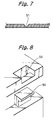
- a V-shaped groove 51 is formed in each of the contiguous sides of the walls 50a through 50h in order to limit a foldable angle.
- the angle of the letter V is selected in accordance with the angle by which each contiguous side is to be folded. For example, when the angle of the letter V is 90 degrees, nearby walls contiguous with each other via the groove 51 can be folded by substantially 90 degrees in the direction in which the surfaces forming the letter V contact each other. On the other hand, the nearby walls can be folded up to contact each other when folded in the other direction in which the surfaces forming the letter V move away from each other.
- tongues 52 protrude from one of the adjoining separate edges of the walls 50a through 50h.
- Recesses 53 are formed in the other of the adjoining separate edges of the walls 50a through 50h.
- the tongues 52 and recesses 53 constitute fastening means for fastening nearby walls 50a through 50h.
- the walls 50a through 50h in the form of a flat sheet are folded inward in a suitable sequence with the tongues 52 mating or engaging with recesses 53.
- the box 50 can therefore be framed or put together without resorting to any tool.
- FIG. 9 shows the box 50 in a developed position with the outer surfaces of the box 50 facing upward.
- the box 50 in the position shown in FIG. 9 is folded into a substantially flat structure such that the wall 50c lies on the wall 50f.
- the widthwise dimension of the box 50 is halved.
- the wall 50g protruding downward from the box 50 is folded.
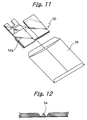
- the box 50 so folded up is small and thin enough to be put in an envelope 59 having a suitable size.
- a margin available with the V-shaped groove 51 at the time of folding is short. For this reason, as shown in FIG. 12, a groove 54 in the form of a letter W is formed in the contiguous side of the wall 50g.
- the mouth portion 21 of the bag 20 is fitted to the wall 50d of the box 50.
- guide portions 58 are formed integrally with the wall 50d in order to receive the slider 25 of the mouth portion 21 while guiding the slider 25.
- the bag 20 is fitted to the box 50 by the following procedure. As shown in FIG. 2, the walls 50c through 50h are folded in the form of a box while the walls 50a and 50b are left flat.
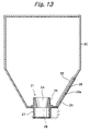
- the bag 20 has its outlet portion 27 closed by the cap 28 in order to prevent the toner from leaking, as indicated by a dash-and-dots line in FIG. 13. Subsequently, the slider 25 of the mouth portion 21 is slid into the guide portions 58. In this manner, the bag 20 is easily received in the box 50. Thereafter, the walls 50a and 50b are folded to fully frame the box 50. At this instant, the tongues 52 and recesses 53 are caused to mate or engage with each other between the walls 50a and 50b and the wall 50h.
- a seal 60 may be wrapped around all the side surfaces of the toner container 2.
- the seal 60 may be implemented by a thermally shrinkable seal by way of example. Further, the seal 60 may be provided with a shrink wrap 61 in order to allow the box 50 to be easily unfolded by hand. As shown in FIG. 15, the seal 60 may be replaced with an adhesive seal 62 adhered to the walls 50a and 50b folded last and the wall 50h.
- the wall 50a is formed with a fitting portion 55 for fitting the cap 28.
- the cap 28 is removed from the outlet portion 27 and then fitted in the fitting portion 55, as indicated by a solid line in FIG. 13. This prevents the cap 28 from obstructing the operation for mounting the toner container 2 to the apparatus body.
- the toner container 2 set on the apparatus body runs out of toner, it is picked up from the apparatus body. After the seal, if present, has been removed, the empty bag 20 is released from the box 50.
- the box 50 can be folded up in a small size and is therefore easy to transport or store while occupying a minimum of space. This noticeably reduces the cost necessary for the box 50 to be distributed from the user's station to the manufacturer's station. Moreover, if the box 50 is formed of a material having certain durability, then it can be repeatedly used a plurality of times and therefore contributes a great deal to cost reduction.
- the bag 20 is burned for reuse or similar purpose.
- the flexible bag portion 22 is empty and can therefore be transported or otherwise dealt with at an extremely low cost like the box 50.
- toner containers storing the black toner are identical in size, so that a person is apt to select a wrong toner container.
- mating means of a particular color is assigned to each mount portion of the apparatus body and corresponding one of the toner containers. This prevents each toner container from being set in an unexpected mount portion.
- the mating means, or toner distinguishing means is implemented by arcuate recesses 57 formed in the box 50 and capable of mating with projections, not shown, positioned in a preselected mount portion included in the apparatus body. The position of the recesses 57 differs from one toner to another toner.
- the recesses 57 may be formed in the slider 25 of the mouth portion 21, although not shown specifically.
- the recesses 57 formed in the slider 25 are advantageous over the recesses 57 formed in the box 50 in that it is not necessary to fabricate a particular box 50, which is repeatedly usable, for each color.
- the illustrative embodiment additionally includes recesses 56 formed in the box 50 and playing the role of model distinguishing means.
- the model distinguishing means limits the model of an image forming apparatus to which the toner container 2 is applicable.
- each apparatus body is provided with projections, not shown, capable of mating with the recesses 56 at a particular position.
- FIG. 16 shows an alternative embodiment of the present invention.
- a box 50' is openable in a right-and-left direction like a bivalve.
- the box 50' should preferably be openable along a diagonal line, as seen from the above, so that it can be widely opened to further facilitate the attachment of the bag not shown.
- the box 50' cannot be developed, it also saves space if a plurality of such boxes are stacked in the opened position.
- FIG. 17 shows another alternative embodiment of the present invention.
- a box 50" is constantly open at a portion corresponding to one wall, i.e., one side wall in the illustrative embodiment.
- the box 50" allows even the operator of the apparatus to easily attach and detach the bag 20 from the box 50".
- the walls 50a and 50b of the previous embodiment are absent in the box 50", so that the box 50" can be developed or folded up in a small size.
- the bag 20 of the toner container 2 is flexible while the box 50 can be folded up in a small size or developed in the form of a flat sheet.
- the toner container 2 is therefore easy to handle at the time of transport or storage while saving space, compared to a hard case.
- the bag 20 is collected by the manufacturer and then recycled, reused or burned.
- the box 50 with the above advantages noticeably reduces the cost necessary for the collection and distribution thereof.
- the mouth portion 21, bag portion 22 and seal valve 23 of the bag 20 should preferably be formed of the same material or materials belonging to the same series, so that they do not have to be classified at the time of recycling.
- the present invention provides a toner container including a flexible bag accommodated in a box.
- the box prevents the flexible bag from falling down when set on an image forming apparatus. Further, the box is foldable and therefore reduces the collection and distribution costs of the toner container to a significant degree. Moreover, the box is easy to fold and unfold and can be repeatedly used.
Landscapes
- Physics & Mathematics (AREA)
- General Physics & Mathematics (AREA)
- Packages (AREA)
- Dry Development In Electrophotography (AREA)
- Bag Frames (AREA)
- Ink Jet (AREA)
Applications Claiming Priority (4)
| Application Number | Priority Date | Filing Date | Title |
|---|---|---|---|
| JP2000035919 | 2000-02-14 | ||
| JP2000035919 | 2000-02-14 | ||
| JP2001006924 | 2001-01-15 | ||
| JP2001006924A JP4157681B2 (ja) | 2000-02-14 | 2001-01-15 | トナー収納容器 |
Publications (3)
| Publication Number | Publication Date |
|---|---|
| EP1126328A2 true EP1126328A2 (de) | 2001-08-22 |
| EP1126328A3 EP1126328A3 (de) | 2002-01-02 |
| EP1126328B1 EP1126328B1 (de) | 2010-01-20 |
Family
ID=26585337
Family Applications (1)
| Application Number | Title | Priority Date | Filing Date |
|---|---|---|---|
| EP01102882A Expired - Lifetime EP1126328B1 (de) | 2000-02-14 | 2001-02-14 | Pulverbehälter, Verfahren zu dessen Zusammenbau und Bilderzeugungsgerät |
Country Status (10)
| Country | Link |
|---|---|
| US (1) | US6648218B2 (de) |
| EP (1) | EP1126328B1 (de) |
| JP (1) | JP4157681B2 (de) |
| KR (1) | KR100392049B1 (de) |
| CN (1) | CN1237409C (de) |
| DE (1) | DE60141094D1 (de) |
| MX (1) | MXPA01001560A (de) |
| MY (1) | MY130181A (de) |
| SG (1) | SG115361A1 (de) |
| TW (1) | TWI257535B (de) |
Cited By (4)
| Publication number | Priority date | Publication date | Assignee | Title |
|---|---|---|---|---|
| EP1184738A1 (de) | 2000-08-31 | 2002-03-06 | Ricoh Company, Ltd. | Behälter, seine Tragstruktur und Bilderzeugungsgerät |
| US7088945B2 (en) | 2000-09-28 | 2006-08-08 | Ricoh Company, Ltd. | Toner supply unit and image forming apparatus |
| US7209687B2 (en) | 2001-01-31 | 2007-04-24 | Ricoh Company, Ltd. | Toner container and image forming apparatus using the same |
| WO2020013838A1 (en) * | 2018-07-13 | 2020-01-16 | Hewlett-Packard Development Company, L.P. | Box with alignment structures |
Families Citing this family (36)
| Publication number | Priority date | Publication date | Assignee | Title |
|---|---|---|---|---|
| CN1900837B (zh) | 2000-02-17 | 2012-10-03 | 株式会社理光 | 墨粉收纳容器、补给墨粉的方法及墨粉补给装置 |
| JP4194254B2 (ja) * | 2000-06-22 | 2008-12-10 | 株式会社リコー | トナー収納容器および画像形成装置 |
| JP4220798B2 (ja) * | 2002-09-20 | 2009-02-04 | 株式会社リコー | 粉体収納容器 |
| JP4584659B2 (ja) * | 2003-09-30 | 2010-11-24 | 株式会社リコー | 画像形成用粉体を内包する易変形性容器用容器収納箱 |
| EP1589384B1 (de) * | 2004-04-23 | 2020-01-08 | Ricoh Company, Ltd. | Entwicklerbehälter |
| JP4713295B2 (ja) * | 2004-11-09 | 2011-06-29 | 株式会社リコー | 減容装置及びトナー補給装置 |
| RU2007121744A (ru) * | 2004-11-09 | 2008-12-20 | Джон СТИВЕНСОН (GB) | Мешочный картридж с не допускающим скручивания хомутом |
| EP1868916B1 (de) * | 2005-03-04 | 2010-08-04 | Graphic Packaging International, Inc. | Beutel in einer schachtel |
| JP4755881B2 (ja) * | 2005-10-24 | 2011-08-24 | 株式会社リコー | 容器収納装置、該容器収納装置を備えた搬送装置及び画像形成装置 |
| USD590117S1 (en) | 2007-05-03 | 2009-04-07 | Johnsondiversey, Inc. | Floor maintenance tool |
| USD592819S1 (en) | 2007-05-03 | 2009-05-19 | Johnsondiversey, Inc. | Valve assembly for a floor maintenance tool |
| USD602664S1 (en) | 2007-05-03 | 2009-10-20 | Johnsondiversey, Inc. | Floor maintenance tool |
| US20090285949A1 (en) * | 2008-05-15 | 2009-11-19 | Wendell Brown | Expandable Food Container |
| US8276806B2 (en) * | 2008-11-21 | 2012-10-02 | Graphic Packaging International, Inc. | Carton for flowable material |
| US8720769B2 (en) | 2009-09-15 | 2014-05-13 | Packaging Corporation Of America | Beverage container |
| JP5162650B2 (ja) * | 2010-12-20 | 2013-03-13 | 富士ゼロックス株式会社 | 液袋接続部材 |
| MX356824B (es) | 2011-03-30 | 2018-06-15 | Ricoh Co Ltd | Recipiente de almacenamiento de polvo y aparato de formación de imágenes. |
| US9415997B2 (en) * | 2012-04-26 | 2016-08-16 | Southern Champion Tray | Bottle in box container |
| CH705673A1 (fr) * | 2011-10-28 | 2013-04-30 | Codefine Sa | Dispositif de stabilisation de valves de vidange et/ou remplissage d'un conteneur souple destiné au transport de liquides ou de matières pulvérulentes. |
| JP5857783B2 (ja) * | 2012-02-17 | 2016-02-10 | 株式会社リコー | ノズル、画像形成装置、及び粉体導出方法 |
| US20140001180A1 (en) * | 2012-06-27 | 2014-01-02 | Hood Packaging Corporation | Liquid pouch with dispensing fitment and support pitcher |
| GB2546189A (en) * | 2014-10-07 | 2017-07-12 | Frugalpac Ltd | Container |
| JP6418896B2 (ja) | 2014-10-27 | 2018-11-07 | キヤノン株式会社 | 現像剤収納ユニットの再生産方法 |
| JP6410564B2 (ja) * | 2014-10-27 | 2018-10-24 | キヤノン株式会社 | 現像剤収納ユニットの再生産方法 |
| JP6584062B2 (ja) * | 2014-10-27 | 2019-10-02 | キヤノン株式会社 | 再生産方法 |
| KR102229766B1 (ko) * | 2016-05-12 | 2021-03-19 | 휴렛-팩커드 디벨롭먼트 컴퍼니, 엘.피. | 축조 재료 용기 |
| WO2017194153A1 (en) * | 2016-05-12 | 2017-11-16 | Hewlett-Packard Development Company L.P. | Build material container |
| US10162288B2 (en) | 2016-09-23 | 2018-12-25 | Clover Technologies Group, Llc | System and method of remanufacturing a toner container |
| US9946199B1 (en) | 2016-09-23 | 2018-04-17 | Clover Technologies Group, Llc | System and method of filling a toner container |
| FI128014B (en) * | 2017-02-16 | 2019-07-31 | Inno Vai Oy | Box for a Bag-in-Box package |
| US10974892B1 (en) * | 2017-03-28 | 2021-04-13 | Monroe Zafir | Intermediate bulk container cartridge |
| EP3434449B1 (de) * | 2017-07-28 | 2021-07-14 | Hewlett-Packard Development Company, L.P. | Baumaterialbehälter |
| EP3434448A1 (de) * | 2017-07-28 | 2019-01-30 | Hewlett-Packard Development Company, L.P. | Baumaterialbehälter |
| KR102390147B1 (ko) * | 2018-08-30 | 2022-04-25 | 휴렛-팩커드 디벨롭먼트 컴퍼니, 엘.피. | 현상 카트리지와 본체 간의 인터페이스를 통해 본체에 연결되는 토너 리필 카트리지 |
| US10919680B1 (en) | 2018-10-08 | 2021-02-16 | Packaging Corporation Of America | Liquid beverage container |
| CN110589200A (zh) * | 2019-09-30 | 2019-12-20 | 樱拓(上海)生物科技有限公司 | 一种液体包装袋结构 |
Family Cites Families (23)
| Publication number | Priority date | Publication date | Assignee | Title |
|---|---|---|---|---|
| US3526566A (en) * | 1968-08-20 | 1970-09-01 | Downingtown Paper Co | Method and apparatus for scoring paperboard and product produced thereby |
| US4120420A (en) * | 1978-02-16 | 1978-10-17 | The Procter & Gamble Company | Lined parallelepipedal package for dispensing flowable materials |
| US4373929A (en) * | 1979-01-22 | 1983-02-15 | Smith Paul W | Method and apparatus for cutting and scoring folding container blanks |
| JPS5816267A (ja) * | 1981-07-22 | 1983-01-29 | Konishiroku Photo Ind Co Ltd | 粉体供給方法 |
| US4523615A (en) * | 1983-03-17 | 1985-06-18 | International Business Machines Corporation | Method and apparatus for in situ purging a xerographic developer |
| US4502514A (en) * | 1983-07-18 | 1985-03-05 | International Business Machines Corporation | Toner cartridge and method of replenishing toner to a xerographic device |
| DE3915899A1 (de) * | 1989-05-16 | 1990-11-22 | Edelmann Carl Gmbh | Verpackungsbehaelter aus karton mit innenbeutel zur aufnahme von fluessigkeiten |
| DE9000528U1 (de) * | 1990-01-18 | 1990-03-22 | Carl Edelmann Verpackungstechnik GmbH, 7920 Heidenheim | Innenbeutelpackung |
| JPH03269461A (ja) * | 1990-03-19 | 1991-12-02 | Konica Corp | 粉体補給装置 |
| US5392963A (en) | 1993-06-01 | 1995-02-28 | Hewlett-Packard Company | Refurbished toner cartridge |
| JP2605130Y2 (ja) * | 1993-08-23 | 2000-06-26 | 株式会社細川洋行 | 容器装置 |
| JP2605131Y2 (ja) * | 1993-08-23 | 2000-06-26 | 株式会社細川洋行 | 柔軟容器の保持器 |
| JPH07134484A (ja) | 1993-11-11 | 1995-05-23 | Ricoh Co Ltd | トナーカートリッジ及びトナー供給方法 |
| JPH09142534A (ja) | 1995-02-22 | 1997-06-03 | Sangyo Gijutsu Kenkyusho:Kk | 流動物の輸送方法 |
| JP3437332B2 (ja) | 1995-07-10 | 2003-08-18 | キヤノン株式会社 | 粉体供給用容器と該粉体供給用容器の製造方法及び粉体供給方法 |
| US5715992A (en) * | 1995-09-26 | 1998-02-10 | J & M Coffee Container Company, Inc. | Beverage container |
| JPH11119536A (ja) | 1997-10-20 | 1999-04-30 | Canon Inc | 乾式電子写真用トナーボトル |
| JP2000194182A (ja) * | 1998-10-19 | 2000-07-14 | Ricoh Co Ltd | トナー収納容器および該トナー収納容器を用いる画像形成装置 |
| TWI272461B (en) | 1998-12-22 | 2007-02-01 | Ricoh Kk | Toner container and image forming method and apparatus using the same |
| JP3711777B2 (ja) * | 1999-02-16 | 2005-11-02 | コニカミノルタホールディングス株式会社 | 粉体収納容器 |
| JP3967078B2 (ja) * | 2000-02-29 | 2007-08-29 | 株式会社リコー | 粉体収納容器および該容器の組み立て方法 |
| JP4194254B2 (ja) * | 2000-06-22 | 2008-12-10 | 株式会社リコー | トナー収納容器および画像形成装置 |
| JP4351814B2 (ja) * | 2000-07-21 | 2009-10-28 | 株式会社リコー | カラー画像形成装置 |
-
2001
- 2001-01-15 JP JP2001006924A patent/JP4157681B2/ja not_active Expired - Lifetime
- 2001-02-06 CN CNB011030992A patent/CN1237409C/zh not_active Expired - Lifetime
- 2001-02-09 US US09/779,607 patent/US6648218B2/en not_active Expired - Lifetime
- 2001-02-10 MY MYPI20010605A patent/MY130181A/en unknown
- 2001-02-12 MX MXPA01001560A patent/MXPA01001560A/es active IP Right Grant
- 2001-02-12 SG SG200100753A patent/SG115361A1/en unknown
- 2001-02-13 TW TW090103159A patent/TWI257535B/zh not_active IP Right Cessation
- 2001-02-13 KR KR10-2001-0006950A patent/KR100392049B1/ko not_active Expired - Lifetime
- 2001-02-14 DE DE60141094T patent/DE60141094D1/de not_active Expired - Lifetime
- 2001-02-14 EP EP01102882A patent/EP1126328B1/de not_active Expired - Lifetime
Cited By (7)
| Publication number | Priority date | Publication date | Assignee | Title |
|---|---|---|---|---|
| EP1184738A1 (de) | 2000-08-31 | 2002-03-06 | Ricoh Company, Ltd. | Behälter, seine Tragstruktur und Bilderzeugungsgerät |
| US6501913B2 (en) | 2000-08-31 | 2002-12-31 | Ricoh Company, Ltd. | Container, its support structure, and image formation apparatus |
| US7088945B2 (en) | 2000-09-28 | 2006-08-08 | Ricoh Company, Ltd. | Toner supply unit and image forming apparatus |
| US7209687B2 (en) | 2001-01-31 | 2007-04-24 | Ricoh Company, Ltd. | Toner container and image forming apparatus using the same |
| WO2020013838A1 (en) * | 2018-07-13 | 2020-01-16 | Hewlett-Packard Development Company, L.P. | Box with alignment structures |
| CN112074412A (zh) * | 2018-07-13 | 2020-12-11 | 惠普发展公司,有限责任合伙企业 | 具有对齐结构的盒 |
| CN112074412B (zh) * | 2018-07-13 | 2022-06-07 | 惠普发展公司,有限责任合伙企业 | 具有对齐结构的盒 |
Also Published As
| Publication number | Publication date |
|---|---|
| MXPA01001560A (es) | 2002-08-06 |
| EP1126328A3 (de) | 2002-01-02 |
| US20010021325A1 (en) | 2001-09-13 |
| CN1309335A (zh) | 2001-08-22 |
| EP1126328B1 (de) | 2010-01-20 |
| HK1036110A1 (en) | 2001-12-21 |
| TWI257535B (en) | 2006-07-01 |
| MY130181A (en) | 2007-06-29 |
| JP4157681B2 (ja) | 2008-10-01 |
| KR20010102831A (ko) | 2001-11-16 |
| KR100392049B1 (ko) | 2003-07-22 |
| JP2001301847A (ja) | 2001-10-31 |
| SG115361A1 (en) | 2005-10-28 |
| CN1237409C (zh) | 2006-01-18 |
| US6648218B2 (en) | 2003-11-18 |
| DE60141094D1 (de) | 2010-03-11 |
Similar Documents
| Publication | Publication Date | Title |
|---|---|---|
| US6648218B2 (en) | Powder container, method of assembling the same and image forming apparatus | |
| US6519436B2 (en) | Toner powder container for storing toner applicable to an electrographic image forming apparatus, a method at assembling the same, and a method of reducing the volume of the same | |
| EP1184738B1 (de) | Behälter, seine Tragstruktur und Bilderzeugungsgerät | |
| EP1475674B1 (de) | Bag-in-Box-Anordnung zum Speichern von Toner | |
| US7389071B2 (en) | Apparatuses for image forming capable of effectively conveying developer therefrom and a method of effectively forming a reinforcing member adhering to the apparatuses | |
| EP1555582B1 (de) | Tonerbehälter und damit versehene Bilderzeugungsvorrichtung | |
| EP1174773B1 (de) | Farbbilderzeugungsvorrichtung, Tonernachfüllvorrichtung und Tonerbehälter | |
| US8064807B2 (en) | Developer supply system and image forming apparatus incorporating same | |
| US6532352B2 (en) | Powder container and image forming apparatus using same | |
| US20040165913A1 (en) | Toner agitating device and toner conveying device for an image forming apparatus | |
| JP4048011B2 (ja) | 画像形成装置 | |
| JP4461186B2 (ja) | トナー収納容器および画像形成装置 | |
| JP2006113615A (ja) | 画像形成装置 | |
| JPH11282237A (ja) | トナー収納容器 |
Legal Events
| Date | Code | Title | Description |
|---|---|---|---|
| PUAI | Public reference made under article 153(3) epc to a published international application that has entered the european phase |
Free format text: ORIGINAL CODE: 0009012 |
|
| 17P | Request for examination filed |
Effective date: 20010214 |
|
| AK | Designated contracting states |
Kind code of ref document: A2 Designated state(s): AT BE CH CY DE DK ES FI FR GB GR IE IT LI LU MC NL PT SE TR Kind code of ref document: A2 Designated state(s): DE ES FR GB IT NL |
|
| AX | Request for extension of the european patent |
Free format text: AL;LT;LV;MK;RO;SI |
|
| PUAL | Search report despatched |
Free format text: ORIGINAL CODE: 0009013 |
|
| AK | Designated contracting states |
Kind code of ref document: A3 Designated state(s): AT BE CH CY DE DK ES FI FR GB GR IE IT LI LU MC NL PT SE TR |
|
| AX | Request for extension of the european patent |
Free format text: AL;LT;LV;MK;RO;SI |
|
| 17Q | First examination report despatched |
Effective date: 20011205 |
|
| AKX | Designation fees paid |
Free format text: DE ES FR GB IT NL |
|
| GRAP | Despatch of communication of intention to grant a patent |
Free format text: ORIGINAL CODE: EPIDOSNIGR1 |
|
| GRAS | Grant fee paid |
Free format text: ORIGINAL CODE: EPIDOSNIGR3 |
|
| GRAA | (expected) grant |
Free format text: ORIGINAL CODE: 0009210 |
|
| AK | Designated contracting states |
Kind code of ref document: B1 Designated state(s): DE ES FR GB IT NL |
|
| REG | Reference to a national code |
Ref country code: GB Ref legal event code: FG4D |
|
| REF | Corresponds to: |
Ref document number: 60141094 Country of ref document: DE Date of ref document: 20100311 Kind code of ref document: P |
|
| REG | Reference to a national code |
Ref country code: NL Ref legal event code: VDEP Effective date: 20100120 |
|
| PG25 | Lapsed in a contracting state [announced via postgrant information from national office to epo] |
Ref country code: ES Free format text: LAPSE BECAUSE OF FAILURE TO SUBMIT A TRANSLATION OF THE DESCRIPTION OR TO PAY THE FEE WITHIN THE PRESCRIBED TIME-LIMIT Effective date: 20100501 Ref country code: NL Free format text: LAPSE BECAUSE OF FAILURE TO SUBMIT A TRANSLATION OF THE DESCRIPTION OR TO PAY THE FEE WITHIN THE PRESCRIBED TIME-LIMIT Effective date: 20100120 |
|
| PLBE | No opposition filed within time limit |
Free format text: ORIGINAL CODE: 0009261 |
|
| STAA | Information on the status of an ep patent application or granted ep patent |
Free format text: STATUS: NO OPPOSITION FILED WITHIN TIME LIMIT |
|
| 26N | No opposition filed |
Effective date: 20101021 |
|
| PG25 | Lapsed in a contracting state [announced via postgrant information from national office to epo] |
Ref country code: IT Free format text: LAPSE BECAUSE OF FAILURE TO SUBMIT A TRANSLATION OF THE DESCRIPTION OR TO PAY THE FEE WITHIN THE PRESCRIBED TIME-LIMIT Effective date: 20100120 |
|
| REG | Reference to a national code |
Ref country code: FR Ref legal event code: PLFP Year of fee payment: 16 |
|
| REG | Reference to a national code |
Ref country code: FR Ref legal event code: PLFP Year of fee payment: 17 |
|
| REG | Reference to a national code |
Ref country code: FR Ref legal event code: PLFP Year of fee payment: 18 |
|
| PGFP | Annual fee paid to national office [announced via postgrant information from national office to epo] |
Ref country code: DE Payment date: 20200219 Year of fee payment: 20 Ref country code: GB Payment date: 20200219 Year of fee payment: 20 |
|
| PGFP | Annual fee paid to national office [announced via postgrant information from national office to epo] |
Ref country code: FR Payment date: 20200219 Year of fee payment: 20 |
|
| REG | Reference to a national code |
Ref country code: DE Ref legal event code: R071 Ref document number: 60141094 Country of ref document: DE |
|
| REG | Reference to a national code |
Ref country code: GB Ref legal event code: PE20 Expiry date: 20210213 |
|
| PG25 | Lapsed in a contracting state [announced via postgrant information from national office to epo] |
Ref country code: GB Free format text: LAPSE BECAUSE OF EXPIRATION OF PROTECTION Effective date: 20210213 |