EP1125734A1 - Vorrichtung zum Antreiben von Druckzylindern - Google Patents
Vorrichtung zum Antreiben von Druckzylindern Download PDFInfo
- Publication number
- EP1125734A1 EP1125734A1 EP01101602A EP01101602A EP1125734A1 EP 1125734 A1 EP1125734 A1 EP 1125734A1 EP 01101602 A EP01101602 A EP 01101602A EP 01101602 A EP01101602 A EP 01101602A EP 1125734 A1 EP1125734 A1 EP 1125734A1
- Authority
- EP
- European Patent Office
- Prior art keywords
- gear
- cylinder
- printing
- printing unit
- sun gear
- Prior art date
- Legal status (The legal status is an assumption and is not a legal conclusion. Google has not performed a legal analysis and makes no representation as to the accuracy of the status listed.)
- Granted
Links
- 238000007639 printing Methods 0.000 title claims abstract description 63
- 230000007246 mechanism Effects 0.000 claims description 18
- 238000007645 offset printing Methods 0.000 claims description 9
- 239000000463 material Substances 0.000 description 5
- 241000094396 Bolitoglossa carri Species 0.000 description 1
- 238000004519 manufacturing process Methods 0.000 description 1
Images


Classifications
-
- B—PERFORMING OPERATIONS; TRANSPORTING
- B41—PRINTING; LINING MACHINES; TYPEWRITERS; STAMPS
- B41F—PRINTING MACHINES OR PRESSES
- B41F13/00—Common details of rotary presses or machines
- B41F13/008—Mechanical features of drives, e.g. gears, clutches
-
- B—PERFORMING OPERATIONS; TRANSPORTING
- B41—PRINTING; LINING MACHINES; TYPEWRITERS; STAMPS
- B41P—INDEXING SCHEME RELATING TO PRINTING, LINING MACHINES, TYPEWRITERS, AND TO STAMPS
- B41P2213/00—Arrangements for actuating or driving printing presses; Auxiliary devices or processes
- B41P2213/70—Driving devices associated with particular installations or situations
- B41P2213/73—Driving devices for multicolour presses
- B41P2213/734—Driving devices for multicolour presses each printing unit being driven by its own electric motor, i.e. electric shaft
Definitions
- the present invention relates to a device for driving Printing unit cylinders in a printing press according to the preamble of claim 1.
- the printing unit cylinders On the printing unit cylinders of printing machines, a printing material, e.g. B. paper, printed.
- the printing unit cylinders comprise a plate cylinder and a blanket cylinder.
- a printing plate mounted on the plate cylinder contacts the blanket mounted on the blanket cylinder while one Material web or a sheet of material between the rubber blanket and one Counter pressure cylinder is passed through.
- ink is applied via inking rollers applied the plate cylinder and the thus colored image on the rubber blanket and from transferred there to the web or the arch.
- the impression cylinder can be designed as a further blanket cylinder.
- the plate cylinder and the blanket cylinder are made by one on the drive side the printing machine arranged drive mechanism, which is usually a Gearbox for driving the individual printing cylinder includes.
- the Drive mechanism can be over a single engine or over multiple engines are driven.
- Hitachi-Seiko machines for example, have one Two-motor drive for driving two printing unit cylinders in a four-cylinder printing unit.
- Heidelberg Web Press, Inc. machines have one Three-motor drive for driving three printing unit cylinders in a four-cylinder printing unit.
- the plate cylinder From Put the blanket cylinder or the blanket cylinder off the impression cylinder.
- the mechanisms by which the printing couple cylinders are moved are called and called shutdown mechanisms.
- US 4,309,954 describes a drive for a printing couple cylinder in one Flexographic printing machine, in which the printing unit cylinder carrying the printing plate over a planetary gear is driven by a main drive. Due to the Design of the planetary gear with two opposite one another in one It is internal ring gear arranged, supported on a sun gear planet gears not possible with the described planetary gear, the pressure plate cylinder from turn off adjacent printing unit cylinder without the entire planetary gear as to move such and the main drive shaft leading to the planetary gear, or to design it to be angularly movable in a complex manner.
- US 4,953,461 describes a device for register adjustment of Printing unit cylinders in which the register adjustment as such by means of a so-called Harmonic-Drive drive takes place, which with the drive pin of the pressure plate cylinder coupled and provided on the outside with a drive sprocket.
- the Drive sprocket is rotated by a drive motor, not shown and in turn drives an associated drive gear for the assigned one Blanket cylinder, which on a corresponding journal of the Blanket cylinder is attached.
- the axle pin of the rubber blanket cylinder is exaggerating a drive shaft to a sun gear of a planetary gear, which in turn Drive gears are coupled to an input shaft of the harmonic drive drive, to make them spin.
- the scripture gives no indication that Plate cylinder or the blanket cylinder through a planetary gear through To drive the main drive motor.
- the press manufacturer MAN Roland uses a direct drive for one Blanket cylinder.
- the engine is moved during the shutdown and drives the Blanket cylinder in a ratio of 1: 1.
- the object of the present invention is to use smaller drive motors for printing unit cylinders and the operation of drive motors with higher ones To allow speed.
- Another or alternative task is one to allow the engine to be arranged in a stationary manner even when the cylinders are switched off.
- the planetary gear according to the invention enables the use of motors with higher ones Speed because the sun gear rotates at a higher rotational speed than the internal ring gear. In this way, a lower inertia ratio remains on the motor receive.
- the higher engine speed makes the electronic better Control of the speed of the printing unit cylinder possible.
- the printing unit cylinder is preferably a blanket cylinder or a Plate cylinder of an offset printing machine.
- the printing couple cylinder is preferably in a first position and in a second position movable, z. B. in the first position by one Print job and the second position is a print job.
- the motor preferably remains in both the first position and the second position. the printing unit cylinder in the same position, while the inner ring gear with the Printing cylinder is moved, but continues to mesh with the planet gear, d. H. in Meshing is.
- the device according to the invention preferably further comprises a switch-on and switch-off mechanism which is connected to the printing group cylinder and which comprises a pivotable lever for moving the printing group cylinder.
- the printing unit cylinder can be designed as a conventional cylinder having a channel or as a cantilevered cylinder which has a sleeve, such as. B. carries a canal blanket or a canal-free printing plate, which over the free end of the printing unit cylinder, for. B. using blown air, can be pushed axially onto this.
- the gear ratio of the planetary gear is preferably 4: 1, i. H. the sun gear and the motor preferably rotates at four times the speed of rotation Internal ring gear and the printing unit cylinder.
- the printing unit cylinder can preferably be a plate cylinder Offset printing machine, which further comprises a blanket cylinder, the one via a drive gear connected to the inner ring gear and one with this connected driven gear, which is attached to the blanket cylinder, driven becomes. If the blanket cylinder and the plate cylinder are the same size, that has Drive gear and the driven gear preferably also the same size.
- the planet gear preferably comprises a device for avoiding gear play in gears.
- a side gear arrangement can be used be used.
- the motor can be arranged in such a way that it is axially displaceable and with a spiral gear is coupled to a movement in the circumferential direction Allow register setting.
- the circumferential register can also be accessed via the Drive motors can be set.
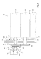
- FIG. 1 shows a partial top view of an offset printing press 1 with a drive-side frame 2, a plate cylinder 10 and a blanket cylinder 20th
- a web of material 3 e.g. B. a web of newsprint is up between passed through the blanket cylinder 20 and an impression cylinder 30, wherein the impression cylinder 30 preferably as a further blanket cylinder with a this assigned plate cylinder is formed.
- the plate cylinder 10 is rotatably arranged at one end 13 in a bearing 11 is located in a lever 12.
- the lever 12 is on his attached lower end via a pivot point 101 to the frame 2 and at its upper End via an air piston 102 connected to the frame 2 and the lever 12 movable.
- the lever 12 and the air piston 102 form a connection and Parking mechanism by means of which the plate cylinder 10 from the blanket cylinder 20th can be moved away in the direction indicated by arrow 100, as in FIG. 1 is shown.
- an eccentric or another can be used in the same way known cylinder shut-off mechanism can be used.
- the plate cylinder 10 is driven by a motor 40 arranged in a housing 42 driven.
- the motor 40 comprises a drive shaft 41.
- the housing 42 is stationary, what in the sense of this application means that the central axis of the drive shaft 41 is always on remains in the same position.
- the housing 42 can be axially displaceable, by z. B. is arranged with a movable motor on a rail.
- the drive shaft 41 is connected to a sun gear 51 of a planetary gear 50 and is preferably arranged coaxially to the axis of rotation of the plate cylinder 10.
- the Sun gear 51 also preferably drives a single planet gear 52, which preferably is rotatably supported in the housing 42.
- the axis of the planet gear 52 is with respect to the axis of the sun gear 51 fixed, which means in the sense of this application that the planet gear 52 remains in engagement with the sun gear 51 even if the axes of the internal ring gear 53 and the planet gear 52 are moved away from each other to a small extent, for. B. at Starting and stopping the printing unit cylinder.
- the planet gear 52 drives a ring gear, for. B. an internal ring gear 53, which is preferably is firmly connected to one end 13 of the plate cylinder 10.
- the planetary gear 50 is shown in more detail in FIG. 2.
- Fig. 2 shows the plate cylinder 10 in the print job.
- the internal ring gear 53 has dotted lines Teeth 153 on.
- the sun gear 51 has teeth 151 which fit into the teeth 152 of the Intervene planetary gear 52.
- the teeth 152 are also with the teeth 153 of the Internal ring gear engaged.
- the sun gear 51 can, for example, 30 teeth Planetary gear can have 45 teeth and the internal ring gear 53 can have 120 teeth, so that a Reduction ratio of 4: 1 exists.
- the inner ring gear 53 is also laterally in the Moved in the direction of arrow 100.
- the sun gear 51 and the planet gear 52 remain but preferably stationary.
- Fig. 3 the planetary gear 50 is shown in the parked state of the plate cylinder. In this state, teeth 151 and 152 remain fully engaged with each other because the motor 40 and the housing 42 are stationary. The teeth 153 move away from the Teeth 152 of the planet gear 52, but continue to mesh with each other even if they are not fully engaged.
- the length of the teeth 153 and 152 is preferably selected such that the teeth 152 and 153 comb each other even when the plate cylinder is in the parked state. Comb as well also the teeth of the drive gears 54 and 55 of the printing couple cylinders 10 and 20 with each other in the parked state.
- the plate cylinder 10 and the blanket cylinder 20 in parked state continue to be rotated by the drive motor 40, for. B. one flying plate change, in which the plate cylinder through the Drive motor braked down to standstill and then back up to Production speed is accelerated.
- the teeth 152 of the planet gear 52 can be a device for avoiding Gear play include, e.g. B. a idler gear.
- the blanket cylinder 30 and the plate cylinder associated therewith can be similar Have drive and shutdown mechanisms. However, it is also possible to use these cylinders by the motor 40 via a gear, e.g. B. connected to the drive gear 55 Gears to drive.
- a gear e.g. B. connected to the drive gear 55 Gears to drive.
- the motor 40 can also by means of an electronic control, for. B. one Microprocessor to be controlled so that the speed of the engine changes can be.
- the drive unit, the plate cylinder in the described embodiment directly or drives via the planetary gear 50, can instead or in the same way alternatively drive the blanket cylinder.
Landscapes
- Engineering & Computer Science (AREA)
- Mechanical Engineering (AREA)
- Rotary Presses (AREA)
- Inking, Control Or Cleaning Of Printing Machines (AREA)
- Power Steering Mechanism (AREA)
- Valve Device For Special Equipments (AREA)
Abstract
Description
Der Druckwerkszylinder kann als ein konventioneller, einen Kanal aufweisender Zylinder ausgebildet sein oder aber als ein fliegend gelagerter Zylinder ausgebildet sein, der eine Hülse, wie z. B. ein kanalloses Gummituch oder aber auch eine kanallose Druckplatte trägt, die über das freie Ende des Druckwerkszylinders, z. B. unter Einsatz von Blasluft, axial auf diesen aufgeschoben werden kann.
- Fig. 1
- eine teilweise, schematische Draufsicht einer Ausführungsform der vorliegenden Erfindung;
- Fig. 2
- eine schematische Seitenansicht des Antriebsgetriebes der in Fig. 1 gezeigten Ausführungsform;
- Fig. 3
- das in Fig. 2 gezeigte Antriebsgetriebe nach dem Abstellen des Druckwerkszylinders; und
- Fig. 4
- eine schematische Darstellung eines Abstellhebels, wie er in Verbindung mit der in Fig. 1 gezeigten Ausführungsform eingesetzt werden kann.
- 1
- Offsetdruckmaschine
- 2
- antriebsseitiger Rahmen
- 3
- Materialbahn
- 10
- Plattenzylinder
- 11
- Lager
- 12
- Hebel
- 13
- Ende
- 20
- Gummituchzylinder
- 22
- Abstellhebel
- 23
- Ende
- 30
- Gegendruckzylinder
- 40
- Motor
- 41
- Antriebsachse
- 42
- Gehäuse
- 50
- Planetengetriebe
- 51
- Sonnenrad
- 52
- Planetenrad
- 53
- Innenhohlrad
- 54
- Antriebsrad
- 55
- angetriebenes Rad
- 101
- Schwenkpunkt
- 102
- Kolben
- 100
- Abstellrichtung
- 151
- Zähne
- 152
- Zähne
- 153
- Zähne
Claims (12)
- Vorrichtung zum Antreiben eines Druckwerkszylinder (10, 20, 30) in einer Rotationsdruckmaschine, insbesondere einer Rollenrotations-Offsetdruckmaschine, mit einem Motor (40), welcher antriebsmäßig mit einem eine Sonnenradachse aufweisenden Sonnenrad (51) verbunden ist, einem Planetenrad (52), das um eine Planetenradachse rotiert und vom Sonnenrad (51) angetrieben wird, sowie mit einem mit dem Druckwerkszylinder (10, 20, 30) antriebsmäßig gekoppelten Ringzahnrad (53), welches vom Planetenrad (52) antreibbar ist,
dadurch gekennzeichnet,
dass das Planetenrad durch ein einzelnes Planetenrad (52) gebildet wird, dass die Achse des Planetenrades (52) bezüglich der Achse des Sonnenrades (51) in einem festen Abstand angeordnet ist, in der Weise, dass bei einer An- und Abstellbewegung des Druckwerkszylinders (10, 20, 30) die Zähne (153) des mit diesem gekoppelten Ringzahnrades (53) mit den Zähnen (152) des Planetenrades (52) in Zahneingriff bleiben. - Vorrichtung nach Anspruch 1,
dadurch gekennzeichnet,
dass der Druckwerkszylinder (10, 20, 30) als ein Gummituchzylinder (20) oder ein Plattenzylinder (10) einer Offsetdruckmaschine ausgebildet ist. - Vorrichtung nach Anspruch 1 oder 2,
dadurch gekennzeichnet,
dass der Druckwerkszylinder (10, 20, 30) in eine erste Position und in eine zweite Position bewegbar ist, wobei es sich bei der ersten Position um eine Druckanstellung und bei der zweiten Position um eine Druckabstellung handelt. - Vorrichtung nach Anspruch 3,
dadurch gekennzeichnet,
dass der Motor (40) sowohl in der ersten Position als auch in der zweiten Position des Druckwerkszylinders (10, 20, 30) in derselben Position bleibt. - Vorrichtung nach einem der vorhergehenden Ansprüche,
dadurch gekennzeichnet,
dass das Sonnenrad (51) und das Planetenrad (52) auf der dem Druckwerkszylinder (10, 20, 30) gegenüber liegenden Seite des Ringzahnrades (53) angeordnet sind. - Vorrichtung nach einem der Ansprüche 3 bis 5,
gekennzeichnet durch
einen An- und Abstellmechanismus zum Bewegen des Druckwerkszylinders (10, 20, 30) in die erste und zweite Position. - Vorrichtung nach Anspruch 6,
dadurch gekennzeichnet,
dass der An- und Abstellmechanismus einen schwenkbaren Hebel (12) oder ein Stellexzenter umfasst. - Vorrichtung nach einem der vorhergehenden Ansprüche,
dadurch gekennzeichnet,
dass das Getriebeverhältnis zwischen dem Sonnenrad (51), dem Planetenrad (52) und dem Ringzahnrad (53) 4:1 beträgt. - Vorrichtung nach einem der vorhergehenden Ansprüche,
dadurch gekennzeichnet,
dass der Druckwerkszylinder (10, 20, 30) als ein Plattenzylinder (10) ausgebildet ist und dass ferner ein Gummituchzylinder (20) vorgesehen ist, der mit dem Plattenzylinder (10) über ein angetriebenes Zahnrad (55) zum Antrieb gekoppelt ist. - Vorrichtung nach einem der vorhergehenden Ansprüche,
dadurch gekennzeichnet,
dass mindestens eines der Zahnräder (51, 52, 53) eine Vorrichtung zur Vermeidung von Zahnradspiel in Getrieben umfasst. - Vorrichtung nach einem der vorhergehenden Ansprüche,
dadurch gekennzeichnet,
dass das Sonnenrad (51) koaxial zur Drehachse des Druckwerkszylinders (10, 20, 30) angeordnet ist. - Vorrichtung nach einem der vorhergehenden Ansprüche,
dadurch gekennzeichnet,
dass der Antriebsmotor (40) das Sonnenrad (51) über eine Antriebswelle (41) antreibt, welche bei angestelltem Druckwerkszylinder (10, 20, 30) koaxial zu einer mit dem Ringzahnrad (53) verbundenen Antriebswelle des Druckwerkszylinders (10, 20, 30) angeordnet ist.
Applications Claiming Priority (2)
| Application Number | Priority Date | Filing Date | Title |
|---|---|---|---|
| US499794 | 2000-02-08 | ||
| US09/499,794 US6289805B1 (en) | 2000-02-08 | 2000-02-08 | Device and method for driving a printing cylinder |
Publications (2)
| Publication Number | Publication Date |
|---|---|
| EP1125734A1 true EP1125734A1 (de) | 2001-08-22 |
| EP1125734B1 EP1125734B1 (de) | 2008-01-16 |
Family
ID=23986753
Family Applications (1)
| Application Number | Title | Priority Date | Filing Date |
|---|---|---|---|
| EP01101602A Expired - Lifetime EP1125734B1 (de) | 2000-02-08 | 2001-01-25 | Vorrichtung zum Antreiben von Druckzylindern |
Country Status (5)
| Country | Link |
|---|---|
| US (1) | US6289805B1 (de) |
| EP (1) | EP1125734B1 (de) |
| JP (1) | JP4755349B2 (de) |
| AT (1) | ATE383947T1 (de) |
| DE (2) | DE50113485D1 (de) |
Cited By (4)
| Publication number | Priority date | Publication date | Assignee | Title |
|---|---|---|---|---|
| DE10154837A1 (de) * | 2001-11-08 | 2003-07-24 | Koenig & Bauer Ag | Antrieb eines Druckwerks |
| WO2005007408A3 (de) * | 2003-07-11 | 2005-07-07 | Koenig & Bauer Ag | Druckmaschine sowie druckmaschinenanlage |
| US7077061B2 (en) | 2001-11-08 | 2006-07-18 | Koenig & Bauer Aktiengesellschaft | Drives for a printing group |
| US7114439B2 (en) | 2001-08-03 | 2006-10-03 | Koenig & Bauer Aktiengesellschaft | Printing groups of a printing press |
Families Citing this family (13)
| Publication number | Priority date | Publication date | Assignee | Title |
|---|---|---|---|---|
| JP4702916B2 (ja) * | 2001-03-05 | 2011-06-15 | 株式会社ミヤコシ | 輪転印刷機 |
| RU2262449C2 (ru) * | 2001-03-26 | 2005-10-20 | Кениг Унд Бауер Акциенгезельшафт | Привод печатного аппарата |
| US6851368B2 (en) * | 2001-08-29 | 2005-02-08 | Heidelberger Druckmaschinen Ag | Rotary printing press having a switchable speed-change gear mechanism with plant gears |
| US20040231535A1 (en) * | 2002-07-03 | 2004-11-25 | Gerner Erich Max Karl | Printing groups of a printing press |
| JP2006250202A (ja) * | 2005-03-09 | 2006-09-21 | Komori Corp | ローラの回転駆動伝達装置 |
| US7849796B2 (en) | 2005-03-30 | 2010-12-14 | Goss International Americas, Inc | Web offset printing press with articulated tucker |
| WO2006104827A2 (en) * | 2005-03-30 | 2006-10-05 | Goss International Americas, Inc. | Web offset printing press with autoplating |
| US7819057B2 (en) * | 2005-03-30 | 2010-10-26 | Goss International Americas, Inc. | Print unit having blanket cylinder throw-off bearer surfaces |
| CN101631679B (zh) * | 2005-03-30 | 2011-12-07 | 高斯国际美洲公司 | 悬臂式胶印滚筒提升机构 |
| CN101163589B (zh) * | 2005-04-11 | 2010-05-19 | 高斯国际美洲公司 | 允许自动装版的具有单个电动机驱动的印刷单元 |
| FR2910373B1 (fr) * | 2006-12-22 | 2009-04-03 | Goss Int Montataire Sa | Procede de commande d'une presse rotative et presse rotative |
| JP6390072B2 (ja) * | 2013-01-23 | 2018-09-19 | 株式会社リコー | 駆動伝達装置とそれを使用したプロセスユニット及び画像形成装置 |
| JP6604533B2 (ja) | 2015-04-02 | 2019-11-13 | 株式会社リコー | 駆動装置および画像形成装置 |
Citations (1)
| Publication number | Priority date | Publication date | Assignee | Title |
|---|---|---|---|---|
| US3611925A (en) * | 1969-02-24 | 1971-10-12 | Harris Intertype Corp | Printer-slotter module gear train brake |
Family Cites Families (12)
| Publication number | Priority date | Publication date | Assignee | Title |
|---|---|---|---|---|
| US3724368A (en) | 1970-06-17 | 1973-04-03 | Harris Intertype Corp | Harmonic drive register adjustment device for a printing press |
| US3721130A (en) * | 1970-12-10 | 1973-03-20 | Republic Nat Bank Of Dallas | Powered roller mechanism |
| IT991860B (it) * | 1973-07-25 | 1975-08-30 | Nebiolo Spa | Macchina rotativa da stampa per fogli singoli |
| US4309945A (en) * | 1978-04-03 | 1982-01-12 | Maryland Cup Corporation | Flexographic printing unit |
| JPS63112648A (ja) * | 1986-10-30 | 1988-05-17 | Sumitomo Chem Co Ltd | タイヤトレツド用ゴム組成物 |
| US4953461A (en) * | 1988-05-20 | 1990-09-04 | Harris Graphics Corporation | System for continuously rotating plate a blanket cylinders at relatively different surface speeds |
| JPH0317668A (ja) * | 1989-06-15 | 1991-01-25 | Fuji Xerox Co Ltd | 多色画像記録装置 |
| US5357858A (en) * | 1993-03-04 | 1994-10-25 | Heidelberg Druckmaschinen Ag | Apparatus for preventing circumferential separation between a blanket cylinder gear and a plate cylinder gear |
| JPH08267724A (ja) * | 1995-04-03 | 1996-10-15 | Kaneda Kikai Seisakusho:Kk | 新聞印刷方法 |
| JP3247280B2 (ja) * | 1995-09-26 | 2002-01-15 | シャープ株式会社 | 感光体ドラム駆動機構 |
| US5678485A (en) | 1995-12-22 | 1997-10-21 | Heidelberger Druckmaschinen Ag | Counterpoise and lift mechanism |
| US6050185A (en) * | 1997-11-26 | 2000-04-18 | Heidelberger Druckmaschinen Ag | Printing unit for a web-fed rotary printing press |
-
2000
- 2000-02-08 US US09/499,794 patent/US6289805B1/en not_active Expired - Lifetime
-
2001
- 2001-01-25 DE DE50113485T patent/DE50113485D1/de not_active Expired - Lifetime
- 2001-01-25 EP EP01101602A patent/EP1125734B1/de not_active Expired - Lifetime
- 2001-01-25 AT AT01101602T patent/ATE383947T1/de not_active IP Right Cessation
- 2001-01-25 DE DE10103233A patent/DE10103233A1/de not_active Withdrawn
- 2001-02-07 JP JP2001031270A patent/JP4755349B2/ja not_active Expired - Fee Related
Patent Citations (1)
| Publication number | Priority date | Publication date | Assignee | Title |
|---|---|---|---|---|
| US3611925A (en) * | 1969-02-24 | 1971-10-12 | Harris Intertype Corp | Printer-slotter module gear train brake |
Cited By (6)
| Publication number | Priority date | Publication date | Assignee | Title |
|---|---|---|---|---|
| US7114439B2 (en) | 2001-08-03 | 2006-10-03 | Koenig & Bauer Aktiengesellschaft | Printing groups of a printing press |
| DE10154837A1 (de) * | 2001-11-08 | 2003-07-24 | Koenig & Bauer Ag | Antrieb eines Druckwerks |
| US7077061B2 (en) | 2001-11-08 | 2006-07-18 | Koenig & Bauer Aktiengesellschaft | Drives for a printing group |
| US7086330B2 (en) | 2001-11-08 | 2006-08-08 | Koenig & Bauer Aktiengesellschaft | Drive of a printing group |
| WO2005007408A3 (de) * | 2003-07-11 | 2005-07-07 | Koenig & Bauer Ag | Druckmaschine sowie druckmaschinenanlage |
| US7549372B2 (en) | 2003-07-11 | 2009-06-23 | Koenig & Bauer Aktiengesellschaft | Printing machine and printing machine system |
Also Published As
| Publication number | Publication date |
|---|---|
| JP2001219531A (ja) | 2001-08-14 |
| DE50113485D1 (de) | 2008-03-06 |
| ATE383947T1 (de) | 2008-02-15 |
| US6289805B1 (en) | 2001-09-18 |
| JP4755349B2 (ja) | 2011-08-24 |
| DE10103233A1 (de) | 2001-08-09 |
| EP1125734B1 (de) | 2008-01-16 |
Similar Documents
| Publication | Publication Date | Title |
|---|---|---|
| EP1277575B2 (de) | Offsetdruckmaschine | |
| DE2436199C2 (de) | Rotations-Offset-Druckmaschine | |
| EP0919372B1 (de) | Druckwerk für eine Rotationsdruckmaschine | |
| EP1125734B1 (de) | Vorrichtung zum Antreiben von Druckzylindern | |
| EP0741015B1 (de) | Vorrichtung zum umfänglichen und seitlichen Verstellen des Plattenzylinders | |
| DE19614397A1 (de) | Antrieb mit Registervorrichtung für eine Druckeinheit einer Rollenrotationsdruckmaschine | |
| DE19942619A1 (de) | Druckwerk in einer Rollenrotations-Offsetdruckmaschine zur Durchführung eines fliegenden Plattenwechsels | |
| EP2195166A1 (de) | Farbwerke einer druckmaschine | |
| DE3614029C1 (de) | Rollenrotations-Offsetdruckmaschine mit einem Druckwerk fuer fliegenden Plattenwechsel | |
| EP1377457B1 (de) | Antrieb eines druckwerks | |
| EP1598187B1 (de) | Druckeinheit | |
| DE4218037C2 (de) | Mehrfarbendruckmaschine mit Umfangsregister-Einstellung | |
| EP1318910B1 (de) | Druckeinheiten mit antriebsverbund und kupplung | |
| EP2127874A1 (de) | Verfahren zum Betreiben einer Druckmaschine | |
| EP1568493A1 (de) | Formatvariables Druckwerk oder Einschub für den Offsetdruck | |
| EP1372962B1 (de) | Antrieb eines druckwerks | |
| DE10233261B3 (de) | Antrieb für Druckzylinder einer Rotationsdruckmaschine | |
| EP1742795B1 (de) | Direktantrieb für einen zylinder einer verarbeitungsmaschine | |
| DE3644445C2 (de) | ||
| DE19853114B4 (de) | Doppeldruckwerk einer Rotationsdruckmaschine | |
| DE3407428C1 (de) | Anordnung zum Antrieb einer Walze oder eines Zylinders einer von Buchdruck auf Flexodruck umruestbaren Rotationsdruckmaschine | |
| DE4038510A1 (de) | Registerstellvorrichtung | |
| DE102005014060B4 (de) | Farbwerk einer Druckmaschine | |
| EP1110722B1 (de) | Offsetdruckmaschine | |
| DE10046375B4 (de) | Antrieb einer Druckeinheit |
Legal Events
| Date | Code | Title | Description |
|---|---|---|---|
| PUAI | Public reference made under article 153(3) epc to a published international application that has entered the european phase |
Free format text: ORIGINAL CODE: 0009012 |
|
| AK | Designated contracting states |
Kind code of ref document: A1 Designated state(s): AT BE CH CY DE DK ES FI FR GB GR IE IT LI LU MC NL PT SE TR |
|
| AX | Request for extension of the european patent |
Free format text: AL;LT;LV;MK;RO;SI |
|
| 17P | Request for examination filed |
Effective date: 20010711 |
|
| AKX | Designation fees paid |
Free format text: AT BE CH CY DE DK ES FI FR GB GR IE IT LI LU MC NL PT SE TR |
|
| RAP1 | Party data changed (applicant data changed or rights of an application transferred) |
Owner name: GOSS INTERNATIONAL AMERICAS, INC. |
|
| GRAP | Despatch of communication of intention to grant a patent |
Free format text: ORIGINAL CODE: EPIDOSNIGR1 |
|
| GRAS | Grant fee paid |
Free format text: ORIGINAL CODE: EPIDOSNIGR3 |
|
| GRAA | (expected) grant |
Free format text: ORIGINAL CODE: 0009210 |
|
| AK | Designated contracting states |
Kind code of ref document: B1 Designated state(s): AT BE CH CY DE DK ES FI FR GB GR IE IT LI LU MC NL PT SE TR |
|
| REG | Reference to a national code |
Ref country code: GB Ref legal event code: FG4D Free format text: NOT ENGLISH |
|
| REG | Reference to a national code |
Ref country code: CH Ref legal event code: EP |
|
| REG | Reference to a national code |
Ref country code: IE Ref legal event code: FG4D Free format text: LANGUAGE OF EP DOCUMENT: GERMAN |
|
| REG | Reference to a national code |
Ref country code: CH Ref legal event code: NV Representative=s name: KIRKER & CIE S.A. |
|
| REF | Corresponds to: |
Ref document number: 50113485 Country of ref document: DE Date of ref document: 20080306 Kind code of ref document: P |
|
| GBT | Gb: translation of ep patent filed (gb section 77(6)(a)/1977) |
Effective date: 20080328 |
|
| PG25 | Lapsed in a contracting state [announced via postgrant information from national office to epo] |
Ref country code: NL Free format text: LAPSE BECAUSE OF FAILURE TO SUBMIT A TRANSLATION OF THE DESCRIPTION OR TO PAY THE FEE WITHIN THE PRESCRIBED TIME-LIMIT Effective date: 20080116 |
|
| NLV1 | Nl: lapsed or annulled due to failure to fulfill the requirements of art. 29p and 29m of the patents act | ||
| BERE | Be: lapsed |
Owner name: GOSS INTERNATIONAL AMERICAS, INC. Effective date: 20080131 |
|
| PG25 | Lapsed in a contracting state [announced via postgrant information from national office to epo] |
Ref country code: ES Free format text: LAPSE BECAUSE OF FAILURE TO SUBMIT A TRANSLATION OF THE DESCRIPTION OR TO PAY THE FEE WITHIN THE PRESCRIBED TIME-LIMIT Effective date: 20080427 Ref country code: FI Free format text: LAPSE BECAUSE OF FAILURE TO SUBMIT A TRANSLATION OF THE DESCRIPTION OR TO PAY THE FEE WITHIN THE PRESCRIBED TIME-LIMIT Effective date: 20080116 |
|
| ET | Fr: translation filed | ||
| PG25 | Lapsed in a contracting state [announced via postgrant information from national office to epo] |
Ref country code: MC Free format text: LAPSE BECAUSE OF NON-PAYMENT OF DUE FEES Effective date: 20080131 |
|
| PG25 | Lapsed in a contracting state [announced via postgrant information from national office to epo] |
Ref country code: PT Free format text: LAPSE BECAUSE OF FAILURE TO SUBMIT A TRANSLATION OF THE DESCRIPTION OR TO PAY THE FEE WITHIN THE PRESCRIBED TIME-LIMIT Effective date: 20080616 |
|
| REG | Reference to a national code |
Ref country code: IE Ref legal event code: FD4D |
|
| PG25 | Lapsed in a contracting state [announced via postgrant information from national office to epo] |
Ref country code: DK Free format text: LAPSE BECAUSE OF FAILURE TO SUBMIT A TRANSLATION OF THE DESCRIPTION OR TO PAY THE FEE WITHIN THE PRESCRIBED TIME-LIMIT Effective date: 20080116 Ref country code: SE Free format text: LAPSE BECAUSE OF FAILURE TO SUBMIT A TRANSLATION OF THE DESCRIPTION OR TO PAY THE FEE WITHIN THE PRESCRIBED TIME-LIMIT Effective date: 20080416 Ref country code: IE Free format text: LAPSE BECAUSE OF FAILURE TO SUBMIT A TRANSLATION OF THE DESCRIPTION OR TO PAY THE FEE WITHIN THE PRESCRIBED TIME-LIMIT Effective date: 20080116 |
|
| PLBE | No opposition filed within time limit |
Free format text: ORIGINAL CODE: 0009261 |
|
| STAA | Information on the status of an ep patent application or granted ep patent |
Free format text: STATUS: NO OPPOSITION FILED WITHIN TIME LIMIT |
|
| 26N | No opposition filed |
Effective date: 20081017 |
|
| PG25 | Lapsed in a contracting state [announced via postgrant information from national office to epo] |
Ref country code: BE Free format text: LAPSE BECAUSE OF NON-PAYMENT OF DUE FEES Effective date: 20080131 |
|
| PG25 | Lapsed in a contracting state [announced via postgrant information from national office to epo] |
Ref country code: AT Free format text: LAPSE BECAUSE OF NON-PAYMENT OF DUE FEES Effective date: 20080125 |
|
| PG25 | Lapsed in a contracting state [announced via postgrant information from national office to epo] |
Ref country code: CY Free format text: LAPSE BECAUSE OF FAILURE TO SUBMIT A TRANSLATION OF THE DESCRIPTION OR TO PAY THE FEE WITHIN THE PRESCRIBED TIME-LIMIT Effective date: 20080116 |
|
| PG25 | Lapsed in a contracting state [announced via postgrant information from national office to epo] |
Ref country code: IT Free format text: LAPSE BECAUSE OF FAILURE TO SUBMIT A TRANSLATION OF THE DESCRIPTION OR TO PAY THE FEE WITHIN THE PRESCRIBED TIME-LIMIT Effective date: 20080116 |
|
| PG25 | Lapsed in a contracting state [announced via postgrant information from national office to epo] |
Ref country code: LU Free format text: LAPSE BECAUSE OF NON-PAYMENT OF DUE FEES Effective date: 20080125 |
|
| PG25 | Lapsed in a contracting state [announced via postgrant information from national office to epo] |
Ref country code: TR Free format text: LAPSE BECAUSE OF FAILURE TO SUBMIT A TRANSLATION OF THE DESCRIPTION OR TO PAY THE FEE WITHIN THE PRESCRIBED TIME-LIMIT Effective date: 20080116 |
|
| PG25 | Lapsed in a contracting state [announced via postgrant information from national office to epo] |
Ref country code: GR Free format text: LAPSE BECAUSE OF FAILURE TO SUBMIT A TRANSLATION OF THE DESCRIPTION OR TO PAY THE FEE WITHIN THE PRESCRIBED TIME-LIMIT Effective date: 20080417 |
|
| PGFP | Annual fee paid to national office [announced via postgrant information from national office to epo] |
Ref country code: CH Payment date: 20110125 Year of fee payment: 11 Ref country code: DE Payment date: 20110127 Year of fee payment: 11 Ref country code: FR Payment date: 20110301 Year of fee payment: 11 |
|
| PGFP | Annual fee paid to national office [announced via postgrant information from national office to epo] |
Ref country code: GB Payment date: 20110125 Year of fee payment: 11 |
|
| REG | Reference to a national code |
Ref country code: CH Ref legal event code: PL |
|
| GBPC | Gb: european patent ceased through non-payment of renewal fee |
Effective date: 20120125 |
|
| REG | Reference to a national code |
Ref country code: FR Ref legal event code: ST Effective date: 20120928 |
|
| PG25 | Lapsed in a contracting state [announced via postgrant information from national office to epo] |
Ref country code: GB Free format text: LAPSE BECAUSE OF NON-PAYMENT OF DUE FEES Effective date: 20120125 Ref country code: CH Free format text: LAPSE BECAUSE OF NON-PAYMENT OF DUE FEES Effective date: 20120131 Ref country code: LI Free format text: LAPSE BECAUSE OF NON-PAYMENT OF DUE FEES Effective date: 20120131 Ref country code: DE Free format text: LAPSE BECAUSE OF NON-PAYMENT OF DUE FEES Effective date: 20120801 |
|
| REG | Reference to a national code |
Ref country code: DE Ref legal event code: R119 Ref document number: 50113485 Country of ref document: DE Effective date: 20120801 |
|
| PG25 | Lapsed in a contracting state [announced via postgrant information from national office to epo] |
Ref country code: FR Free format text: LAPSE BECAUSE OF NON-PAYMENT OF DUE FEES Effective date: 20120131 |