EP1123825A2 - Heckfensterrollo - Google Patents
Heckfensterrollo Download PDFInfo
- Publication number
- EP1123825A2 EP1123825A2 EP01103017A EP01103017A EP1123825A2 EP 1123825 A2 EP1123825 A2 EP 1123825A2 EP 01103017 A EP01103017 A EP 01103017A EP 01103017 A EP01103017 A EP 01103017A EP 1123825 A2 EP1123825 A2 EP 1123825A2
- Authority
- EP
- European Patent Office
- Prior art keywords
- roller blind
- rear window
- blind according
- window roller
- winding shaft
- Prior art date
- Legal status (The legal status is an assumption and is not a legal conclusion. Google has not performed a legal analysis and makes no representation as to the accuracy of the status listed.)
- Granted
Links
Images


Classifications
-
- B—PERFORMING OPERATIONS; TRANSPORTING
- B60—VEHICLES IN GENERAL
- B60J—WINDOWS, WINDSCREENS, NON-FIXED ROOFS, DOORS, OR SIMILAR DEVICES FOR VEHICLES; REMOVABLE EXTERNAL PROTECTIVE COVERINGS SPECIALLY ADAPTED FOR VEHICLES
- B60J3/00—Antiglare equipment associated with windows or windscreens; Sun visors for vehicles
-
- B—PERFORMING OPERATIONS; TRANSPORTING
- B60—VEHICLES IN GENERAL
- B60J—WINDOWS, WINDSCREENS, NON-FIXED ROOFS, DOORS, OR SIMILAR DEVICES FOR VEHICLES; REMOVABLE EXTERNAL PROTECTIVE COVERINGS SPECIALLY ADAPTED FOR VEHICLES
- B60J1/00—Windows; Windscreens; Accessories therefor
- B60J1/20—Accessories, e.g. wind deflectors, blinds
- B60J1/2011—Blinds; curtains or screens reducing heat or light intensity
- B60J1/2013—Roller blinds
- B60J1/2036—Roller blinds characterised by structural elements
- B60J1/2052—Guides
-
- B—PERFORMING OPERATIONS; TRANSPORTING
- B60—VEHICLES IN GENERAL
- B60J—WINDOWS, WINDSCREENS, NON-FIXED ROOFS, DOORS, OR SIMILAR DEVICES FOR VEHICLES; REMOVABLE EXTERNAL PROTECTIVE COVERINGS SPECIALLY ADAPTED FOR VEHICLES
- B60J1/00—Windows; Windscreens; Accessories therefor
- B60J1/20—Accessories, e.g. wind deflectors, blinds
- B60J1/2011—Blinds; curtains or screens reducing heat or light intensity
- B60J1/2013—Roller blinds
- B60J1/2019—Roller blinds powered, e.g. by electric, hydraulic or pneumatic actuators
- B60J1/2027—Roller blinds powered, e.g. by electric, hydraulic or pneumatic actuators with a buckle-proof guided flexible actuating element acting on the draw bar for pushing or push-pulling, e.g. a Bowden cable
-
- B—PERFORMING OPERATIONS; TRANSPORTING
- B60—VEHICLES IN GENERAL
- B60J—WINDOWS, WINDSCREENS, NON-FIXED ROOFS, DOORS, OR SIMILAR DEVICES FOR VEHICLES; REMOVABLE EXTERNAL PROTECTIVE COVERINGS SPECIALLY ADAPTED FOR VEHICLES
- B60J1/00—Windows; Windscreens; Accessories therefor
- B60J1/20—Accessories, e.g. wind deflectors, blinds
- B60J1/2011—Blinds; curtains or screens reducing heat or light intensity
- B60J1/2013—Roller blinds
- B60J1/2036—Roller blinds characterised by structural elements
- B60J1/2044—Draw bars, including elements attached to it, e.g. sliding shoes, gripping elements or pull cords
-
- B—PERFORMING OPERATIONS; TRANSPORTING
- B60—VEHICLES IN GENERAL
- B60J—WINDOWS, WINDSCREENS, NON-FIXED ROOFS, DOORS, OR SIMILAR DEVICES FOR VEHICLES; REMOVABLE EXTERNAL PROTECTIVE COVERINGS SPECIALLY ADAPTED FOR VEHICLES
- B60J1/00—Windows; Windscreens; Accessories therefor
- B60J1/20—Accessories, e.g. wind deflectors, blinds
- B60J1/2011—Blinds; curtains or screens reducing heat or light intensity
- B60J1/2013—Roller blinds
- B60J1/2066—Arrangement of blinds in vehicles
- B60J1/2072—Blinds with inclined or vertical orientation of the winding axis
-
- B—PERFORMING OPERATIONS; TRANSPORTING
- B60—VEHICLES IN GENERAL
- B60J—WINDOWS, WINDSCREENS, NON-FIXED ROOFS, DOORS, OR SIMILAR DEVICES FOR VEHICLES; REMOVABLE EXTERNAL PROTECTIVE COVERINGS SPECIALLY ADAPTED FOR VEHICLES
- B60J1/00—Windows; Windscreens; Accessories therefor
- B60J1/20—Accessories, e.g. wind deflectors, blinds
- B60J1/2011—Blinds; curtains or screens reducing heat or light intensity
- B60J1/2013—Roller blinds
- B60J1/2066—Arrangement of blinds in vehicles
- B60J1/2075—Arrangement of blinds in vehicles specially adapted for fixed windows
- B60J1/208—Arrangement of blinds in vehicles specially adapted for fixed windows for rear windows
Definitions
- the well-known rear window roller blind has one Base on in which a winding shaft rotatably mounted is.
- the winding shaft is in with the help of a spring motor Tensioned winding direction of a roller blind that at the Winding shaft with an edge is attached.
- the other edge is connected to a pull rod on which two one-armed Attack levers that are mounted on the base.
- the bearing axles the levers are perpendicular to the winding shaft.
- the well-known rear window roller blind is not suitable for the rear window of station wagons and similar vehicles with large tailgate.
- the rear window roller blind In the rear window roller blind according to the invention is one rotatably mounted winding shaft provided on the with a Edge section of the blank of the blind sheet is attached. On a section remote from this section the blind sheet engages an actuator around the blind sheet subtract from the winding shaft and in the clamped Keep condition. To retract and extend the roller blind power-operated drive means are used.
- the relevant rear window blind can be controlled.
- the new design allows the rear window roller blind largely below the parcel shelf or behind the door panel to disappear when the blind is used in a station wagon. When retracted then it’s practically completely behind the outline withdrawn from the window.
- the winding shaft can vary depending on the space available and the special body shape vertically, for example in the C-pillar, in the tailgate profile near the C-pillar of a car or parallel to the lower edge of the rear window be arranged.
- the attachment of the winding shaft to the side of the Window frame edge also allows the winding shaft to accommodate in the area of the flap where it not collided with the wiper motor.
- the other option is as an actuator to use essentially rigid push elements, to pull the roller blind off the winding shaft.
- the Push elements engage on the edge of the roller blind, that covers the greatest distance when entering and exiting.
- the leading edge is at least during the unwinding process the roller blind only through the push elements guided and held in the transverse direction.
- the push links Therefore, at least in the direction perpendicular to one Plane, which is defined by the open roller blind, be sufficiently rigid.
- the guide Towards parallel to it the guide largely through the roller blind itself in connection provided with the bias, which is why in this Direction of a particular bending stiffness is not necessarily is required.
- the top edge In the fully open state, the top edge can of the blind sheet in hook-shaped pockets his. These prevent vibration of the top edge the open roller blind due to the vehicle vibrations. Such vibrations can also be largely avoided, if the thrust links are directed in such a way that the top edge of the roller blind when extending on the inside slides along the disc because it hits the disc is pressed.
- roller blind A very stable guidance of the roller blind results if the roller blind is guided between two guide rails is starting from the winding shaft approximately in the same Direction. Since these guide rails because of the Rear window geometry not parallel to each other, the roller blind contains at least one bow that is adjustable in length is. It automatically adapts to itself changing distance between the guide rails.
- the top or rear edge of the roller blind can also on be taken up an arm on one in the guide rail running sled is attached.
- the arm runs parallel to the relevant edge of the window and leads the respective edge of the roller blind practically over its entire length Length.
- Tension in the roller blind can be avoided if the arm is designed as a rail in which the relevant Roller blind edge is slidably received.
- the drive means of the rear roller blind includes at least one electric motor and spring means. Between the electric motor and the The roller blind is kinematically the spring means, the Drive motor the position of the top or side edge of the Roller blind defined while the spring means as a "slave drive” ensure the tension in the roller blind.
- the electric motor can also be used interact with the winding shaft or with that part of the roller blind, who travels the longest distance while driving out the spring means at the other end of the roller blind attack. If the electric motor with the winding shaft immediately is geared is the part of Roller blind that covers the greatest distance via the actuating means connected in the form of ropes with a tension spring. Among other things, this also allows simple compensate for different routes of the actuating means, if, for example, an actuator in a Straight and the other in a curved guide rail running.
- the Spring as spring motor in the winding shaft, while the electric motor coupled to the roller blind via the actuators with that part of the roller blind that again the greatest distance traveled when winding and unwinding.
- the actuating means can vary depending on the installation conditions act as thrust links or as tension links. In both In some cases Bowden cables can be used In the case of pressure elements, the soul of the Bowden cable accordingly must be designed to be pressure-resistant or guided.
- the linear actuators are at least at one end provided with a kind of toothing with which they fit into an output gear of the drive motor intervention.
- Such actuators are under the Commercial designation "SU-flexwelle” commercially available and consist of a wire core running in the longitudinal direction, on the outer peripheral surface of a wire formed screw is applied. The distance between neighboring turns of the screw correspond to the thickness of the tooth of the drive gear. To avoid rattling noises, can between the turns of the screw Bristles are present that give the arrangement the look of a Give bottle brush.
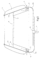
- Fig. 1 is schematized by dash-dotted lines the rear of a motor vehicle 1 with a left and a right-hand C-pillar. Between the C pillars 2 extends rear window 3 from a lower edge 4 to a rear edge of the roof 5. In front of the rear window 3 there is a parcel shelf 6 with a width continuous slot 7. Furthermore, inside the Motor vehicle 1 to recognize a window blind 8, which in Fig. 1 is shown in the extended position.
- a winding shaft 9 which is below the parcel shelf 6 is rotatably mounted, and a roller blind 11.
- the parcel shelf 6 To support the winding shaft 9 are on the bottom the parcel shelf 6 next to the slot 7 two bearing blocks 12 and 13 accommodate the journals 14 and 15, which axially from the protrude tubular winding shaft 9.
- spring motor 16 which is firmly connected at 17 to the winding shaft 9 and the other end of which is non-rotatably coupled to the journal 15 is.
- the bearing pin 15 is in turn rotatably in the Bearing block 13.
- the spring motor 16 forms part of the drive device of the rear window blind 8 and generates one Preload force in the sense of winding up the roller blind web 11 on the winding shaft 9.
- the roller blind 11 is on the Winding shaft 9, for example by means of a welt in known Way attached.
- the roller blind 11 consists of a trapezoidal Cut from a plastic film that is sufficient Shields sunlight.
- the roller blind 11 is left and right Side edge 18, 19 and an upper edge 21 and one attached to the winding shaft 9, not recognizable Edge, limited.
- the rear window roller blind 8 also includes a single one Guide rail 23 coming out of the roller blind slot 7 extends to the rear edge of the roof 5 and is fastened there; she runs next to the right C-pillar 2 approximately parallel to this. A second guide rail is in this embodiment unavailable.
- the Guide rail 23 consists of a C-shaped profile with a rear-engaging guide groove 24.
- the guide groove 24 opens at a slot 25 in the direction of the roller blind 11.
- a slide 26, consisting of, runs in the guide rail 23 from a cross section to the interior of the guide groove 24 attached base body 27, of which a strip-shaped Flange 28 extends through the slot 25 protrudes outwards.
- the basic body is 27 substantially cylindrical and the interior of the guide groove 24 of the guide rail 23 is also cylindrical.
- a bracket 29 is fastened to the flange 28 protrudes from the base body 27 substantially at right angles and in turn has the shape of a guide rail, in which the edge reinforcement bar 22 is longitudinally displaceable is recorded.
- the boom 29 is designed in such a way that the edge reinforcement bar 22 only one Has degree of freedom, namely in the direction parallel to the longitudinal extent of the boom 29. In the direction perpendicular to it she is tied up in the boom 29.
- a geared motor 31 which is actuated by an actuator 32 is coupled to the carriage 26.
- the actuator 32 is made of a rigid, linear element, for example a flexible metal or plastic wire 33, the soul of a Bowden cable or a shear-resistant, stranded wire strand formed.
- At least on the engine side End carries the actuator 32 on it Outer peripheral surface forming a screw or worm 34 Wire winding 35 which is immovable with the actuator 32 is connected.
- Actuators of this type are also available under the trade name "SU-flexwelle" and are used among other things in window regulators.
- the drive motor 31 is a permanently excited one DC motor, followed by a reduction gear 36 is. On an output shaft 37 of the transmission 36 sits a spur gear 38, its division with the Division of the screw or screw 34 matches.
- a guide 39 which is designed in such a way that they tangential the screw 34 of the actuator 32 leads to the output gear 38 and forces the Teeth of the spur gear 38 form-fit between the turns the screw 34 can engage.
- the actuator 32 connects the spur gear 38 geared with the carriage 26, and it is going out from the gear 36 or the guide 39 present there pressure-resistant in a casing 33a to the lower end of the guide rail 23 led. At this point, the actuator occurs 32 into the interior of the guide groove 24. The free end 41 of the actuator 32 is freely abutting at the lower end of the guide carriage 26.
- the rear window blinds When installed, the rear window blinds are open 8 only the guide rail 23 can be seen.
- the guide rail 23 runs next to the right edge of the window and largely disappears. Only the boom 29 would be seen in the slot 7 through which the Roller blind 11 is extended upwards.
- the roller blind 11 is under the action of the spring motor 16 wound on the winding shaft 9.
- the Carriage 26 is moved downward in the guide rail 23, so far until the boom 29 the aforementioned blind slot 7 fills out according to the length of the boom 29.
- the motor current increases, which is known in the Way of a monitoring circuit known per se is evaluated to be independent of the switch control to de-energize the drive motor 31 by the user.
- the arrangement also ensures, in a known manner, a restart of the motor current only for the reverse Allow direction of rotation.
- roller blind 11 is now fully extended and the boom 29 abuts the upper edge of the window frame 5 on.
- the blind 11 is in front of the entire window area spanned.
- a swinging of the boom 29 can be extended Avoid rear window roller blind 8 if according to the upper end position at the upper edge of the rear window 3 a hook-shaped pocket 42 is attached, the one down contains open groove 43.
- the groove 43 takes in the upper end position the boom 29 at a location by the Carriage 26 is spaced. Pendulum movements of the boom 53 about the longitudinal axis of the carriage 49 are thereby definitely excluded.
- the user sets to retract the rear window blind 8 the electric motor 31 via a corresponding switch operates in the opposite direction of rotation.
- the Spur gear 38 which meshes with the screw 34, pulls it Actuator 32 down from the guide rail 23 back, whereby the feed force acting against the carriage 49 subsides.
- the spring motor 16 is thereby in the Position corresponding to the retraction of the actuator 32 wind up the roller blind 11 again on the winding shaft 9.
- the lower end position of the actuator can in are queried in a similar manner to the upper end position, and be shut down accordingly.
- roller blind 11 is by the Effect of the spring motor 16 kept tense while the Position by the self-locking drive motor 31 is specified.
- the spring drive could 16 also swap places with the drive motor 31, in such a way that the drive motor 31 the winding shaft 9 positively drives while the actuator 32 acted upon by a compression spring or such is replaced.
- the slide 26 is biased in the unwinding direction, while the roller blind 11 against the action of the spring 16 the winding shaft 9 is wound up.
- FIG. 3 shows a rear window roller blind 8, which has a very similar structure to the rear window roller blind 8 according to Fig. 2.
- the main difference is in the edge reinforcement bar 22, which is from one down open U-shaped bar is formed.
- the bar 22 runs a roller 45 on the free end of the boom 29 is rotatably mounted.
- the rear window roller blind 8 has a single guide rail 23 on. 4 shows an embodiment in a highly schematic manner shown, in the rear window roller blind 8 free of guide rails is.
- the winding shaft is below the parcel shelf 6 9 rotatably mounted. It has an edge on it, as before described, the roller blind 11 attached, the cutting is designed approximately as shown in FIG. 1.
- the free ends of the actuators 32a and 32b are directly connected to the reinforcing bar 22.
- the actuators When extending, the actuators press the reinforcement bar 22 upwards and thereby wrap against the Effect of the spring motor in the winding shaft 9 the roller blind from the winding shaft 9.
- the part emerging from the slide guide blocks 46 actuators 32a and 32b are proportional stiff plastic or metal wire that on the one hand can follow the curved shape of the guide tubes 47, on the other hand is able to the reinforcing edge strip 22 to carry the roller blind 11 and against the rear window 3 to press.
- the free ends of the actuators 32a and 32b are permanently connected to the edge reinforcement bar 22.
- the function of the rear window roller blind 8 according to FIG. 4 is similar to the previously explained rear window blind 8 according to Figures 1 to 3. The only difference is in that the edge reinforcement bar 22 exclusively carried and guided by the actuators 32a and 32b becomes. It is understood that these actuators 32 run parallel to each other in the extended state.
- a or two receiving pockets 42 are provided, as shown in Fig. 2 shown and also described in connection with FIG. 2 were.
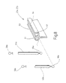
- FIGs 5 and 6 is an embodiment for a rear window blind 8 illustrates two guide rails 23a and 23b.
- the guide rails 23a and 23b have the same cross-sectional shape as this in connection is explained in detail with Fig. 3.
- the guide rail 23a is essentially straight the course of the right edge of the window frame, while the Guide rail 23b approximately parallel to the left rear window edge is aligned.
- the bow 52 is made up of two telescopically against each other movable bow pieces 53 and 54 together.
- the bow piece 53 is a cylindrical tube in which the Bow piece 54 is guided to be longitudinally displaceable. On his Free end, the bow piece 54 goes into a cylindrical Neck 55 over, which protrudes through the slot 25 and on carries a ball 56 at its free end.
- the ball 56 corresponds in diameter the diameter of the clear Interior of the guide groove 24 of the guide rail 23b.
- the left end of the bow piece 53 also goes in a neck 57 over which at its free end with a Ball 58 is provided.
- the ball 58 runs in the interior the guide rail 23a and is bound like the ball 56 therein, ie. it cannot emerge from the slot 25.
- the winding shaft 9 and its holder is again like designed in the previously described embodiments.
- the motor 31 in Gear set, which then the actuators 32a and 32b in the relevant guide rails 23a and 23b pushes up and thereby on the one hand with the ball 58 as well as with the ball 56 butt engagement.
- the bow 52 is always parallel to the winding shaft 9 aligned, pushed away from the winding shaft 9.
- the two guide rails have near the winding shaft 9 23a and 23b the greatest distance from each other, which is why the bow 52 is elongated accordingly and protrudes from the tubular pocket 51.
- Each the roller blind 11 approaches the extended end position, their top edge 21 comes closer to the guide rails 23a and 23b.
- the bow 52 is shortened corresponding. In the end position, the roller blind 11 fills the Space between the guide rails 23a and 23b completely and thus completely shadows the one in question Rear window 3 from.
- winding shaft 9 parallel to the lower window edge 7 shows an exemplary embodiment, in which the winding shaft 9 is aligned vertically and is therefore parallel to the C-pillar 2. It is about a version that is preferred for tailgates.
- the guide rail 23a extends parallel to the lower edge of the window 4, while the upper Guide cards 23b the course of the upper window edge 5 follows.
- the cross-sectional shape of the two guide rails 23a and 23b is the same, but differs from the profile of the guide rails 23 of the previous exemplary embodiments.
- the guides 23a and 23b contain two in Grooves 61 and 62 which extend through in the longitudinal direction and engage behind contains.
- the grooves 61 and 62 open through a continuous Groove slot 63 or 64 to the outside to the roller blind 11.
- Two bows 52a run in these grooves 61, 62 and 52b.
- the bars 52a and 52b have the same appearance as the bow 52 according to FIG. 6 for the rear window blind 8 according to Fig. 5. Therefore, a new explanation waived.
- the blind sheet 11 contains, in addition to the tubular one Pocket 51 on the front edge 21 still another tubular pocket 65 approximately at the middle of the extension length the roller blind 11.
- the pocket 65 runs parallel to the winding shaft 9 the receiving pocket 75.
- the pockets 65 takes the bow 52b and the pockets 51 the bow 52a on.
- roller blind 11 To extend the roller blind 11 are for the upper guide rail 23a and the lower guide rail 23b separate Actuators available, which are not in the figure are shown.
- the actuators run in those Grooves in which the bow 52a of the leading edge 21 is guided and is further from the winding shaft 9 than that each other groove 62.
- the drive motor is used to extend the roller blind 11 started and the actuators in the groove 61st of the two guide rails 23a and 23b 85 in the direction of the left side of the vehicle is pushed forward.
- the balls the bow 52a taken along and over the front edge 21 of the roller blind 11.
- roller blind 11 is pulled out Condition also supported or guided in the middle and can swing less. On the other hand, it hinders the support serving bows 52b not winding.
- the designer decides at his own discretion and depends above all on the available ones Boundary conditions such as window size, window proportions and Window geometry, space in the rear interior trim or below the parcel shelf and the like.
- Boundary conditions such as window size, window proportions and Window geometry, space in the rear interior trim or below the parcel shelf and the like.
- the rear window blinds shown are by no means limited to saloon sedan applications is.
- the rear window roller blind according to the invention can be without implement another by putting it behind the fairing the C-pillar is installed.
- selected combinations of features are shown and explained.
- a rear window roller blind for motor vehicles has one Winding shaft, which is preferably rotatable under the parcel shelf is stored. Through a slot in the parcel shelf pull out a roller blind that covers the window. For this purpose, grips the edge of the roller blind, the longest way, an actuator.
- the actuator is a linear element that ever is either tensile or compression-resistant after execution.
- the Roller blind itself can at least next to the window with the help a guide rail or one or two pressure or rigid actuators are held open.
Landscapes
- Engineering & Computer Science (AREA)
- Mechanical Engineering (AREA)
- Operating, Guiding And Securing Of Roll- Type Closing Members (AREA)
Abstract
Description
Claims (32)
- Heckfensterrollo (8) für Kraftfahrzeuge, das von einer unteren etwa horizontal verlaufenden Fensterrahmenkante (4) sowie zwei seitlichen etwa senkrecht verlaufenden Fensterrahmenkanten (2) und einer oberen horizontal verlaufenden Fensterrahmenkante (5) begrenzt ist,mit einer drehbar gelagerten Wickelwelle (9),mit einer Rollobahn (11), deren Zuschnitt zumindest in einem Abschnitt ihrer Längserstreckung zumindest angenähert der Form des Heckfensters (3) entspricht und die einen umlaufenden Rollobahnrand aufweist, der einen Abschnitt bildet, der an der Wickelwelle (9) befestigt ist, sowie einen Abschnitt (21), der von der Wickelwelle (9) abliegt,mit wenigstens einem Betätigungsmittel (23), das mit dem von der Wickelwelle (9) abliegenden Abschnitt (21) des Rollobahnrands verbunden ist, undmit Antriebsmitteln (16,31) zum kraftbetätigten Einund Ausfahren der Rollobahn.
- Heckfensterrollo nach Anspruch 1, dadurch gekennzeichnet, dass die Wickelwelle (9) etwa seitlich neben dem Heckfenster (3) verlaufend angeordnet ist.
- Heckfensterrollo nach Anspruch 1, dadurch gekennzeichnet, dass die Wickelwelle (9) etwa horizontal verlaufend unterhalb des Heckfensters (3) angeordnet ist.
- Heckfensterrollo nach Anspruch 1, dadurch gekennzeichnet, dass wenigstens eine Führungsschiene (23) vorgesehen ist.
- Heckfensterrollo nach Anspruch 1, dadurch gekennzeichnet, dass zwei Führungsschienen (23a,23b) vorgesehen sind.
- Heckfensterrollo nach Anspruch 4, dadurch gekennzeichnet, dass die wenigstens eine Führungsschiene (23) horizontal verlaufend angeordnet ist.
- Heckfensterrollo nach Anspruch 4, dadurch gekennzeichnet, dass die wenigstens eine Führungsschiene (23) parallel zu der unteren Fensterrahmenkante (4) verläuft.
- Heckfensterrollo nach Anspruch 1, dadurch gekennzeichnet, dass die wenigstens eine Führungsschiene (23) seitlich neben dem Heckfenster (3) verlaufend angeordnet ist.
- Heckfensterrollo nach Anspruch 1, dadurch gekennzeichnet, dass die wenigstens eine Führungsschiene (23) parallel zu der seitlichen Fensterrahmenkante (2) verläuft.
- Heckfensterrollo nach Anspruch 1, dadurch gekennzeichnet, dass es frei von Führungsschienen ist.
- Heckfensterrollo nach Anspruch 1, dadurch gekennzeichnet, dass der Rollobahnrand zumindest in einem von der Wickelwelle (9) abliegenden Abschnitt (21) eine Randverstärkung (22,52) aufweist.
- Heckfensterrollo nach Anspruch 11, dadurch gekennzeichnet, dass die Randverstärkung (22) flexibel ist.
- Heckfensterrollo nach Anspruch 11, dadurch gekennzeichnet, dass ein Abschnitt der Randverstärkung (22) steif ist.
- Heckfensterrollo nach Anspruch 11, dadurch gekennzeichnet, dass zumindest ein Abschnitt der Randverstärkung (22) als Zugstange dient.
- Heckfensterrollo nach Anspruch 4, dadurch gekennzeichnet, dass die Rollobahn (11) mit wenigstens einem Spriegel (52) versehen ist, der in der wenigstens einen Führungsschiene (23) endseitig geführt ist.
- Heckfensterrollo nach Anspruch 16, dadurch gekennzeichnet, dass der wenigstens eine Spriegel (52) beidends in Führungsschienen (23a,23b) geführt ist.
- Heckfensterrollo nach Anspruch 16, dadurch gekennzeichnet, dass der Spriegel (52) teleskopisch längenverstellbar ist.
- Heckfensterrollo nach Anspruch 4, dadurch gekennzeichnet, dass in der wenigstens einen Führungsschiene (23) ein Schlitten (26) geführt ist, an dem ein Ausleger (29) befestigt ist, mit dem ein Abschnitt (21) des Rollobahnrands verbunden ist.
- Heckfensterrollo nach Anspruch 19, dadurch gekennzeichnet, dass der Abschnitt (21) der Rollobahnrands mit dem Ausleger (29) längsverschieblich verbunden ist.
- Heckfensterrollo nach Anspruch 1, dadurch gekennzeichnet, dass zu dem Betätigungsmittel (32) wenigstens ein linienförmiges Druckglied (33) gehört, das vorzugsweise in einer Hülle (33a) drucksteif geführt ist.
- Heckfensterrollo nach Anspruch 1, dadurch gekennzeichnet, dass zu dem Betätigungsmittel (32) wenigstens eine biegesteife Stange (33) gehört, deren freies Ende mit dem Rollobahnrand (21) verbunden ist und die in einer ortsfesten Führungseinrichtung (46) längsverschieblich geführt ist, wobei die Bewegungsrichtung im Wesentlichen rechtwinkelig zu der Achse der Wickelwelle (9) verläuft.
- Heckfensterrollo nach den Ansprüchen 21 und 22, dadurch gekennzeichnet, dass die wenigstens eine Stange (33) mit dem linienförmigen Druckglied (33) gekoppelt ist, bzw. durch diese gebildet ist.
- Heckfensterrollo nach den Ansprüchen 19 und 21, dadurch gekennzeichnet, dass das linienförmige Druckglied (33) mit dem Schlitten (26) gekoppelt ist.
- Heckfensterrollo nach den Ansprüchen 16 und 21, dadurch gekennzeichnet, dass das linienförmige Druckglied (33) mit dem Spriegel (52) gekoppelt ist.
- Heckfensterrollo nach Anspruch 21, dadurch gekennzeichnet, dass das linienförmige Druckglied (33) zumindest an einem Ende mit einer Verzahnung (34) versehen ist, mittels derer das linienförmige Druckglied (57) formschlüssig mit einem Zahnrad (64) eines Antriebsmotors (55) gekuppelt ist.
- Heckfensterrollo nach Anspruch 1, dadurch gekennzeichnet, dass zu den Betätigungsmitteln (32) wenigstens ein Seil gehört.
- Heckfensterrollo nach Anspruch 1, dadurch gekennzeichnet, dass zu den Antriebsmitteln (16,31) eine Feder (16) gehört.
- Heckfensterrollo nach Anspruch 28, dadurch gekennzeichnet, dass die Feder (16) in Gestalt eines Federmotors mit der Wickelwelle (9) gekuppelt ist und die Wickelwelle (9) in Aufrollrichtung der Rollobahn (11) vorspannt.
- Heckfensterrollo nach Anspruch 28, dadurch gekennzeichnet, dass die Feder (16) über das Betätigungsmittel (32) mit der Rollobahn (11) verbunden ist und die Rollobahn (11) im Sinne des Abwickelns von der Wickelwelle (9) vorspannt.
- Heckfensterrollo nach Anspruch 1, dadurch gekennzeichnet, dass zu den Antriebsmitteln (16,31) wenigstens ein Getriebemotor (31) gehört.
- Heckfensterrollo nach Anspruch 11, dadurch gekennzeichnet, dass der Getriebemotor (31 mit der Wickelwelle (9) gekoppelt ist.
- Heckfensterrollo nach Anspruch 11, dadurch gekennzeichnet, dass der Getriebemotor (31) über das Betätigungsmittel (32) mit der Rollobahn (11) gekoppelt ist.
Applications Claiming Priority (2)
| Application Number | Priority Date | Filing Date | Title |
|---|---|---|---|
| DE10005951 | 2000-02-09 | ||
| DE10005951A DE10005951A1 (de) | 2000-02-09 | 2000-02-09 | Heckfensterrollo |
Publications (4)
| Publication Number | Publication Date |
|---|---|
| EP1123825A2 true EP1123825A2 (de) | 2001-08-16 |
| EP1123825A3 EP1123825A3 (de) | 2002-12-18 |
| EP1123825B1 EP1123825B1 (de) | 2004-11-24 |
| EP1123825B9 EP1123825B9 (de) | 2005-06-29 |
Family
ID=7630489
Family Applications (1)
| Application Number | Title | Priority Date | Filing Date |
|---|---|---|---|
| EP01103017A Expired - Lifetime EP1123825B9 (de) | 2000-02-09 | 2001-02-08 | Heckfensterrollo |
Country Status (5)
| Country | Link |
|---|---|
| US (1) | US20010017194A1 (de) |
| EP (1) | EP1123825B9 (de) |
| JP (1) | JP2001241277A (de) |
| KR (1) | KR20010078789A (de) |
| DE (2) | DE10005951A1 (de) |
Cited By (6)
| Publication number | Priority date | Publication date | Assignee | Title |
|---|---|---|---|---|
| FR2841185A1 (fr) * | 2002-06-25 | 2003-12-26 | Wagon Automotive Snc | Store a enrouleur a entrainement par cable, et vehicule automobile correspondant |
| EP1447251A1 (de) * | 2003-02-13 | 2004-08-18 | Wagon Sas | Sonnenschutzvorrichtung mit Dämpfung am Bewegungsende |
| EP1621380A3 (de) * | 2004-07-29 | 2008-09-10 | BOS GmbH & Co. KG | Gekrümmtes Fensterrollo mit innen liegendem Federwiderlager |
| EP2979908A1 (de) * | 2014-08-01 | 2016-02-03 | BOS GmbH & Co. KG | Beschattungsvorrichtung für ein transparentes flächenteil eines kraftfahrzeugs |
| US9764624B2 (en) | 2014-08-01 | 2017-09-19 | Bos Gmbh & Co. Kg | Shading device for a transparent surface part of a motor vehicle |
| US9914342B2 (en) | 2014-08-01 | 2018-03-13 | Bos Gmbh & Co. Kg | Shading device for a transparent surface part of a motor vehicle |
Families Citing this family (34)
| Publication number | Priority date | Publication date | Assignee | Title |
|---|---|---|---|---|
| DE10005970A1 (de) * | 2000-02-09 | 2001-08-23 | Bos Gmbh | Seitenfensterrollo |
| DE10057763C2 (de) * | 2000-11-22 | 2002-10-24 | Bos Gmbh | Doppelrollo mit vereinfachtem Antrieb |
| DE10057760B4 (de) * | 2000-11-22 | 2004-08-12 | Bos Gmbh & Co. Kg | Fensterrollo mit Zentriereinrichtung für den Zugstab |
| DE10057762A1 (de) * | 2000-11-22 | 2002-06-06 | Bos Gmbh | Fensterrollo mit Ausgleich gegen Verzug |
| JP3662847B2 (ja) * | 2000-12-28 | 2005-06-22 | 松下電工株式会社 | ブラインド装置 |
| DE10113616C1 (de) * | 2001-03-20 | 2002-10-10 | Butz Peter Verwaltung | Laderaumabdeckung für Kraftwagen, wie für Kombinations-Personenkraftwagen od. dgl. |
| DE10113621C1 (de) * | 2001-03-20 | 2002-10-10 | Butz Peter Verwaltung | Laderaumabdeckung für Kraftwagen, wie für Kombinations-Personenkraftwagen od. dgl. |
| WO2002080172A1 (fr) * | 2001-03-30 | 2002-10-10 | Sony Corporation | Appareil d'enregistrement ou de reproduction de support d'enregistrement et procede de commande de sortie de donnees |
| DE10151872B4 (de) * | 2001-10-24 | 2007-10-04 | Bos Gmbh & Co. Kg | Geteiltes Fensterrollo für Kraftfahrzeuge |
| DE10245901A1 (de) * | 2002-09-30 | 2004-04-08 | Schwab Technik Gmbh | Rolloanordnung für Fahrzeugscheiben |
| DE10248591B4 (de) * | 2002-10-17 | 2006-04-20 | Bos Gmbh & Co. Kg | Fensterrollo mit Deckel auf dem Auszugschlitz |
| DE10256599A1 (de) * | 2002-12-04 | 2004-06-17 | Arvinmeritor Gmbh | Rollosystem, insbesondere für ein Kraftfahrzeug |
| FR2851202B1 (fr) * | 2003-02-13 | 2005-05-06 | Wagon Automotive Snc | Rail de guidage pre-equipe pour store de vehicule automobile, ensemble de store, procede d'assemblage et de montage et vehicules automobile correspondants |
| DE10322709B3 (de) * | 2003-05-20 | 2005-03-17 | Webasto Ag | Sonnenschutzrolloanordnung für ein Fahrzeugdach sowie Fahrzeugdach mit einer solchen Sonnenschutzrolloanordnung |
| DE10334695A1 (de) * | 2003-07-25 | 2005-02-10 | Brose Fahrzeugteile Gmbh & Co. Kg | Rollo-Anordnung für ein Fenster eines Kraftfahrzeugs |
| DE10338722A1 (de) * | 2003-08-22 | 2005-03-17 | Opel Eisenach Gmbh | Beschattungssystem für eine Panoramascheibe |
| US6983786B2 (en) * | 2003-09-24 | 2006-01-10 | Ing-Wen Chen | Height-adjustable car curtain |
| DE10353778A1 (de) * | 2003-11-18 | 2005-06-23 | Bos Gmbh & Co. Kg | Fahrzeugrollo mit vereinfachter Ankoppelung der Führungsschienen |
| DE10356911B3 (de) * | 2003-12-02 | 2005-01-20 | Bos Gmbh & Co. Kg | Laderaumschutzvorrichtung für ein Kraftfahrzeug |
| DE10357028A1 (de) * | 2003-12-03 | 2005-06-30 | Volkswagen Ag | Verdunkelungseinrichtung für eine Fensterscheibe eines Fahrzeuges |
| DE102004058296A1 (de) * | 2004-12-02 | 2006-06-08 | Bos Gmbh & Co. Kg | Rolloanordnung mit verdeckter Rastung |
| JP4560442B2 (ja) * | 2005-05-23 | 2010-10-13 | トヨタ紡織株式会社 | サンシェード開閉装置 |
| DE102005029559B4 (de) * | 2005-06-23 | 2007-05-03 | Bos Gmbh & Co. Kg | Heckfensterrollo mit vollständiger Schlitzabdeckung durch das Auszugsprofil |
| DE102005030707A1 (de) * | 2005-06-29 | 2007-01-04 | Bos Gmbh & Co. Kg | Fensterrollo für Kraftfahrzeuge mit formschlüssigem Anschlag auf dem Betätigungsglied |
| DE102005036318A1 (de) * | 2005-07-29 | 2007-02-01 | Bos Gmbh & Co. Kg | Fensterrollo mit glatten Schubgliedern |
| EP1787864B1 (de) * | 2005-11-22 | 2009-03-25 | Mazda Motor Corporation | Hintere Struktur eines Kraftfahrzeugs |
| DE102006008160A1 (de) * | 2006-02-22 | 2007-08-30 | Bos Gmbh & Co. Kg | Rollo mit Zentrierung durch Anschläge |
| KR100828600B1 (ko) | 2006-08-21 | 2008-05-09 | 현대자동차주식회사 | 차량용 선바이저의 시야 확보 장치 |
| JP5310405B2 (ja) * | 2009-09-03 | 2013-10-09 | トヨタ紡織株式会社 | サンシェード装置 |
| JP5528790B2 (ja) * | 2009-12-28 | 2014-06-25 | 芦森工業株式会社 | 車両用ウインドウシェード装置 |
| JP5646934B2 (ja) | 2010-09-24 | 2014-12-24 | 芦森工業株式会社 | サンシェード装置 |
| US20120186759A1 (en) * | 2011-01-25 | 2012-07-26 | Paul Lin | Sunshade Assembly for a Side Window of a Vehicle |
| DE102011006237A1 (de) * | 2011-03-28 | 2012-10-04 | Bos Gmbh & Co. Kg | Rollosystem für ein Kraftfahrzueg |
| KR101602280B1 (ko) * | 2015-02-23 | 2016-03-11 | 크레노바멀티미디어 주식회사 | 리눅스 운영체계 기반의 디지털 셋톱박스 |
Citations (1)
| Publication number | Priority date | Publication date | Assignee | Title |
|---|---|---|---|---|
| EP0240747A2 (de) | 1986-04-11 | 1987-10-14 | Baumeister & Ostler GmbH & Co. | Führungsloses Fensterrollo, insbesondere für Kraftfahrzeuge |
Family Cites Families (5)
| Publication number | Priority date | Publication date | Assignee | Title |
|---|---|---|---|---|
| DE3415930A1 (de) * | 1984-04-28 | 1985-10-31 | Baumeister & Ostler, 7307 Aichwald | Kraftfahrzeugfensterrollo |
| DE3608927A1 (de) * | 1986-03-18 | 1987-09-24 | Ieper Ind Nv | Blendschutzeinrichtung fuer ein fahrzeug |
| JPH0478628A (ja) * | 1990-05-23 | 1992-03-12 | Nhk Spring Co Ltd | シート状物巻取装置 |
| US5860466A (en) * | 1996-02-02 | 1999-01-19 | Kao; Nien Tsu Tim | Windshield shelter |
| US5752560A (en) * | 1997-03-21 | 1998-05-19 | Cherng; Bing Jye | Electric sunshield for automobiles |
-
2000
- 2000-02-09 DE DE10005951A patent/DE10005951A1/de not_active Withdrawn
-
2001
- 2001-01-26 JP JP2001018041A patent/JP2001241277A/ja active Pending
- 2001-02-08 DE DE50104571T patent/DE50104571D1/de not_active Expired - Lifetime
- 2001-02-08 EP EP01103017A patent/EP1123825B9/de not_active Expired - Lifetime
- 2001-02-08 US US09/779,765 patent/US20010017194A1/en not_active Abandoned
- 2001-02-08 KR KR1020010006083A patent/KR20010078789A/ko not_active Application Discontinuation
Patent Citations (1)
| Publication number | Priority date | Publication date | Assignee | Title |
|---|---|---|---|---|
| EP0240747A2 (de) | 1986-04-11 | 1987-10-14 | Baumeister & Ostler GmbH & Co. | Führungsloses Fensterrollo, insbesondere für Kraftfahrzeuge |
Cited By (8)
| Publication number | Priority date | Publication date | Assignee | Title |
|---|---|---|---|---|
| FR2841185A1 (fr) * | 2002-06-25 | 2003-12-26 | Wagon Automotive Snc | Store a enrouleur a entrainement par cable, et vehicule automobile correspondant |
| EP1375221A1 (de) * | 2002-06-25 | 2004-01-02 | Wagon Automotive Snc | Kabelangetriebenes Fensterrollo für Kraftfahrzeuge |
| EP1447251A1 (de) * | 2003-02-13 | 2004-08-18 | Wagon Sas | Sonnenschutzvorrichtung mit Dämpfung am Bewegungsende |
| FR2851199A1 (fr) * | 2003-02-13 | 2004-08-20 | Wagon Automotive Snc | Store pour vehicule automobile a ralentisseur en fin de course, et vehicule correspondant. |
| EP1621380A3 (de) * | 2004-07-29 | 2008-09-10 | BOS GmbH & Co. KG | Gekrümmtes Fensterrollo mit innen liegendem Federwiderlager |
| EP2979908A1 (de) * | 2014-08-01 | 2016-02-03 | BOS GmbH & Co. KG | Beschattungsvorrichtung für ein transparentes flächenteil eines kraftfahrzeugs |
| US9764624B2 (en) | 2014-08-01 | 2017-09-19 | Bos Gmbh & Co. Kg | Shading device for a transparent surface part of a motor vehicle |
| US9914342B2 (en) | 2014-08-01 | 2018-03-13 | Bos Gmbh & Co. Kg | Shading device for a transparent surface part of a motor vehicle |
Also Published As
| Publication number | Publication date |
|---|---|
| EP1123825A3 (de) | 2002-12-18 |
| EP1123825B1 (de) | 2004-11-24 |
| US20010017194A1 (en) | 2001-08-30 |
| KR20010078789A (ko) | 2001-08-21 |
| JP2001241277A (ja) | 2001-09-04 |
| DE50104571D1 (de) | 2004-12-30 |
| DE10005951A1 (de) | 2001-08-16 |
| EP1123825B9 (de) | 2005-06-29 |
Similar Documents
| Publication | Publication Date | Title |
|---|---|---|
| EP1123825A2 (de) | Heckfensterrollo | |
| EP1123824B1 (de) | Seitenfensterrollo | |
| EP1182066B1 (de) | Fahrzeug mit Sonnenschutzrollo im Dach | |
| EP1886853B1 (de) | Fensterrollo mit Antrieb über den Fensterheber | |
| EP1306251B1 (de) | Geteiltes Fensterrollo für Kraftfahrzeuge | |
| EP1211109B1 (de) | Fensterrollo mit Zentriereinrichtung für den Zugstab | |
| EP1479564B1 (de) | Schutzvorrichtung für einen Innenraum eines Kraftfahrzeuges | |
| EP2039547B1 (de) | Seitenfensterrollo mit Einlaufhilfe | |
| DE10228028B3 (de) | Heckscheibenrollo mit Hubkassette | |
| EP1533158B1 (de) | Seitenfensterrollosystem mit Konturteil | |
| EP1724137B1 (de) | Fensterrollo mit längsverstellbarer Wickelwelle | |
| DE102005055625B4 (de) | Laderaumabdeckung für ein Fahrzeug | |
| EP1905626A1 (de) | Rollantrieb mit Federmotor und verminderter Antriebskraft | |
| EP1029746A2 (de) | Überroll-Schutzsystem für Kraftfahrzeuge | |
| DE102007012281A1 (de) | Automatisch betätigbares Seitenfensterrollo | |
| DE19825353A1 (de) | Laderaumabdeckung für Kraftfahrzeuge, insbesondere für Kombinations-Personenkraftwagen od. dgl. | |
| DE202004014652U1 (de) | Fahrzeugtür mit einem Fensterheber | |
| DE2204623A1 (de) | Kraftfahrzeug mit mechanisch betaetigbarem dreipunkt-sicherheitsgurt | |
| EP1738942A2 (de) | Fensterrollo für Kraftfahrzeuge mit formschlüssigem Anschlag auf dem Betätigungsglied | |
| EP3478521B1 (de) | Beschattungsvorrichtung für eine scheibe eines kraftfahrzeugs | |
| EP2006133A2 (de) | Elektrisches Seitenfensterrollo | |
| DE102007004665B4 (de) | Fensterrollo mit Antrieb über den Fensterhebermotor | |
| DE202007008178U1 (de) | Seitenfensterrollo | |
| EP2562019B1 (de) | Dachfenstereinheit für ein Kraftfahrzeug und Kraftfahrzeug mit solch einer Einheit | |
| DE102005030962A1 (de) | Rollo mit elektrischem Einklemmschutz |
Legal Events
| Date | Code | Title | Description |
|---|---|---|---|
| PUAI | Public reference made under article 153(3) epc to a published international application that has entered the european phase |
Free format text: ORIGINAL CODE: 0009012 |
|
| AK | Designated contracting states |
Kind code of ref document: A2 Designated state(s): AT BE CH CY DE DK ES FI FR GB GR IE IT LI LU MC NL PT SE TR |
|
| AX | Request for extension of the european patent |
Free format text: AL;LT;LV;MK;RO;SI |
|
| PUAL | Search report despatched |
Free format text: ORIGINAL CODE: 0009013 |
|
| AK | Designated contracting states |
Kind code of ref document: A3 Designated state(s): AT BE CH CY DE DK ES FI FR GB GR IE IT LI LU MC NL PT SE TR |
|
| AX | Request for extension of the european patent |
Free format text: AL;LT;LV;MK;RO;SI |
|
| 17P | Request for examination filed |
Effective date: 20030228 |
|
| 17Q | First examination report despatched |
Effective date: 20030429 |
|
| AKX | Designation fees paid |
Designated state(s): DE FR GB IT |
|
| GRAP | Despatch of communication of intention to grant a patent |
Free format text: ORIGINAL CODE: EPIDOSNIGR1 |
|
| GRAS | Grant fee paid |
Free format text: ORIGINAL CODE: EPIDOSNIGR3 |
|
| GRAA | (expected) grant |
Free format text: ORIGINAL CODE: 0009210 |
|
| AK | Designated contracting states |
Kind code of ref document: B1 Designated state(s): DE FR GB IT |
|
| REG | Reference to a national code |
Ref country code: GB Ref legal event code: FG4D Free format text: NOT ENGLISH |
|
| RAP2 | Party data changed (patent owner data changed or rights of a patent transferred) |
Owner name: BOS GMBH & CO. KG |
|
| REF | Corresponds to: |
Ref document number: 50104571 Country of ref document: DE Date of ref document: 20041230 Kind code of ref document: P |
|
| REG | Reference to a national code |
Ref country code: IE Ref legal event code: FG4D Free format text: GERMAN |
|
| GBT | Gb: translation of ep patent filed (gb section 77(6)(a)/1977) |
Effective date: 20050412 |
|
| REG | Reference to a national code |
Ref country code: IE Ref legal event code: FD4D |
|
| ET | Fr: translation filed | ||
| PLBE | No opposition filed within time limit |
Free format text: ORIGINAL CODE: 0009261 |
|
| STAA | Information on the status of an ep patent application or granted ep patent |
Free format text: STATUS: NO OPPOSITION FILED WITHIN TIME LIMIT |
|
| 26N | No opposition filed |
Effective date: 20050825 |
|
| PGFP | Annual fee paid to national office [announced via postgrant information from national office to epo] |
Ref country code: GB Payment date: 20080220 Year of fee payment: 8 Ref country code: IT Payment date: 20080223 Year of fee payment: 8 |
|
| GBPC | Gb: european patent ceased through non-payment of renewal fee |
Effective date: 20090208 |
|
| PG25 | Lapsed in a contracting state [announced via postgrant information from national office to epo] |
Ref country code: GB Free format text: LAPSE BECAUSE OF NON-PAYMENT OF DUE FEES Effective date: 20090208 |
|
| PG25 | Lapsed in a contracting state [announced via postgrant information from national office to epo] |
Ref country code: IT Free format text: LAPSE BECAUSE OF NON-PAYMENT OF DUE FEES Effective date: 20090208 |
|
| PGFP | Annual fee paid to national office [announced via postgrant information from national office to epo] |
Ref country code: FR Payment date: 20140219 Year of fee payment: 14 |
|
| REG | Reference to a national code |
Ref country code: FR Ref legal event code: ST Effective date: 20151030 |
|
| PG25 | Lapsed in a contracting state [announced via postgrant information from national office to epo] |
Ref country code: FR Free format text: LAPSE BECAUSE OF NON-PAYMENT OF DUE FEES Effective date: 20150302 |
|
| PGFP | Annual fee paid to national office [announced via postgrant information from national office to epo] |
Ref country code: DE Payment date: 20160226 Year of fee payment: 16 |
|
| REG | Reference to a national code |
Ref country code: DE Ref legal event code: R119 Ref document number: 50104571 Country of ref document: DE |
|
| PG25 | Lapsed in a contracting state [announced via postgrant information from national office to epo] |
Ref country code: DE Free format text: LAPSE BECAUSE OF NON-PAYMENT OF DUE FEES Effective date: 20170901 |