EP1123761B1 - Système de transport horizontal - Google Patents
Système de transport horizontal Download PDFInfo
- Publication number
- EP1123761B1 EP1123761B1 EP00128237A EP00128237A EP1123761B1 EP 1123761 B1 EP1123761 B1 EP 1123761B1 EP 00128237 A EP00128237 A EP 00128237A EP 00128237 A EP00128237 A EP 00128237A EP 1123761 B1 EP1123761 B1 EP 1123761B1
- Authority
- EP
- European Patent Office
- Prior art keywords
- drive
- movement
- slide
- crossmember
- toothed
- Prior art date
- Legal status (The legal status is an assumption and is not a legal conclusion. Google has not performed a legal analysis and makes no representation as to the accuracy of the status listed.)
- Expired - Lifetime
Links
- 230000032258 transport Effects 0.000 claims description 54
- 230000033001 locomotion Effects 0.000 claims description 53
- 230000005540 biological transmission Effects 0.000 claims description 9
- 238000012545 processing Methods 0.000 claims description 5
- 238000012546 transfer Methods 0.000 description 27
- 230000008859 change Effects 0.000 description 6
- 230000008901 benefit Effects 0.000 description 4
- 238000000034 method Methods 0.000 description 4
- 230000006978 adaptation Effects 0.000 description 3
- 230000008569 process Effects 0.000 description 3
- 230000009467 reduction Effects 0.000 description 3
- 238000013461 design Methods 0.000 description 2
- 238000005265 energy consumption Methods 0.000 description 2
- 230000002349 favourable effect Effects 0.000 description 2
- 241000252254 Catostomidae Species 0.000 description 1
- 230000001133 acceleration Effects 0.000 description 1
- 230000002146 bilateral effect Effects 0.000 description 1
- 150000001875 compounds Chemical class 0.000 description 1
- 238000010276 construction Methods 0.000 description 1
- 230000008878 coupling Effects 0.000 description 1
- 238000010168 coupling process Methods 0.000 description 1
- 238000005859 coupling reaction Methods 0.000 description 1
- 230000001419 dependent effect Effects 0.000 description 1
- 238000011161 development Methods 0.000 description 1
- 230000018109 developmental process Effects 0.000 description 1
- 238000010586 diagram Methods 0.000 description 1
- 230000001105 regulatory effect Effects 0.000 description 1
- 238000005096 rolling process Methods 0.000 description 1
- 230000001360 synchronised effect Effects 0.000 description 1
Images


Classifications
-
- B—PERFORMING OPERATIONS; TRANSPORTING
- B21—MECHANICAL METAL-WORKING WITHOUT ESSENTIALLY REMOVING MATERIAL; PUNCHING METAL
- B21D—WORKING OR PROCESSING OF SHEET METAL OR METAL TUBES, RODS OR PROFILES WITHOUT ESSENTIALLY REMOVING MATERIAL; PUNCHING METAL
- B21D43/00—Feeding, positioning or storing devices combined with, or arranged in, or specially adapted for use in connection with, apparatus for working or processing sheet metal, metal tubes or metal profiles; Associations therewith of cutting devices
- B21D43/02—Advancing work in relation to the stroke of the die or tool
- B21D43/04—Advancing work in relation to the stroke of the die or tool by means in mechanical engagement with the work
- B21D43/05—Advancing work in relation to the stroke of the die or tool by means in mechanical engagement with the work specially adapted for multi-stage presses
Definitions
- the invention relates to a transport device for Transporting workpieces in a press line or large step press after the generic term of Claim 1.
- press line or large step press are transfer devices for the transport of workpieces in the processing stages provided.
- Earlier transport systems saw by cam drive controlled longitudinal and Strokes, as well as any transverse movements of the Transport devices that from the main drive of a press were derived and thus forcibly synchronized to Plunger movement proceeded (EP 0 210 745, Fig. 4).
- EP 0 672 480 B1 or EP 0 693 334 A1 the transport process takes place between individual Processing stations individually by individual Transport equipment, in particular a universal Agility of workpiece transport between individual Enable processing levels.
- a transport device becomes, in which in the longitudinal extension over the entire Press length, above the parts transport level, in height-adjustable slide mounted mounting rails are provided. These rails are used for storage and as the carriageway of transport vehicles, each with its own, independent drive systems.
- the respective dolly can be separated in several Degrees of freedom.
- Shooting for crossbeams are integrated in the trolleys.
- the crossbeams are with holding elements, such as suckers, pliers or magnets for Workpiece holder and transport provided.
- the crossbeams are each two lateral Dolly held and moved. It will thus become one Transport system disclosed at the common horizontal arranged support rails Dolly with self-propelled can be moved independently of each other.
- the to be moved Masses are relatively large, since the drives are not stationary are, but go along.
- Document GB-A-2 086 285 discloses a device for Transporting workpieces according to the preamble of the claim 1 become known.
- this device are two provided independently of each other drive motors, the drive of the servomotors a lever adjustment of Transport arm can perform in any movement.
- the Drive motors each act on their own Lever system.
- EP-A-0 658 403 discloses a transport device a multi-station press has become known, the one Lever system with corresponding drives for implementation has a horizontal pivoting movement.
- the invention is based on the idea that in the DE 199 11 796 described so drive to develop that also a horizontal cultivation is possible. This horizontal cultivation is z. B. then required if the transport step due to the Geometry of the workpieces becomes so great that a vertical Transport system an increase in the press height required. A stationary attachment of 2 drives ensures the significant reduction in transport involved masses. These drives are independent adjustable in speed and direction of rotation. In Overlay active compound with motion transfer agent the movements and any programmable travel curve in a level can be executed.
- a movement transmitting means may preferably Sprockets and racks are used.
- the system consists of dolly the each have their own drive systems and guides.
- the Number of trolleys depends on the number of trolleys Forming stages of the press. It can also be before the first Forming stage required board depositors also with be executed this drive system.
- a significant advantage of the proposed transport system is the easy adaptation to the required transport or Stride lengths even with very different Much of presses. Only by changing the length of Guide rails and motion transfer means can the Adaptation to the required transport step done. Consequently this is by reducing the design effort a modular, cost-effective system.
- each Transport unit may vary depending on the particular Tamping or Störkantenlage optimally operated time, to achieve high cycle rates, with low transport times.
- Another advantage is that each system has its own Step lengths and speeds, i. E. the Acceleration values are dependent on the respective Workpiece stiffness selectable.
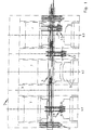
- FIG. 1 are processing or forming stages of a Major step press 1 shown.
- the invention Transfer system 2 extends over the entire press length seen in the transport direction. Drive and guides are in horizontal arrangement with attachment points on Press stands 3 mounted.
- a Adjustment device 4 for central or groupwise Method of the transfer system 2 in the vertical direction.
- These Function may be required for tool change, for Avoiding a collision between the tool 5 and the Transfer system 2. It is therefore a pure Rüstachse.
- As a further setup function is a height adjustment the transfer system 2 possible.
- different Transport positions are visible in the illustration. While in the forming stage 6.1 a workpiece removal by Transfer system 2.1 takes place next to the forming stage 6.2 the transfer system 2.2 in parking position.
- the Transfer system 2.3 is in forming stage 6.3 in one Transport function with swiveled part holder. Well recognizable is the different position of the plunger 7, i.e. due to the flexibility of the transfer systems 2.1 - 2.3
- the press can be operated with phase-shifted plungers become. The max. Load on the press due to the forming forces is thus significantly reduced and thus the torque on the drive shaft.
- FIG. 2 shows that Drive concept of a transport system.
- Drives A1, A2 put gears 8, 9 in rotation or keep them in Rest. These gears 8, 9 act on racks 10, 11 and thus influence their horizontal position.
- the racks 10, 11 are in operative connection with the gear 12.
- Rack 13 is replaced by gear 12th powered and performs a vertical movement.
- At the Anlenk Vietnamese 14 of the rack 13 are the actual Holder and holder for workpiece transport attached, as described in more detail in the following figures.
- the proposed arrangement can thus by regulating the Drives A1, A2 the point of articulation 14 any point in reach an X-Y coordinate system with its travel curve.
- Table 15 shows the possibilities of movement at the same Speeds of A1 and A2 and at standstill each one Drive. The presentation does not include the multitude of Variants that are additionally different Speeds of A1 and A2 are achievable.
- arrows shown in the table under A1 / A2 show in each case the direction of rotation of the drives.
- X and Y are the Axes of a plane coordinate system and the arrows indicate the direction of movement as a function of A1 and A2. By overlaying the movements is thus every point the planar coordinate system approachable.
- Table 15 shows at the same speed and same direction of rotation of the drives A1 / A2 a pure vertical (Y) movement of the articulation point 14 and thus a lifting or Lowering movement of the transport system.
- a movement overlay takes place through different speeds of A1 / A2, until to the extreme case, that a drive does not rotate, as can be seen from the last four schematics.
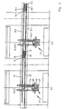
- the fixed drives 16, 17 generate the movement of Transfer system 2.1.
- Drive 16 is connected to gear 18, which acts on the horizontally movable rack 19.
- Drive 17 causes via gear 20, the horizontal movement the rack 21.
- the racks 19, 21 are in Operative connection with gear 22, 23 which the rack 24th drives.
- Structure and function of the rack 24 is comparable with a lifting column.
- the transfer system is in the movement level comparable to a cross slide constructed, i. movably mounted in 2 levels. Through this Structure are those described in more detail in Figure 2 Movements can be realized.
- For holding the workpieces serves the transversely mounted to the transport device, with Part holding means provided, Traverse 25.
- the transfer system 2.1 mirror image additionally on the opposite Press side to be grown.
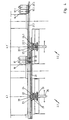
- FIG. 3 A plan view of Figure 3 shows Figure 4, in the rack 19 is not shown.
- an essential constructive Feature is the spatial offset of the respective Drive elements of the transfer systems 2.1 and 2.2 recognizable. This arrangement ensures a collision-free Movement.
- the gear 20 connected to the drive 17 therefore has a longer hub than the analog gear 20.1.
- the gear 20 drives the rack 21, thereby Gear 22 drives.
- the rotational movement of gear 22 is on the common shaft 38 of the gear 23 on the Rack 24 transmitted.
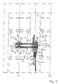
- Figure 5 shows the adjusting and lifting device 4 and a Detail of the transport system 2 in sectional view.
- the Adjustment and lifting device 4 on the one hand has the function Transport system 2 to one, based on the tool, regulate optimal transport height and on the other the Transport system 2 to avoid interference edges in the Tool change to move vertically upwards. This function can be done optionally for the entire transport system 2 or only for individual transport systems 2.1 - 2.n.
- Drive 31 drives by way of example Spindle nut system 32 and this leads to a Positional change of the mounting angle 33 in the vertical direction. In a horizontal arrangement is on the angle 33 the Transport system 2 stored, which is vertical for the entire Height adjustment required linear guide 34 attached. In a version with central adjustment would take place Drive 31 a propeller shaft provided with the Central drive is connected.
- the transport system 2.2 shows: Drive 16.1, with gear 18.1 which drives rack 19.1, which is guided in horizontal linear guides 35.
- the movement of the rack 19.1 drives gear 22.1, which is connected by a common shaft 38 with gear 23.1.
- the driven by the gear 23.1 rack is marked 24.1.
- the carriage 36 which carries out the movements is movably mounted in the horizontal linear guides 37 and the vertical linear guides 29.
- At the lower end of carriage 36 drive 26 is fixed, which can pivot about pivot axis 27 cross-beam 25, as described in Figure 3.
- the stationary drives 39, 40 are on the press stand 3rd arranged. Via gear 41, drive 39 drives rack 42 and drive 40 via gear 43 rack 44 at. racks 42, 44 are in operative connection with gear 45, which with Gear 46 is connected by a common shaft 47. Gear 46 drives rack 48, which in already detailed form described the transport system. 2 is driven. New is as a further drive means Timing belt 49 with pulleys 50. This timing belt 49 is on the one hand with vertical slide 51 in the attachment point 52nd firmly connected and on the other hand with the horizontal slide 53 in attachment point 54.
- linear guides 56 am Horizontal slide 53 and guide rails 57 on the base support 55 attached.
- pivoting about the pivot angle 28 and the axis of rotation 27 can, as described in Figure 3, also be provided.
- the invention is not limited to that described and illustrated Embodiment limited. It also includes all professional designs within the framework of the applicable Claim 1. So, as an alternative to the gear rack drives also spindle drives possibly with Reduction gears or toothed belts with toothed belt pulleys be used.
Landscapes
- Engineering & Computer Science (AREA)
- Mechanical Engineering (AREA)
- Press Drives And Press Lines (AREA)
- Testing Of Balance (AREA)
- Intermediate Stations On Conveyors (AREA)
- Reciprocating Conveyors (AREA)
- Magnetic Bearings And Hydrostatic Bearings (AREA)
- Jigging Conveyors (AREA)
Claims (13)
- Dispositif servant à transporter des pièces d'oeuvre dans une presse, un train de presses, une presse à étages pour pièces de grandes dimensions ou analogue, chaque station de traitement (6.1 à 6.n) comportant un dispositif de transport de pièce d'oeuvre indépendant (2.1 à 2.n) servant à effectuer un mouvement de transport biaxial, le dispositif de transport (2.1 à 2.n) comprenant un système d'entraínement pour une traverse (25) munie de moyens de maintien de pièce d'oeuvre, lequel système d'entraínement possède des entraínements statiques, notamment des moteurs d'entraínement (A1, A2, 16, 17, 39, 40), qui agissent chaque fois sur des moyens de transmission de mouvement (8 à 13, 18 à 24, 41 à 49), un réglage du sens de rotation et de la vitesse de rotation, voire de l'arrêt, des entraínements, notamment des moteurs d'entraínement, produisant un mouvement coordonné des moyens de transmission de mouvement de manière que n'importe quelle trajectoire programmable de la traverse (25) soit possible,
caractérisé en ce qu'il est prévu deux moteurs d'entraínement (A1, A2 ; 16, 17 ; 39, 40) qui agissent chacun sur une crémaillère (10, 11, 19, 21) ou analogue au moyen d'une roue dentée, les crémaillères ou analogue agissant ensemble sur une troisième roue dentée (12 ; 22, 23) et la troisième roue dentée (12 ; 22, 23) agissant pour sa part sur un moyen de transmission de mouvement linéairement mobile (13, 24), notamment sur une crémaillère ou une courroie crantée, pour déplacer la traverse (25). - Dispositif selon la revendication 1,
caractérisé en ce que la traverse (25) est montée sur un chariot (36, 53) avec guide linéaire (29, 37, 56, 57). - Dispositif selon la revendication 2,
caractérisé en ce que les moyens de transmission de mouvement (8 à 13, 16 à 24, 41 à 48) servant à effectuer un mouvement longitudinal et/ou un mouvement de montée ou de descente d'un chariot (36, 53) pour la traverse (25) sont réalisés sous forme d'entraínement à crémaillère. - Dispositif selon la revendication 2 ou 3,
caractérisé en ce qu'un mouvement longitudinal et/ou un mouvement de montée ou de descente du chariot (36, 53) pour la traverse (25) a lieu au moyen de deux crémaillères disposées parallèlement (19, 21, 42, 44) qui peuvent être entraínées, par l'intermédiaire de roues dentées (18, 20, 41, 43), par des moteurs d'entraínement statiques (16, 17, 39, 40). - Dispositif selon la revendication 4,
caractérisé en ce que les deux crémaillères disposées parallèlement (19, 21) sont disposées horizontalement. - Dispositif selon la revendication 4,
caractérisé en ce que les deux crémaillères disposées parallèlement (42, 44) sont disposées verticalement. - Dispositif selon l'une des revendications précédentes,
caractérisé en ce que deux crémaillères, ou analogue, disposées parallèlement (19, 21, 42, 44) agissent en commun sur des roues dentées motrices (22, 23, 45) de manière qu'il soit possible de régler un mouvement de montée ou de descente d'un chariot (36, 51, 53). - Dispositif selon la revendication 7,
caractérisé en ce que les roues dentées reliées ensemble (22, 23, 45, 46) par un arbre commun (38, 47) sont montées dans le chariot (36, 51) et en ce que la roue dentée (22, 45) est fixée à une extrémité de l'arbre (38, 47) et la roue dentée (23, 46) à l'autre extrémité de l'arbre (38, 47). - Dispositif selon l'une des revendications précédentes 2 à 8,
caractérisé en ce que la traverse (25) est disposée de manière à pouvoir pivoter et en ce que l'entraínement (26) pour le mouvement pivotant est fixé sur le chariot (36, 53). - Dispositif selon la revendication 1,
caractérisé en ce qu'il est prévu un dispositif de déplacement et de levage (4) pour un mouvement de montée ou de descente du système de transport (2) ou de sous-systèmes (2.1 à 2.n). - Dispositif selon la revendication 1,
caractérisé en ce que l'entraínement à roue dentée et crémaillère est remplacé par un entraínement à vis avec tige filetée et engrenage démultiplicateur ou par un entraínement à courroie crantée avec roue de courroie crantée. - Dispositif selon la revendication 11,
caractérisé en ce que le moyen de transmission de mouvement (49) est une courroie crantée (49) avec des poulies de renvoi (50) et en ce que la courroie crantée (49) est reliée solidairement à un chariot vertical (51) par l'intermédiaire d'un point d'appui (52) et à un chariot horizontal (53) par l'intermédiaire d'un point d'appui (54). - Dispositif selon la revendication 1,
caractérisé en ce que les moyens de transmission de mouvement (8 à 11, 18 à 22) s'étendent horizontalement dans la direction de transport et sont disposés en étant chaque fois décalés par rapport au moyen de transmission de mouvement suivant (18.1 à 22.1) transversalement au dispositif de transport.
Applications Claiming Priority (2)
| Application Number | Priority Date | Filing Date | Title |
|---|---|---|---|
| DE10005827 | 2000-02-10 | ||
| DE10005827 | 2000-02-10 |
Publications (3)
| Publication Number | Publication Date |
|---|---|
| EP1123761A2 EP1123761A2 (fr) | 2001-08-16 |
| EP1123761A3 EP1123761A3 (fr) | 2003-09-17 |
| EP1123761B1 true EP1123761B1 (fr) | 2005-02-02 |
Family
ID=7630415
Family Applications (1)
| Application Number | Title | Priority Date | Filing Date |
|---|---|---|---|
| EP00128237A Expired - Lifetime EP1123761B1 (fr) | 2000-02-10 | 2000-12-27 | Système de transport horizontal |
Country Status (6)
| Country | Link |
|---|---|
| US (1) | US7040853B2 (fr) |
| EP (1) | EP1123761B1 (fr) |
| BR (1) | BR0100460B1 (fr) |
| CA (1) | CA2331281C (fr) |
| DE (2) | DE10064930A1 (fr) |
| ES (1) | ES2235757T3 (fr) |
Cited By (1)
| Publication number | Priority date | Publication date | Assignee | Title |
|---|---|---|---|---|
| CN108674939A (zh) * | 2018-07-27 | 2018-10-19 | 重庆宏钢数控机床有限公司 | 工件接料自动翻转调节机构 |
Families Citing this family (7)
| Publication number | Priority date | Publication date | Assignee | Title |
|---|---|---|---|---|
| DE10352982B4 (de) * | 2003-11-13 | 2007-06-21 | Müller Weingarten AG | Gelenkarmtransportvorrichtung |
| DE102007051037B3 (de) * | 2007-10-25 | 2009-01-29 | Schuler Pressen Gmbh & Co. Kg | Schließkasten für eine Transfereinrichtung einer Presse |
| JP5869660B2 (ja) * | 2012-03-02 | 2016-02-24 | 株式会社エイチアンドエフ | 搬送装置 |
| TWI481804B (zh) * | 2012-10-03 | 2015-04-21 | Wei Hua Chaing | 瓶裝藥劑製程之自動化取送料軌道搬運車 |
| CN109132472A (zh) * | 2017-06-28 | 2019-01-04 | 江苏凯尔生物识别科技有限公司 | 可垂直运输的一体式自动接运料装置 |
| CN112273053B (zh) * | 2020-11-27 | 2022-06-17 | 南宁学院 | 一种柔性百香果采摘机械手末端执行器 |
| DE102022206118A1 (de) | 2022-06-20 | 2024-01-11 | Wafios Aktiengesellschaft | Umformmaschine mit mehreren Arbeitsstationen |
Family Cites Families (12)
| Publication number | Priority date | Publication date | Assignee | Title |
|---|---|---|---|---|
| DE3040400C1 (de) * | 1980-10-25 | 1982-02-18 | Maschinenfabrik Weingarten Ag, 7987 Weingarten | Be- und/oder Entladegeraet fuer Pressen,Stanzen o.dgl. Werkzeugmaschinen |
| US4614265A (en) | 1985-07-22 | 1986-09-30 | Danly Machine Corporation | Apparatus for automatically splitting transfer feed rails in a transfer feed press |
| US4714400A (en) * | 1986-04-14 | 1987-12-22 | Ibm Corporation | Plural robotic drive |
| JPH0757397B2 (ja) * | 1987-10-31 | 1995-06-21 | 石川島播磨重工業株式会社 | トランスファープレスの送り装置並に送り駆動装置 |
| DE4309661A1 (de) * | 1993-03-25 | 1994-12-01 | Mueller Weingarten Maschf | Transporteinrichtung zum Transportieren von Werkstücken in einer Pressenstraße, einer Großteil-Stufenpresse oder dergleichen |
| IT1272084B (it) * | 1993-12-17 | 1997-06-11 | Comau Spa | Robot industriale, particolarmente per la movimentazione di pezzi da una pressa all'altra in una linea di presse |
| DE4408449A1 (de) | 1994-03-12 | 1995-09-14 | Mueller Weingarten Maschf | Transportsystem |
| DE19521976A1 (de) | 1994-06-16 | 1995-12-21 | Mueller Weingarten Maschf | Transportsystem |
| US5611248A (en) * | 1995-06-02 | 1997-03-18 | Ats Automation Tooling Systems Inc. | Two-axis robot |
| DE19911795A1 (de) | 1999-03-17 | 2000-09-21 | Mueller Weingarten Maschf | Antriebssystem zur Automatisierung von Umformmaschinen |
| US6715981B1 (en) | 1999-03-17 | 2004-04-06 | Müller Weingarten AG | Transport system |
| US6196097B1 (en) * | 1999-05-07 | 2001-03-06 | Hormel Foods, Llc | Bacon slicer system |
-
2000
- 2000-12-23 DE DE10064930A patent/DE10064930A1/de not_active Withdrawn
- 2000-12-27 DE DE50009416T patent/DE50009416D1/de not_active Expired - Lifetime
- 2000-12-27 ES ES00128237T patent/ES2235757T3/es not_active Expired - Lifetime
- 2000-12-27 EP EP00128237A patent/EP1123761B1/fr not_active Expired - Lifetime
-
2001
- 2001-01-17 CA CA002331281A patent/CA2331281C/fr not_active Expired - Fee Related
- 2001-01-30 US US09/771,637 patent/US7040853B2/en not_active Expired - Fee Related
- 2001-02-08 BR BRPI0100460-3A patent/BR0100460B1/pt not_active IP Right Cessation
Cited By (1)
| Publication number | Priority date | Publication date | Assignee | Title |
|---|---|---|---|---|
| CN108674939A (zh) * | 2018-07-27 | 2018-10-19 | 重庆宏钢数控机床有限公司 | 工件接料自动翻转调节机构 |
Also Published As
| Publication number | Publication date |
|---|---|
| BR0100460A (pt) | 2001-09-11 |
| US20010014279A1 (en) | 2001-08-16 |
| EP1123761A3 (fr) | 2003-09-17 |
| CA2331281A1 (fr) | 2001-08-10 |
| CA2331281C (fr) | 2008-08-19 |
| ES2235757T3 (es) | 2005-07-16 |
| EP1123761A2 (fr) | 2001-08-16 |
| BR0100460B1 (pt) | 2009-01-13 |
| DE10064930A1 (de) | 2001-08-16 |
| DE50009416D1 (de) | 2005-03-10 |
| US7040853B2 (en) | 2006-05-09 |
Similar Documents
| Publication | Publication Date | Title |
|---|---|---|
| EP1313575B1 (fr) | Systeme de transport a bras articule | |
| EP0850709B1 (fr) | Dispositif de transfert et presse à étages multiples | |
| EP1161317B1 (fr) | Systeme de transport | |
| EP0672480B1 (fr) | Système de transport | |
| EP0671228B1 (fr) | Installation de transport pour pièces à usiner dans une presse | |
| WO2005075123A1 (fr) | Dispositif de transport de pieces dans des presses | |
| EP0693334B1 (fr) | Système de transport | |
| DE19628333A1 (de) | Umsetzeinrichtung für Blechteile in einer Pressenanlage | |
| EP0850710B1 (fr) | Transfert multiaxial flexible | |
| WO2006045283A1 (fr) | Dispositif pour transporter et changer de position des pieces d'usinage | |
| EP0901848B1 (fr) | Presse de transfert avec changement d' outil automatique | |
| EP1123761B1 (fr) | Système de transport horizontal | |
| EP0621093B1 (fr) | Train de presses avec dispositif de transfert pour transférer des pièces | |
| EP1000681B1 (fr) | Dispositif de transfer avec un entraínement combiné | |
| DE19925343A1 (de) | Transfereinrichtung | |
| EP0507098A1 (fr) | Dispositif de transport d'une presse transfert pour transporter des pièces de grande taille | |
| DE10158194A1 (de) | Vorrichtung zum Transport von Formteilen | |
| DE3826827C2 (de) | Vorrichtung zum Positionieren einer Blechtafel | |
| EP1000680A2 (fr) | Dispositif de transfer modulaire avec des entraínements pivotant et linéaire | |
| EP0847818B1 (fr) | Presse de transfert | |
| DE19506520A1 (de) | Transfervorrichtung | |
| DE10348643B3 (de) | Einrichtung zum Transport von Werkstücken |
Legal Events
| Date | Code | Title | Description |
|---|---|---|---|
| PUAI | Public reference made under article 153(3) epc to a published international application that has entered the european phase |
Free format text: ORIGINAL CODE: 0009012 |
|
| AK | Designated contracting states |
Kind code of ref document: A2 Designated state(s): AT BE CH CY DE DK ES FI FR GB GR IE IT LI LU MC NL PT SE TR |
|
| AX | Request for extension of the european patent |
Free format text: AL;LT;LV;MK;RO;SI |
|
| PUAL | Search report despatched |
Free format text: ORIGINAL CODE: 0009013 |
|
| AK | Designated contracting states |
Kind code of ref document: A3 Designated state(s): AT BE CH CY DE DK ES FI FR GB GR IE IT LI LU MC NL PT SE TR |
|
| AX | Request for extension of the european patent |
Extension state: AL LT LV MK RO SI |
|
| RIC1 | Information provided on ipc code assigned before grant |
Ipc: 7B 21D 43/05 A |
|
| 17P | Request for examination filed |
Effective date: 20031114 |
|
| 17Q | First examination report despatched |
Effective date: 20040401 |
|
| AKX | Designation fees paid |
Designated state(s): DE ES FR GB IT SE |
|
| GRAP | Despatch of communication of intention to grant a patent |
Free format text: ORIGINAL CODE: EPIDOSNIGR1 |
|
| GRAS | Grant fee paid |
Free format text: ORIGINAL CODE: EPIDOSNIGR3 |
|
| GRAA | (expected) grant |
Free format text: ORIGINAL CODE: 0009210 |
|
| AK | Designated contracting states |
Kind code of ref document: B1 Designated state(s): DE ES FR GB IT SE |
|
| REG | Reference to a national code |
Ref country code: GB Ref legal event code: FG4D Free format text: NOT ENGLISH |
|
| GBT | Gb: translation of ep patent filed (gb section 77(6)(a)/1977) |
Effective date: 20050202 |
|
| REG | Reference to a national code |
Ref country code: IE Ref legal event code: FG4D Free format text: GERMAN |
|
| REF | Corresponds to: |
Ref document number: 50009416 Country of ref document: DE Date of ref document: 20050310 Kind code of ref document: P |
|
| REG | Reference to a national code |
Ref country code: SE Ref legal event code: TRGR |
|
| REG | Reference to a national code |
Ref country code: ES Ref legal event code: FG2A Ref document number: 2235757 Country of ref document: ES Kind code of ref document: T3 |
|
| PLBE | No opposition filed within time limit |
Free format text: ORIGINAL CODE: 0009261 |
|
| STAA | Information on the status of an ep patent application or granted ep patent |
Free format text: STATUS: NO OPPOSITION FILED WITHIN TIME LIMIT |
|
| ET | Fr: translation filed | ||
| 26N | No opposition filed |
Effective date: 20051103 |
|
| PGFP | Annual fee paid to national office [announced via postgrant information from national office to epo] |
Ref country code: GB Payment date: 20081219 Year of fee payment: 9 |
|
| PGFP | Annual fee paid to national office [announced via postgrant information from national office to epo] |
Ref country code: SE Payment date: 20091218 Year of fee payment: 10 |
|
| PGFP | Annual fee paid to national office [announced via postgrant information from national office to epo] |
Ref country code: FR Payment date: 20100105 Year of fee payment: 10 |
|
| GBPC | Gb: european patent ceased through non-payment of renewal fee |
Effective date: 20091227 |
|
| PG25 | Lapsed in a contracting state [announced via postgrant information from national office to epo] |
Ref country code: GB Free format text: LAPSE BECAUSE OF NON-PAYMENT OF DUE FEES Effective date: 20091227 |
|
| PGFP | Annual fee paid to national office [announced via postgrant information from national office to epo] |
Ref country code: IT Payment date: 20101229 Year of fee payment: 11 |
|
| REG | Reference to a national code |
Ref country code: FR Ref legal event code: ST Effective date: 20110831 |
|
| REG | Reference to a national code |
Ref country code: SE Ref legal event code: EUG |
|
| PG25 | Lapsed in a contracting state [announced via postgrant information from national office to epo] |
Ref country code: SE Free format text: LAPSE BECAUSE OF NON-PAYMENT OF DUE FEES Effective date: 20101228 |
|
| PG25 | Lapsed in a contracting state [announced via postgrant information from national office to epo] |
Ref country code: FR Free format text: LAPSE BECAUSE OF NON-PAYMENT OF DUE FEES Effective date: 20110103 |
|
| PGFP | Annual fee paid to national office [announced via postgrant information from national office to epo] |
Ref country code: ES Payment date: 20111219 Year of fee payment: 12 |
|
| PG25 | Lapsed in a contracting state [announced via postgrant information from national office to epo] |
Ref country code: IT Free format text: LAPSE BECAUSE OF NON-PAYMENT OF DUE FEES Effective date: 20121227 |
|
| REG | Reference to a national code |
Ref country code: ES Ref legal event code: FD2A Effective date: 20140509 |
|
| PG25 | Lapsed in a contracting state [announced via postgrant information from national office to epo] |
Ref country code: ES Free format text: LAPSE BECAUSE OF NON-PAYMENT OF DUE FEES Effective date: 20121228 |
|
| PGFP | Annual fee paid to national office [announced via postgrant information from national office to epo] |
Ref country code: DE Payment date: 20151110 Year of fee payment: 16 |
|
| REG | Reference to a national code |
Ref country code: DE Ref legal event code: R119 Ref document number: 50009416 Country of ref document: DE |
|
| PG25 | Lapsed in a contracting state [announced via postgrant information from national office to epo] |
Ref country code: DE Free format text: LAPSE BECAUSE OF NON-PAYMENT OF DUE FEES Effective date: 20170701 |