EP1121234B1 - A matrix and method of producing said matrix - Google Patents
A matrix and method of producing said matrix Download PDFInfo
- Publication number
- EP1121234B1 EP1121234B1 EP99970352A EP99970352A EP1121234B1 EP 1121234 B1 EP1121234 B1 EP 1121234B1 EP 99970352 A EP99970352 A EP 99970352A EP 99970352 A EP99970352 A EP 99970352A EP 1121234 B1 EP1121234 B1 EP 1121234B1
- Authority
- EP
- European Patent Office
- Prior art keywords
- matrix
- layer
- microstructure
- plastic
- wear
- Prior art date
- Legal status (The legal status is an assumption and is not a legal conclusion. Google has not performed a legal analysis and makes no representation as to the accuracy of the status listed.)
- Expired - Lifetime
Links
- 239000011159 matrix material Substances 0.000 title claims abstract description 184
- 238000000034 method Methods 0.000 title claims description 92
- 239000004033 plastic Substances 0.000 claims abstract description 164
- 229920003023 plastic Polymers 0.000 claims abstract description 164
- 229910052751 metal Inorganic materials 0.000 claims abstract description 70
- 239000002184 metal Substances 0.000 claims abstract description 70
- 238000010438 heat treatment Methods 0.000 claims abstract description 23
- 239000004065 semiconductor Substances 0.000 claims abstract description 7
- 239000002131 composite material Substances 0.000 claims description 72
- 239000000463 material Substances 0.000 claims description 63
- 230000008569 process Effects 0.000 claims description 47
- 238000004519 manufacturing process Methods 0.000 claims description 39
- 238000011049 filling Methods 0.000 claims description 19
- 238000007747 plating Methods 0.000 claims description 15
- 238000000576 coating method Methods 0.000 claims description 12
- 230000010076 replication Effects 0.000 claims description 12
- 239000011248 coating agent Substances 0.000 claims description 11
- 230000002093 peripheral effect Effects 0.000 claims description 10
- 238000004544 sputter deposition Methods 0.000 claims description 8
- 239000000203 mixture Substances 0.000 claims description 7
- 239000010453 quartz Substances 0.000 claims description 7
- VYPSYNLAJGMNEJ-UHFFFAOYSA-N silicon dioxide Inorganic materials O=[Si]=O VYPSYNLAJGMNEJ-UHFFFAOYSA-N 0.000 claims description 7
- 239000004593 Epoxy Substances 0.000 claims description 6
- 229910052799 carbon Inorganic materials 0.000 claims description 6
- 238000005253 cladding Methods 0.000 claims description 6
- 239000000945 filler Substances 0.000 claims description 6
- 229920005573 silicon-containing polymer Polymers 0.000 claims description 6
- NRTOMJZYCJJWKI-UHFFFAOYSA-N Titanium nitride Chemical compound [Ti]#N NRTOMJZYCJJWKI-UHFFFAOYSA-N 0.000 claims description 5
- 238000005137 deposition process Methods 0.000 claims description 3
- 230000001678 irradiating effect Effects 0.000 claims description 3
- 239000010410 layer Substances 0.000 claims 30
- 150000004767 nitrides Chemical class 0.000 claims 1
- 239000002344 surface layer Substances 0.000 claims 1
- 238000001746 injection moulding Methods 0.000 description 20
- 238000001816 cooling Methods 0.000 description 13
- 238000000465 moulding Methods 0.000 description 13
- PXHVJJICTQNCMI-UHFFFAOYSA-N Nickel Chemical compound [Ni] PXHVJJICTQNCMI-UHFFFAOYSA-N 0.000 description 10
- 238000005266 casting Methods 0.000 description 7
- JHJNPOSPVGRIAN-SFHVURJKSA-N n-[3-[(1s)-1-[[6-(3,4-dimethoxyphenyl)pyrazin-2-yl]amino]ethyl]phenyl]-5-methylpyridine-3-carboxamide Chemical compound C1=C(OC)C(OC)=CC=C1C1=CN=CC(N[C@@H](C)C=2C=C(NC(=O)C=3C=C(C)C=NC=3)C=CC=2)=N1 JHJNPOSPVGRIAN-SFHVURJKSA-N 0.000 description 7
- 238000000748 compression moulding Methods 0.000 description 6
- 238000000151 deposition Methods 0.000 description 6
- 238000013461 design Methods 0.000 description 6
- 230000008021 deposition Effects 0.000 description 5
- 238000004049 embossing Methods 0.000 description 5
- 238000002347 injection Methods 0.000 description 5
- 239000007924 injection Substances 0.000 description 5
- 229910052759 nickel Inorganic materials 0.000 description 5
- 238000009826 distribution Methods 0.000 description 4
- 238000000227 grinding Methods 0.000 description 4
- 238000003754 machining Methods 0.000 description 4
- 238000007711 solidification Methods 0.000 description 4
- 230000008023 solidification Effects 0.000 description 4
- 239000000243 solution Substances 0.000 description 4
- 230000003319 supportive effect Effects 0.000 description 4
- 238000005299 abrasion Methods 0.000 description 3
- 239000002322 conducting polymer Substances 0.000 description 3
- 229920001940 conductive polymer Polymers 0.000 description 3
- 230000001419 dependent effect Effects 0.000 description 3
- 239000000835 fiber Substances 0.000 description 3
- 239000012530 fluid Substances 0.000 description 3
- PCHJSUWPFVWCPO-UHFFFAOYSA-N gold Chemical compound [Au] PCHJSUWPFVWCPO-UHFFFAOYSA-N 0.000 description 3
- 229910052737 gold Inorganic materials 0.000 description 3
- 239000010931 gold Substances 0.000 description 3
- 238000009499 grossing Methods 0.000 description 3
- 239000007769 metal material Substances 0.000 description 3
- 239000002245 particle Substances 0.000 description 3
- 238000005498 polishing Methods 0.000 description 3
- 229910052709 silver Inorganic materials 0.000 description 3
- 239000004332 silver Substances 0.000 description 3
- 238000012546 transfer Methods 0.000 description 3
- XLYOFNOQVPJJNP-UHFFFAOYSA-N water Substances O XLYOFNOQVPJJNP-UHFFFAOYSA-N 0.000 description 3
- 241000234671 Ananas Species 0.000 description 2
- 235000007119 Ananas comosus Nutrition 0.000 description 2
- BQCADISMDOOEFD-UHFFFAOYSA-N Silver Chemical compound [Ag] BQCADISMDOOEFD-UHFFFAOYSA-N 0.000 description 2
- 230000008859 change Effects 0.000 description 2
- 230000000295 complement effect Effects 0.000 description 2
- 238000010276 construction Methods 0.000 description 2
- 238000011161 development Methods 0.000 description 2
- 230000000694 effects Effects 0.000 description 2
- 239000011521 glass Substances 0.000 description 2
- 239000012212 insulator Substances 0.000 description 2
- 230000001788 irregular Effects 0.000 description 2
- 238000000608 laser ablation Methods 0.000 description 2
- 229910021645 metal ion Inorganic materials 0.000 description 2
- 229920000642 polymer Polymers 0.000 description 2
- 230000003362 replicative effect Effects 0.000 description 2
- QDZRBIRIPNZRSG-UHFFFAOYSA-N titanium nitrate Chemical compound [O-][N+](=O)O[Ti](O[N+]([O-])=O)(O[N+]([O-])=O)O[N+]([O-])=O QDZRBIRIPNZRSG-UHFFFAOYSA-N 0.000 description 2
- OKTJSMMVPCPJKN-UHFFFAOYSA-N Carbon Chemical compound [C] OKTJSMMVPCPJKN-UHFFFAOYSA-N 0.000 description 1
- RYGMFSIKBFXOCR-UHFFFAOYSA-N Copper Chemical compound [Cu] RYGMFSIKBFXOCR-UHFFFAOYSA-N 0.000 description 1
- FHKPLLOSJHHKNU-INIZCTEOSA-N [(3S)-3-[8-(1-ethyl-5-methylpyrazol-4-yl)-9-methylpurin-6-yl]oxypyrrolidin-1-yl]-(oxan-4-yl)methanone Chemical compound C(C)N1N=CC(=C1C)C=1N(C2=NC=NC(=C2N=1)O[C@@H]1CN(CC1)C(=O)C1CCOCC1)C FHKPLLOSJHHKNU-INIZCTEOSA-N 0.000 description 1
- 230000006978 adaptation Effects 0.000 description 1
- 230000004888 barrier function Effects 0.000 description 1
- 230000015572 biosynthetic process Effects 0.000 description 1
- 238000004140 cleaning Methods 0.000 description 1
- 238000007796 conventional method Methods 0.000 description 1
- 229910052802 copper Inorganic materials 0.000 description 1
- 239000010949 copper Substances 0.000 description 1
- 230000007547 defect Effects 0.000 description 1
- 230000002950 deficient Effects 0.000 description 1
- 239000010432 diamond Substances 0.000 description 1
- 229910003460 diamond Inorganic materials 0.000 description 1
- 238000004512 die casting Methods 0.000 description 1
- 238000005530 etching Methods 0.000 description 1
- 239000007789 gas Substances 0.000 description 1
- 238000005338 heat storage Methods 0.000 description 1
- 238000005286 illumination Methods 0.000 description 1
- 150000002739 metals Chemical class 0.000 description 1
- 238000012986 modification Methods 0.000 description 1
- 230000004048 modification Effects 0.000 description 1
- 239000002991 molded plastic Substances 0.000 description 1
- 239000012811 non-conductive material Substances 0.000 description 1
- 239000003921 oil Substances 0.000 description 1
- 230000003287 optical effect Effects 0.000 description 1
- 238000013021 overheating Methods 0.000 description 1
- 239000002861 polymer material Substances 0.000 description 1
- 239000000843 powder Substances 0.000 description 1
- 238000009747 press moulding Methods 0.000 description 1
- 238000003825 pressing Methods 0.000 description 1
- 238000003672 processing method Methods 0.000 description 1
- 230000001105 regulatory effect Effects 0.000 description 1
- 230000002787 reinforcement Effects 0.000 description 1
- 230000003014 reinforcing effect Effects 0.000 description 1
- 230000031070 response to heat Effects 0.000 description 1
- 230000000630 rising effect Effects 0.000 description 1
- 239000010703 silicon Substances 0.000 description 1
- 229910052710 silicon Inorganic materials 0.000 description 1
- 239000007787 solid Substances 0.000 description 1
- 238000009987 spinning Methods 0.000 description 1
- 238000007592 spray painting technique Methods 0.000 description 1
- 239000000126 substance Substances 0.000 description 1
- 230000008646 thermal stress Effects 0.000 description 1
- 238000001771 vacuum deposition Methods 0.000 description 1
- 238000009834 vaporization Methods 0.000 description 1
- 238000005406 washing Methods 0.000 description 1
Images

Classifications
-
- B—PERFORMING OPERATIONS; TRANSPORTING
- B29—WORKING OF PLASTICS; WORKING OF SUBSTANCES IN A PLASTIC STATE IN GENERAL
- B29C—SHAPING OR JOINING OF PLASTICS; SHAPING OF MATERIAL IN A PLASTIC STATE, NOT OTHERWISE PROVIDED FOR; AFTER-TREATMENT OF THE SHAPED PRODUCTS, e.g. REPAIRING
- B29C33/00—Moulds or cores; Details thereof or accessories therefor
- B29C33/56—Coatings, e.g. enameled or galvanised; Releasing, lubricating or separating agents
- B29C33/565—Consisting of shell-like structures supported by backing material
-
- B—PERFORMING OPERATIONS; TRANSPORTING
- B29—WORKING OF PLASTICS; WORKING OF SUBSTANCES IN A PLASTIC STATE IN GENERAL
- B29C—SHAPING OR JOINING OF PLASTICS; SHAPING OF MATERIAL IN A PLASTIC STATE, NOT OTHERWISE PROVIDED FOR; AFTER-TREATMENT OF THE SHAPED PRODUCTS, e.g. REPAIRING
- B29C33/00—Moulds or cores; Details thereof or accessories therefor
- B29C33/02—Moulds or cores; Details thereof or accessories therefor with incorporated heating or cooling means
-
- B—PERFORMING OPERATIONS; TRANSPORTING
- B29—WORKING OF PLASTICS; WORKING OF SUBSTANCES IN A PLASTIC STATE IN GENERAL
- B29C—SHAPING OR JOINING OF PLASTICS; SHAPING OF MATERIAL IN A PLASTIC STATE, NOT OTHERWISE PROVIDED FOR; AFTER-TREATMENT OF THE SHAPED PRODUCTS, e.g. REPAIRING
- B29C33/00—Moulds or cores; Details thereof or accessories therefor
- B29C33/42—Moulds or cores; Details thereof or accessories therefor characterised by the shape of the moulding surface, e.g. ribs or grooves
- B29C33/424—Moulding surfaces provided with means for marking or patterning
-
- B—PERFORMING OPERATIONS; TRANSPORTING
- B29—WORKING OF PLASTICS; WORKING OF SUBSTANCES IN A PLASTIC STATE IN GENERAL
- B29C—SHAPING OR JOINING OF PLASTICS; SHAPING OF MATERIAL IN A PLASTIC STATE, NOT OTHERWISE PROVIDED FOR; AFTER-TREATMENT OF THE SHAPED PRODUCTS, e.g. REPAIRING
- B29C45/00—Injection moulding, i.e. forcing the required volume of moulding material through a nozzle into a closed mould; Apparatus therefor
- B29C45/17—Component parts, details or accessories; Auxiliary operations
- B29C45/26—Moulds
- B29C45/263—Moulds with mould wall parts provided with fine grooves or impressions, e.g. for record discs
- B29C45/2632—Stampers; Mountings thereof
-
- G—PHYSICS
- G11—INFORMATION STORAGE
- G11B—INFORMATION STORAGE BASED ON RELATIVE MOVEMENT BETWEEN RECORD CARRIER AND TRANSDUCER
- G11B7/00—Recording or reproducing by optical means, e.g. recording using a thermal beam of optical radiation by modifying optical properties or the physical structure, reproducing using an optical beam at lower power by sensing optical properties; Record carriers therefor
- G11B7/24—Record carriers characterised by shape, structure or physical properties, or by the selection of the material
- G11B7/26—Apparatus or processes specially adapted for the manufacture of record carriers
- G11B7/263—Preparing and using a stamper, e.g. pressing or injection molding substrates
-
- B—PERFORMING OPERATIONS; TRANSPORTING
- B29—WORKING OF PLASTICS; WORKING OF SUBSTANCES IN A PLASTIC STATE IN GENERAL
- B29C—SHAPING OR JOINING OF PLASTICS; SHAPING OF MATERIAL IN A PLASTIC STATE, NOT OTHERWISE PROVIDED FOR; AFTER-TREATMENT OF THE SHAPED PRODUCTS, e.g. REPAIRING
- B29C45/00—Injection moulding, i.e. forcing the required volume of moulding material through a nozzle into a closed mould; Apparatus therefor
- B29C45/17—Component parts, details or accessories; Auxiliary operations
- B29C45/26—Moulds
- B29C45/263—Moulds with mould wall parts provided with fine grooves or impressions, e.g. for record discs
- B29C45/2632—Stampers; Mountings thereof
- B29C2045/2634—Stampers; Mountings thereof mounting layers between stamper and mould or on the rear surface of the stamper
-
- B—PERFORMING OPERATIONS; TRANSPORTING
- B29—WORKING OF PLASTICS; WORKING OF SUBSTANCES IN A PLASTIC STATE IN GENERAL
- B29L—INDEXING SCHEME ASSOCIATED WITH SUBCLASS B29C, RELATING TO PARTICULAR ARTICLES
- B29L2017/00—Carriers for sound or information
- B29L2017/001—Carriers of records containing fine grooves or impressions, e.g. disc records for needle playback, cylinder records
- B29L2017/003—Records or discs
- B29L2017/005—CD''s, DVD''s
-
- Y—GENERAL TAGGING OF NEW TECHNOLOGICAL DEVELOPMENTS; GENERAL TAGGING OF CROSS-SECTIONAL TECHNOLOGIES SPANNING OVER SEVERAL SECTIONS OF THE IPC; TECHNICAL SUBJECTS COVERED BY FORMER USPC CROSS-REFERENCE ART COLLECTIONS [XRACs] AND DIGESTS
- Y10—TECHNICAL SUBJECTS COVERED BY FORMER USPC
- Y10S—TECHNICAL SUBJECTS COVERED BY FORMER USPC CROSS-REFERENCE ART COLLECTIONS [XRACs] AND DIGESTS
- Y10S425/00—Plastic article or earthenware shaping or treating: apparatus
- Y10S425/81—Sound record
Definitions
- the present invention relates to a method of producing a matrix that can be used in a compression moulding, embossing, injection moulding and/or other plastic element-producing machine.
- the present invention relates to a matrix having a surface, or a part of said surface, which is provided with a negative microstructure that can be replicated as a positive microstructure, on a surface of a plastic element, such as a compact disc (CD) formed in such a machine.
- a plastic element such as a compact disc (CD) formed in such a machine.
- the invention also relates to a matrix manufactured by said method, the use of said matrix to form a plastic element and the plastic element so formed.
- positive surface structure shall be understood to mean the surface structure (including topographic surface features such as microstructures or plane surfaces or parts of surfaces) that appears on a plastic element produced in a plastic element-producing machine, and that by “negative surface structure” is meant the inverse of the positive surface structure, i.e. the surface structure exhibited by a matrix used in such a machine.
- plastic composite is meant a curable mixture of polymeric material and a filling material, where the filler is normally present in surplus.
- a matrix first wear surface that is formed on a first wear layer
- a matrix second wear surface that is formed on a second wear layer
- the first wear surface is the surface of the matrix that carries a microstructure and that faces towards the manufactured plastic element
- the second wear surface is the surface of the matrix, also referred to as the rear side, which is preferably planar and lies in abutment with the corresponding planar support surface of a mould half, It will be understood that these latter two surfaces need not necessarily be planar but that they shall connect with one another so as to be able to take-up forces generated during the moulding or casting process e.g. they can have complementary shapes.
- Matrices of this kind can be produced by coating a master or an original that has a positive microstructure on one surface with a metal layer or a metallic coating and removing the negative-microstructured metal layer from the master to thereby obtain a metal plate that can serve as a matrix in the compression moulding, embossing and/or injection moulding press.
- each mould half can have its own matrix and a flowing, hot (approximately 400° C) plastic mass is pressed under high pressure into a delimited mould cavity formed by cavities in brought together mould halves.
- the flowing hot plastic mass is then allowed to solidify (at approximately 140° C) between the brought together mould halves before the mould halves are opened and the solidified element can be pressed out. See for instance EP 400762.
- Lithographic processes in particular lithographic processes that have been developed primarily for use in the micro-electrical field, are an example of known methods for producing a master.
- One of these methods is based on etching a semiconductor surface and/or depositing material thereon.
- Other methods are based on the removal of parts of material with the aid of a laser, so-called laser ablation, with the aid of traditional NC-machines, with the aid of precision-controlled, high-speed diamond millers, with the aid of electric discharge machining (EDM); wire EDM and/or some other suitable method.
- EDM electric discharge machining
- Such originals or masters are normally produced from a material that is chosen to be suitable with respect to a given machining process.
- the material is most often a sheet of silicon, glass or quartz, whereas in the case of laser ablation the material most often used is a sheet of plastic composite and/or a polymeric material.
- plastics and soft metals may both be suitable.
- One manufacturing method is based on first producing a master on a surface of a glass plate, a semiconductor plate or a metal plate, coating the surface with a light-sensitive layer and exposing selected surface sections of this light-sensitive layer through the medium of a laser or the like, and washing and cleaning the selected surface sections.
- a metal layer is applied to the exposed and cleaned surface of the master, through the medium of a sputtering process, a vapour deposition process, and/or through the medium of a plating or cladding process, for the length of time required to form a metal plate.
- the metal plate can then be removed from the master.
- the metal plate has a first surface which exhibits a negative microstructure which is intended to face towards the inside of a mould cavity.
- the metal plate can be used as a matrix after further machining, i.e. smoothing, of a second surface that faces towards the mould half in the machine.
- the master pattern will be embossed on the rear side of the matrix or metal plate
- a first measure is to apply an extremely thick layer of metal by means of a plating process or some equivalent process.
- the resulting plate which is intended to serve as the matrix will be strong and stable,
- the plate can then be placed in equipment in which the metallic rear side of the plate can be smoothed down or levelled mechanically, such as by a grinding, polishing and/or lapping process, while still retaining sufficient strength to serve as a matrix
- the adhesion between the master microstructure and the conductive metal layer in the matrix must be capable of withstanding the tensions that are generated in the interface therebetween
- One known method in this respect uses a pulsed field instead of a direct current with constant field.
- a metallic layer takes longer to grow with a pulsed field than with a direct current.
- this method enables the deep microstructure parts to be coated and built-up more quickly than the shallower microstructure parts, meaning that the deep structures will be overgrown and the metallic rear side will become relatively flat.
- the coating time in the first method will be longer than the coating time in the latter method, whereas the time taken to smooth down said surface will be shorter in the first method than in the second method.
- Heat is applied in order to thereby make the composite plastic or the plastic material used more easily flowing against the surface of the matrix in order to in this way be able to improve the replicating of the microstructure.
- a technical problem resides in providing a simple method of producing a matrix that can be adapted for use in a compression moulding, embossing and/or injection moulding press, where the matrix is provided on one surface with a negative microstructure that can be replicated in the machine as a positive microstructure on a surface part of a produced plastic element, through the medium of a plastic composite or plastic material, and therewith obtain an inexpensive matrix that has a sharply defined microstructure.
- Another technical problem is one of providing with the aid of simple means conditions that will enable the matrix to be given a microstructure-related first wear-resistant surface formed on a first wear-resistant layer which has an adaptable and relatively high abrasion resistance.
- Another technical problem is one of providing with the aid of simple means and measures conditions which will enable the matrix to be built-up of at least two layers, a thin first wear-resistant layer presenting said microstructure-related surface, and a layer which stiffens or reinforces said thin wear-resistant layer, this latter layer being a thicker layer and which is referred to hereinafter as the carrier element.
- Still another technical problem is one of providing with simple measures conditions that will enable the material used in the first thin layer and the material used in the thick layer or carrier element to be chosen with such properties and/or thicknesses as to fulfil predetermined requirements and conditions.
- Another technical problem is one of realising the significance of and the advantages that are gained with enabling the matrix to be produced by metal coating, with the aid of a metal coating process, a master that has on one surface a positive microstructure, and coating this thin metal layer with a plastic composite so as to form said carrier element.
- Another technical problem is one of producing with simple means and measures a matrix which is formed substantially or exclusively from a plastic composite and which can be used in a machine, where the time taken to produce the matrix from a master has been considerably shortened, among other things by being able to eliminate or at least substantially reduce the time taken to form on the plastic composite a flat rear side of the matrix for close abutment of said rear side with one of the two mould halves of said machine.
- Yet another technical problem resides in realising the significance of producing the matrix from a master and to apply to the surface-carried positive microstructure a thin metal layer and to permit said metal layer to show on the rear side of the microstructure irregularities that correspond essentially to said microstructure, and to realise the advantages of filling said irregularities with a supportive plastic composite which, when cured forms a supportive sheet-like carrier element, instead of building up the entire matrix with a thick metal layer
- Another technical problem is one of realising the significance of filling-out said irregularities with a chosen plastic composite and forming the carrier element in a special mould cavity
- Still another technical problem is one of realising the significance of and the advantages gained by, forming said plastic composite, and therewith said carrier element, from a mixture of plastic material or polymeric material and a filler material such as quartz-filled or metal-filled epoxy or silicone polymer.
- Another technical problem is one of realising the significance of, and the advantages that are gained by, using a plastic composite and therewith a carrier element that has a coefficient of linear expansion and/or a thermal conductivity and/or a heat capacity that is adapted for a given process carried out in the machine, and also to the design of said machine.
- a technical problem resides in utilising a specially selected curing process so as to impart to the chosen plastic composite a hardness and/or hardening time which is dependent on the application concerned, by applying heat to chosen parts of the plastic composite or plastic mass and/or irradiating the plastic composite or said mass with UV-light, or by using a bicomponent plastic composite.
- Still another technical problem is one of realising the significance of providing a first wear-resistant layer and/or a metal layer thin, and to select a plastic composite, and therewith a carrier element, that has a low heat transfer capacity so that the plastic mass pressed through the machine and between the mould part will be kept warm.
- Another technical problem is one of realising the significance of and the advantages that are gained and the dimensioning rules required with respect to the application of a second wear-resistant layer on the carrier element surface distal from the microstructured surface of said metal layer.
- Another technical problem is one of realising the significance of forming said second wear-resistant layer from a material that has low friction qualities against the flat surface of said mould half and high abrasive resistance, such as titanium nitride or diamond-like-carbon (DLC).
- a material that has low friction qualities against the flat surface of said mould half and high abrasive resistance such as titanium nitride or diamond-like-carbon (DLC).
- Still another technical problem is one of realising the significance of applying said thin metal layer to said master or original when said original consists of an electrically non-conductive material, by means of a sputtering process and/or by means of vapour deposition, and applying said thin metal layer by means of a metal plating process when said material is electrically conductive.
- Another technical problem is one of choosing the thickness of the metal layer within predetermined limits on the basis of the application performed in the injection moulding press
- Still another technical problem is one of realising the significance of and the advantages that are to be gained by creating conditions such as to greatly simplify smoothing-down of the rear side of the matrix and of the carrier element and/or totally eliminating the need of such smoothing
- At least one, of a plurality of available layers is selected to have different thicknesses, thicker at a section which requires lower heat energy and thinner at a section which requires higher heat energy.
- the present invention specially relates to an application where the layer having the negative surface structure relating to the matrix is in the form of a microstructure and therewith being able to realise the significance of allowing the heat production be adapted at selected cross-sections to be higher than at other surface sections, in order to in this way similarly increase the replication accuracy and mould filling
- the present invention takes as its starting point a method of producing a matrix that includes on one surface a negative microstructure which can be replicated in an injection moulding press as a positive microstructure on a prepared plastic element, from a plastic composite or a plastic material
- the invention is based on the concept of enabling said matrix to be produced by covering a master or an original that has a positive microstructure on one side thereof with a layer of covering material
- said plastic composite is applied to level out said irregularities in a mould cavity.
- the plastic composite, and therewith the carrier element is comprised of a polymeric material and a filler material, such as quartz-filled or metal-filled or carbon fibre-filled or other fibre- or particle-filled epoxy polymer or silicone polymer.
- a filler material such as quartz-filled or metal-filled or carbon fibre-filled or other fibre- or particle-filled epoxy polymer or silicone polymer.
- the plastic composite, and therewith the carrier element have a coefficient of linear expansion and/or a thermal conductivity and/or a heat capacity adapted for a given process carried out in a machine and also to the design of said machine
- the plastic composite is cured in a manner suitably adapted for injection moulding, such as by applying heat and/or irradiation with UV-light.
- the plastic composite may also be a bicomponent composite.
- a plastic composite, therewith the carrier element, located beneath a hard wear-resistant layer serving as a first wear-resistant surface has an adapted thermal conductivity and/or an adapted heat capacity so that the plastic mass pressed forwards in the machine can be kept warm while achieving short cycle times at the same time.
- the plastic composite, and therewith the carrier element can be coated with a second wear-resistant layer on the surface that lies distal from the first wear-resistant surface, so as to reinforce the matrix construction against abrasive wear
- This second wear-resistant layer may be comprised of titanium nitrate or DLC
- said thin first wear-resistant layer is comprised of a metal layer and that said metal layer shall be applied by a sputtering process and/or a vapour deposition process, or a metal plating process
- the thickness of the first wear-resistant layer is carefully chosen with respect to application and with respect to the design of the injection moulding press.
- the invention also provides a matrix, which is adapted for use in compression moulding machine, an embossing machine and/or an injection moulding press.
- the microstructured surface of the matrix shall be comprised of a thin, first wear-resistant layer, such as a metal layer, and that said first wear-resistant layer is preferably supported by a carrier element.
- the carrier element is conveniently comprised of a thick plastic composite layer
- the carrier element be comprised of a plastic composite comprised of a polymeric material mixed with a filler material, such as a quartz-filled or metal-filled or other fibre- or particle-filled epoxy polymer or silicone polymer.
- the carrier element will be comprised of a plastic composite that has a coefficient of linear expansion and/or a thermal conductivity and/or a heat capacity adapted to a chosen process and to a chosen design of the injection moulding press.
- the carrier element is comprised of a plastic composite that can be cured by applying heat and/or irradiating said composite with UV-light.
- the plastic composite may be a bicomponent composite.
- the carrier element and the thick plastic composite layer may also be comprised of a plastic composite that has a pronounced low thermal conductivity e.g. less than 2 W/m/°K.
- the carrier element can be strengthened, primarily from an abrasion aspect, for instance with the aid of a second wear-resistant layer on the surface distal from the metal layer surface.
- This reinforcing second wear-resistant layer may be comprised of titanium nitride or DLC in this case.
- heating means be provided for supplying heat energy to said matrix.
- said heating means should be formed by the supplying of electrical heat energy to the whole, or parts, of just the matrix, that said electrical heat energy is supplied via or immediately beside the outer layer belonging to the matrix and that said layer and/or the supporting layer consist(s) of an electrically conducting and/or electrically semi-conducting material.
- the layer belonging to the matrix is selected from a material with a resistivity of between 0.025 and 0.12 Ohms x mm 2 /m.
- said layer belonging to the matrix is supported by a further layer with a resistivity of 0.3 Ohms x mm 2 /m or less.
- Such a supporting layer should be formed from a heat-producing layer.
- the supporting layer can also consist of a material with a higher resistivity and positioned intermediate two layers having low resistivity.
- the invention further shows that such an intermediate positioned layer can be selected to have different thicknesses, thicker at surface sections that require low heat energy and thinner at surface sections that require high heat energy.
- the invention specially teaches the application of that the layer having the negative surface structure belonging to the matrix can have the form of a microstructure and therewith requires that the heat production should be adapted so that it is greater at selected surface sections than at other surface sections in order to thereby increase the replication accuracy and mould filling.
- the electrical heat energy can be supplied through applying a voltage to peripheral surface parts for a selected layer.
- the electrical heat energy can be supplied through applying a voltage to peripheral surface parts of different layers having low resistivity in order to produce heat within an intermediate positioned layer having a high resistivity.
- a method of producing a matrix adapted for use in a compression moulding machine and/or an injection moulding press in accordance with the present invention reside in the creation of conditions which enable the matrix to be produced more simply.
- this can be achieved by applying a thin first wear-resistant layer to the positive microstructure on one side of a master and thereafter applying a plastic composite in order to fill-out irregularities in said wear-resistant layer and to form a carrier element.
- the heat transfer capacity and/or the heat capacity of the matrix can also be adapted so as to enhance the replication capacity in the production process, such as the embossment process and/or the injection moulding process, by virtue of the fact that the Forming plastic material will not freeze as soon as it comes into contact with the microstructured surface of the matrix, but is able to remain fluid for as long as it takes to replicate the matrix microstructure effectively on the formed plastic element.
- the matrix in accordance with the present invention enables the thickness of an applied first wear-resistant layer, such as a metal layer, to be greatly reduced, thereby reducing the production time. Additionally, through the selection of a supportive plastic composite for forming a carrier element, an adapted carrier surface can be formed, optionally with a wear-surface reinforcement, which can also function as a heat insulator and/or a heat storage between a hot pressed plastic mass and the matrix-associated mould part.
- the matrix and the mould halves can be given a temperature which is adapted for a quick cooling down of the plastic part by disconnecting this supply of heat energy.
- the present invention relates to a method of producing a matrix 2, in particular a matrix 2 adapted for use in a compression moulding, embossing, injection moulding and/or other plastic element-producing press 1.
- One surface of the matrix 2 is given a negative microstructure 2a that can be replicated as a positive microstructure 3a on a plastic element 3 in the injection moulding press 1.
- the moveable mould half is provided with a matrix 2 that has a microstructure 2a, although the person skilled in this art will realise that the fixed mould half may also be provided with such a matrix
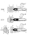
- Figures 1-3 illustrate schematically an injection moulding press 1 that includes an ejector rod 1a, a number (3) of ejector pins 1b, a moveable mould 1c and a fixed mould 1d.
- the moveable mould half 1c and the fixed mould half 1d define therebetween a cavity 1d whose shape conforms to the shape of a flat, injection moulded plastic element 3, said cavity including a cavity inlet if in the shape of an intake.
- This microstructure is normally a very complex structure. However, for the sake of ease of illustration of the present invention, an extremely simplified and enlarged embodiment of this microstructure is also shown in Figure 4, but not according to scale.
- microstructure that includes a first raised part 21, an intermediate cavity or hollow 22 and a second raised part 23.
- the matrix 2 is thus provided with a negative microstructure 2a on one surface thereof
- the matrix 2 has the form of a disc or a plate that has a flat undersurface 2b, normally a flat machined surface 2b, which rests on a flat supporting surface 1c' in the moveable mould half 1c.
- the matrix has a flat (or curved) surface 2b which is able to rest against a flat surface 1c' (or a complementary curved surface) on the mould half 1c, such that the matrix 2 will be able to withstand the pressure forces that are generated during the process of manufacture, for instance during an injection press-moulding process.
- Figure 5 is a cross-sectional view of part of a known matrix 2, taken through the raised parts 21 and 23 and the cavity 22.
- the matrix 2 can be produced by coating a surface with metal through, for example, a metal plating process, to provide a master that has a positive microstructure on one side.
- metal layer upon metal layer are built up on the microstructure surface part 5a of the master, such that a first metal layer will cover even a lowest point in the microstructure on said surface part 5a.
- Plating processes for applying layers of the thickness concerned in this respect are very time-consuming. Grinding of the surplus metal material 6a down to the plane 6 is also very time-consuming.
- a matrix 2 is produced with the aid of a master 5 that may be produced in the same way as the master 5 shown in Figure 5.
- the surface-carried positive microstructure 5a is covered with a thin wear-resistant first layer 7, shown in Figure 6.
- This thin wear-resistant first layer 7 shall present an outer first wear-resistant surface 7a.
- the expression "wear-resistant surface” is intended to mean a surface against which the hot, flowing plastic material shall be pressed and against which the plastic element 3 shall be formed prior to being removed from the mould halves 1c, 1d.
- the wear-resistant layer 7 that forms the first wear-resistant surface 7a will be sufficiently thin, for instance a thinness of 2 ⁇ m, for it to show a negative outer microstructure 2a that corresponds exactly to the positive microstructure 5a for the master 5.
- the first wear-resistant layer 7 may be comprised of a plastic composite or some other hard material, although it is assumed in the following description by way of illustration that this thin, first wear-resistant layer 7 is comprised of metal.
- the metal layer 7 can be applied with the aid of conventional techniques, for instance by sputtering or vapour deposition against a non-conductive master plate 5.
- Figure 6 is intended to show that this thin metal layer 7 can be applied to precisely cover the whole of the surface 5a allocated to the microstructure with a thin layer of metal.
- the inner or upper surface of the thin metal layer 7 in Figure 6 will present irregularities 7b that correspond substantially to the microstructure 5a.
- these irregularities 7b are filled in a second stage with a selected plastic composite 8'.
- the plastic mass used for this plastic composite 8' should be hot and will be sufficiently fluid to fill all cavities or hollows 22 and cover all raised parts 21, 23 and therewith provide a flat upper surface 8a.
- Figure 6 is intended to illustrate an embodiment in which a plastic composite 8' is applied to form a carrier element 8 in a manner such that a small proportion 8a' of the plastic composite will be located over the plane 6 and a contemplated flat surface 8a, wherewith the excess plastic material 8a' can now be easily removed by a mechanical planning process
- the matrix 2, in the form of a carrier element 8 and a thin first wear-resistant surface 7a, is lifted out of or away from the master unit 5 and mounted in the moveable mould half 1c with the surface 2b (6) in abutment with the surface 1c'.
- the plastic composite 8' that is used to form a carrier element 8 may conveniently be applied under pressure in a mould cavity in a manner such as to obviate the need of machining or mechanically working the rear side of the carrier element.
- a plastic composite 8' and a carrier element 8 formed therewith affords many adaptation possibilities. It is well known that different polymeric materials and mixtures thereof admixed with different fillers and mixtures thereof give different properties, and that selected curing processes and curing times influence the final properties of the plastic composite. This knowledge offers many different possibilities with respect to its application with a matrix in accordance with the invention.
- a plastic composite 8' may be chosen from a polymeric material that has been mixed with a filling material, such as quartz-filled, metal-filled or carbon-fibre or other fibre or particle-filled epoxy or silicone polymers.
- the plastic composite 8' and a carrier element 8 formed therefrom can be chosen to have a coefficient of linear expansion or a thermal conductivity and/or a heat capacity that is adapted to a chosen process and/or to the nature of the machine used.
- the plastic composite 8' may be chosen to cure in response to heat and/or through illumination with Uv-light. These curing possibilities may be conveniently utilised so as to enable the plastic composite to be adapted to give the requisite hardness and stiffness.
- the plastic composite used may be a bicomponent type.
- Figures 7 and 8 are intended to illustrate that when a plastic composite 8' chosen to form a carrier element 8 located beneath the hard metal layer 7 forming a first wear-resistant surface 7a has an adapted low thermal conductivity (e.g under 2W/m/°/K) and/or an adapted high heat capacity (obtained by having a preferably high specific heat capacity and/or a large mass), the plastic composite 8' and the carrier element 8 will function as a heat insulator against the mould half 1c, so that the plastic material pressed forwards in the machine can be kept hot for the length of time taken for it to flow to and fill the most distant parts of the mould in order to form the microstructure pattern 3a in the plastic element 3.
- an adapted low thermal conductivity e.g under 2W/m/°/K
- an adapted high heat capacity obtained by having a preferably high specific heat capacity and/or a large mass
- the matrix 2, shown in Figures 7 and 8 is coated with or has applied thereto a second wear-resistant layer 9 that provides a second wear-resistant surface 9a.
- This layer 9 is applied to the surface 8a of the carrier element 8 that faces away from the metal layer 7 and may consist of a hard-wearing layer and/or a heat-insulating layer.
- the second wear-resistant layer 9 shall present to the surface 1c' of the mould half 1c a low-friction wear surface 9a of high abrasive resistance, since the pressure between the matrix 2 and the mould half 1c is high during the casting or moulding process and thermal stresses tend to displace the matrix 2 relative to said mould half 1c.
- the second wear surface 9 may, in this case, conveniently comprise titanium nitride or diamond-like-carbon (DLC).
- DLC diamond-like-carbon
- the material used to form the second wear layer 9 may be the same material as that used to form the thin, first wear-resistant layer 7a, with a plastic carrier element 8 placed therebetween.
- the thin metal layer 7 can be applied by a sputtering process and/or by vapour deposition, or by a plating or cladding process.
- Figure 8 illustrates an alternative embodiment which includes an abrasion-resistant second wear layer 9, a carrier element 8 formed by a plastic composite 8' and a thin, first wear-resistant layer in the form of a metal layer 7, where a cavity or hollow 22 has the dimensions shown in Figure 4, whereas an adjacent hollow or cavity 24 is much deeper than said cavity 22.
- a carrier element 8 having a carrier surface 8b for the thin first wear-resistant layer 7 and/or said layer 7 may comprise a plastic composite 8' having a coefficient of linear expansion and/or a thermal conductivity and/or a heat capacity adapted to a chosen process and/or to the design of the moulding machine used.
- the coefficient of linear expansion is lower than 1 x 10 -5 /°K so that the moulded structure does not change shape too much when exposed to the extremes of temperature found in plastic element manufacturing processes.
- the carrier element 8 may also be comprised of a plastic composite that can be given different degrees of hardness, by applying different degrees of heat and/or by irradiation with UV-light.
- the carrier element 8 may also be comprised of a material that has a low thermal conductivity and a high heat-insulating and/or heat capacity in order to prevent it absorbing too much heat energy from the hot plastic mass.
- the carrier element 8 may also be reinforced with known means.
- the carrier element 8 may be strengthened with a further anti-wear layer 9 on the surface thereof that lies distal from the metalled surface 7.
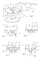
- the plastic composite 8' may be applied to a mould cavity 90 in the form of a casting matrix or mould 91 with the aid of an overpressure exerted by a plunger 92, so that the surface 8a of the carrier element will be made flat by the surface section 91 a of the mould 91.
- This flat surface 8a can now be applied directly to the support surface 1c' of the mould half 1c.
- the thickness of the layer 7 a basic rule is that the thickness will be sufficient to prevent a collapse or crack formation occurring during a chosen number of casting or moulding processes. This means, in practice, a thickness of 1-5 ⁇ m
- the thickness may range between 1 and 50 ⁇ m, and will preferably be less than 20 ⁇ m.
- the layer may have a thinness of about 0.1 ⁇ m, depending on the material from which the carrier element 8 is formed, among other things.
- the thickness of the wear layer 9 may be between 1 and 50 ⁇ m, preferably less than 20 ⁇ m.
- the depth variation of the microstructure 1a may vary between 0.1 and 1000 ⁇ m, and will preferably be above 100 ⁇ m.
- the matrix 2 is provided with means for improving the replication of its microstructure 2a on the plastic element 3.
- the matrix 2 in a known way is provided on one surface with a layer 7 having a negative surface structure 2a and against which negative surface structure 2a a positive surface structure 3a belonging to a plastic element 3 is formed.
- the manufacturing of the plastic element 3 occurs principally through the mould half 1c and 1d taking up a joined together position and thereby forming said mould cavity 1e.
- the mould halves 1c and 1d are heated in order to facilitate the distribution and the filling of the mould cavity 1e by a heated plastic mass (approximately 400°C).
- the mould halves 1c and 1d and the matrix 2 are given a considerably lower temperature than the plastic mass and there is a risk that a hot (say approximately 400°C) plastic mass does not manage to fill the mould cavity le and flow out to the edges before the plastic mass solidifies against the surface 2a of the matrix 2. Subsequently the plastic mass is cooled so that at least the surface structure 3a of the plastic element is solid (say approximately 140°C) and then the mould halves 1c and 1d are opened and the plastic element ejected (in accordance with figure 3).
- the method requires a rapid temperature change and the cycle times for the manufacture of plastic elements 3 are strongly dependent on the speed and the efficiency of this temperature changing.
- the present invention is based upon that a required heating shall take place in the surface structure belonging to the layer 7 of the matrix 2 or in a layer situated close to this layer and especially that the necessary heating should be able to be concentrated to the parts where a risk for a incomplete filling is specially imminent with increased production speed.
- the used mould halves 1c and 1d, and also a part of the matrix 2 shall through having a more or less constant application of cooling means be given a comparatively low temperature in order to be present as an available cooling capacity immediately after the end of a moulding process.
- a suitable temperature difference between the solidifying temperature of the plastic material and the temperature of the mould halves should be between 40 - 100°C, such as approximately 50 - 70°C, in an application in accordance with the present invention.
- the whole of the layer 7 of the matrix 2 or in any case one or more local parts thereof shall be preheated via an electrical production of heat to a suitable moulding temperature immediately before the commencement of the moulding process.
- the layer 7 is heated up by the hot plastic mass when this plastic mass is injected into the mould cavity.
- the injected plastic mass 1p will keep the layer 7 hot so that a complete filling will take place despite the cooling effect of the matrix layer 7.
- the injected plastic mass 1p will have been cooled down by the layer 7and it is within this region that a incomplete filling occurs because of an extremely thin plastic layer, a skin layer, solidifying against the layer 7 of the matrix 2. It is in order to eliminate the occurrence of such skin layers 1s that the present invention relates to a local heating of the layer 7 of the matrix 2 in at least the region 21b.
- the layer 21b of the matrix normally does not need to have a very high temperature from the local heating and a temperature around or something over the actual solidification temperature is normally sufficient.
- the invention can however offer a temperature for the region 21b of the layer 7 which can be up to an extremely high temperature, say over 200°C.
- the arrangement belonging to the matrix in accordance with the invention is further based upon the use of a heating means 4, in order to, in the first instance, for a short duration of time, supply said matrix 2 and/or the selected region (21b) with a requisite heat energy.
- the necessary cooling can take place through keeping the mould halves 1c and 1d constantly cold via a (not shown) cooling means.
- the invention can be considered such that immediately before, and preferably during, the moulding process the electrical heat energy should be supplied to form a thin heat layer between the matrix surface 2a and the mould half 1c in order to facilitate good filling of the mould by the hot plastic mass.
- the matrix surface 2a and the layer 7 are quickly cooled down to a temperature below the solidifying point for the plastic mass through the low temperature which is being selected to be in force on the mould halves rising up through the layer 7 and the hot plastic element 3 present in the mould cavity 1e. In this way, the cycle time for the manufacture of each such plastic element 3 is reduced.
- Figure 10 shows that the one connection wire 4a of the heating means 4 is connected to the outer peripheral edge 2b of the matrix 2 and the other connection 4b is connected to the central edge 2c of the matrix as connection points 2b' respectively 2c'.
- connection points 2b' and 2c' are connected to the layer 7 which can be electrically conducting or to one or more underlying layers such as 31, 41, 42 and 52 which can be electrically conducting or semi-conducting.
- the following description comprises for the sake of simplicity only the layer 7 and a number of layers belonging to the matrix situated close to this layer.
- Heating means 4 referred to in accordance with the invention is the supply of electrical heat energy to the whole or selected parts of the matrix 2 and directly or indirectly to the layer 7, and via a switching means (not shown) heat energy is supplied immediately before and during the injection moulding process in order to keep the walls of the matrix hot and thereby facilitate that the hot plastic mass flows out
- connection shown in figure 10 for manufacturing a circular disk 3 implies a higher current density and a higher heat emission from the surface part 21 a of the layer 7 adjacent the central edge of the hole 2c than within the peripheral edge 2b and the surface region 21b.
- Heating up of the part of the surface 21b is on the other hand necessary.
- a first possibility for this is offered by overheating the surface section 21a in the aid of an adapted heat supply to the surface section 21b when layer 7 is essentially evenly thick.
- Another possibility is to allocate different thicknesses to the layer 7 with a thinner layer across the direction of current in the surface section 21b than in the surface section 21a and with a thereof guaranteed increased heat development in the surface section 21b.
- said electrical heat energy is applied via or immediately next to the layer 7 of the negative surface structure 2a belonging to the matrix and figure 11 illustrates an embodiment where the electrical heat energy can be supplied only via the thin layer 7 of the surface structure 2a.
- the optimal thickness of the layer 7 depends on the selected manufacturing process, selected plastic material, design of the matrix, selected concentrated heat production within the selected partial regions and many other criteria. Practical experience shows that in many applications the thickness should be selected to be less than 20 ⁇ m, say 2 - 10 ⁇ m, or up to 5 ⁇ m.
- layer 7 is made of just one type of material then more heat will produced in the central part 2c while a lesser energy production will occur in the peripheral part 2b due to the differing current densities.
- Such an embodiment should possibly be especially suitable if the microstructure around the central edge 3c in the element 3 is sensitive to the moulding conditions and, therefore, in order to obtain a good replication capacity and mould filling, a higher temperature of the plastic mass and the matrix is required there than in the peripheral region.
- a suitable precondition for the present invention is furthermore, according to figure 11, that said layer 7 having the negative surface structure 2a and/or a layer 31 supporting this layer 7 consist(s) of an electrically conducting or electrically semi-conducting material.
- connection points 2b' and 2c' can be connected to just layer 7, just layer 31 or to both layers 7 and 31.
- the layer 31 can consist of an electrically conducting polymer.
- the layer 7 having the negative surface structure belonging to the matrix is preferably made of a material, such as nickel, with a resistivity of between 0,025 and 0,12 Ohms x mm 2 /m.
- the local heat production across the direction of the current flow can be regulated through locally changing the thickness (and consequently the cross-sectional area) of the layer 7, with a thinner layer of material where a higher heat production is required and a thicker layer of material where a lower heat production is required. Regard should paid to the current density occurring in the material to prevent it being damaged.
- Said layer 7 having the negative surface structure belonging to the matrix is, in figure 12, supported by a layer 41 with a resistivity of 0.03 Ohms x mm 2 /m or less.
- the thickness of the layer 41 should be selected depending on the relevant criteria, in the same way as for the layer 7. Practical experience shows that in many applications the thickness should be selected to be less than 20 ⁇ m, preferably thinner than 10 ⁇ m and advantageously up to 5 ⁇ m.
- the layer 41 can advantageously be made of gold, silver or the like.
- a further supporting layer 42 can be formed of a heat producing and/or supporting layer, where said supporting layer 42 can consist of a material with high resistivity.
- An electrically conducting polymer can also be used here.
- Figure 13 shows a layer 52 having a high resistivity intermediately positioned between two thin layers 41, 51 that each have a low resistivity.
- Figure 13 also shows that the layer 7 can be the same as the layer 7 according to figure 11, that the layer 41 can be the same as the layer 41 in figure 4 and that a supporting layer 42 can be formed from the further supporting layer 52. It is especially advantageous that the layer 52 can have different thicknesses (i.e. varying cross-sectional areas), thicker at sections which require low heat energy and thinner at sections which require higher heat energy.
- the voltage from the heating means 4 is connected to layers 41 and 51.
- the invention has a special application where the layer 7 having the negative surface structure 2a belonging to the matrix has the form of a microstructure 2a and this microstructure 2a is to be transferred to the plastic element 3 as a positive micro-related surface-structure 3a.
- this application it is especially important to allow the heat production to be adapted to be higher at some selected surface sections belonging to the matrix than at other surface sections in order to thereby increase the replication accuracy and degree of mould filling or mould filling capacity.
- Figure 14 shows a further embodiment of the present invention.
- the practical application here also requires dimensional variations within wide ranges.
- the thickness of the layer 7 should be selected to be less than 10 ⁇ m, say 2 - 8 ⁇ m.
- the layer 7 here consists of an up to 5 um thick titanium nitride which gives a hard surface 21a respectively 21b against the plastic element 3 and has good wear- and release characteristics.
- the layer 41 can consist of an up to 300 ⁇ m thick nickel layer that gives a hard coating and forms a support and carrier for the layer 7. Nickel is relatively cheap and can be considered to have acceptable electrical conductivity.
- the layer 61 should consist of a material with good electrical characteristics such as gold, silver, copper.
- the thickness of this layer should be thin, say less than 10 ⁇ m, for example 2 - 8 ⁇ m and preferably under 5 ⁇ m.
- the supporting layer 62 can be made of a polymer material which can be plated and which acts as a heat shield. These layers can be applied advantageously with known techniques such as surface deposition, plating, casting, spinning, spray painting or via vacuum deposition techniques such as sputtering or vaporisation.
Landscapes
- Engineering & Computer Science (AREA)
- Mechanical Engineering (AREA)
- Manufacturing & Machinery (AREA)
- Moulds For Moulding Plastics Or The Like (AREA)
- Shaping Of Tube Ends By Bending Or Straightening (AREA)
- Manufacturing Optical Record Carriers (AREA)
- Preparation Of Compounds By Using Micro-Organisms (AREA)
- Liquid Crystal (AREA)
- Casting Or Compression Moulding Of Plastics Or The Like (AREA)
Priority Applications (1)
| Application Number | Priority Date | Filing Date | Title |
|---|---|---|---|
| EP03101762A EP1358987A3 (en) | 1998-10-14 | 1999-10-14 | A replication matrix |
Applications Claiming Priority (5)
| Application Number | Priority Date | Filing Date | Title |
|---|---|---|---|
| SE9803507A SE512986C2 (sv) | 1998-10-14 | 1998-10-14 | Förfarande för att framställa en matris samt matris |
| SE9803507 | 1998-10-14 | ||
| SE9804621A SE9804621L (sv) | 1998-12-30 | 1998-12-30 | Arrangemang vid en maskin för en framställning av en plastdetalj |
| SE9804621 | 1998-12-30 | ||
| PCT/SE1999/001858 WO2000021728A1 (en) | 1998-10-14 | 1999-10-14 | A matrix and method of producing said matrix |
Related Child Applications (1)
| Application Number | Title | Priority Date | Filing Date |
|---|---|---|---|
| EP03101762A Division EP1358987A3 (en) | 1998-10-14 | 1999-10-14 | A replication matrix |
Publications (2)
| Publication Number | Publication Date |
|---|---|
| EP1121234A1 EP1121234A1 (en) | 2001-08-08 |
| EP1121234B1 true EP1121234B1 (en) | 2003-10-01 |
Family
ID=26663416
Family Applications (2)
| Application Number | Title | Priority Date | Filing Date |
|---|---|---|---|
| EP99970352A Expired - Lifetime EP1121234B1 (en) | 1998-10-14 | 1999-10-14 | A matrix and method of producing said matrix |
| EP03101762A Withdrawn EP1358987A3 (en) | 1998-10-14 | 1999-10-14 | A replication matrix |
Family Applications After (1)
| Application Number | Title | Priority Date | Filing Date |
|---|---|---|---|
| EP03101762A Withdrawn EP1358987A3 (en) | 1998-10-14 | 1999-10-14 | A replication matrix |
Country Status (7)
| Country | Link |
|---|---|
| US (3) | US6454970B1 (enExample) |
| EP (2) | EP1121234B1 (enExample) |
| JP (1) | JP4447168B2 (enExample) |
| AT (1) | ATE251017T1 (enExample) |
| AU (1) | AU1426200A (enExample) |
| DE (1) | DE69911802T2 (enExample) |
| WO (1) | WO2000021728A1 (enExample) |
Families Citing this family (92)
| Publication number | Priority date | Publication date | Assignee | Title |
|---|---|---|---|---|
| GB9808836D0 (en) * | 1998-04-27 | 1998-06-24 | Amersham Pharm Biotech Uk Ltd | Microfabricated apparatus for cell based assays |
| GB9809943D0 (en) * | 1998-05-08 | 1998-07-08 | Amersham Pharm Biotech Ab | Microfluidic device |
| DE69911802T2 (de) * | 1998-10-14 | 2004-07-29 | Gyros Ab | Form und verfahren zu deren herstellung |
| US7261859B2 (en) * | 1998-12-30 | 2007-08-28 | Gyros Ab | Microanalysis device |
| SE9901100D0 (sv) | 1999-03-24 | 1999-03-24 | Amersham Pharm Biotech Ab | Surface and tis manufacture and uses |
| DE19926181C1 (de) * | 1999-06-09 | 2000-12-14 | Inst Mikrotechnik Mainz Gmbh | Magazin für mikrostrukturierte Formteile und Verfahren zu dessen Herstellung |
| SE9904802D0 (sv) * | 1999-12-23 | 1999-12-23 | Amersham Pharm Biotech Ab | Microfluidic surfaces |
| SE0000300D0 (sv) | 2000-01-30 | 2000-01-30 | Amersham Pharm Biotech Ab | Microfluidic assembly, covering method for the manufacture of the assembly and the use of the assembly |
| SE0001790D0 (sv) * | 2000-05-12 | 2000-05-12 | Aamic Ab | Hydrophobic barrier |
| SE0004296D0 (sv) * | 2000-11-23 | 2000-11-23 | Gyros Ab | Device and method for the controlled heating in micro channel systems |
| US6653625B2 (en) * | 2001-03-19 | 2003-11-25 | Gyros Ab | Microfluidic system (MS) |
| US7429354B2 (en) | 2001-03-19 | 2008-09-30 | Gyros Patent Ab | Structural units that define fluidic functions |
| WO2002075312A1 (en) | 2001-03-19 | 2002-09-26 | Gyros Ab | Characterization of reaction variables |
| US6919058B2 (en) * | 2001-08-28 | 2005-07-19 | Gyros Ab | Retaining microfluidic microcavity and other microfluidic structures |
| US20050214442A1 (en) * | 2001-11-27 | 2005-09-29 | Anders Larsson | Surface and its manufacture and uses |
| US7238255B2 (en) * | 2001-12-31 | 2007-07-03 | Gyros Patent Ab | Microfluidic device and its manufacture |
| US7221783B2 (en) * | 2001-12-31 | 2007-05-22 | Gyros Patent Ab | Method and arrangement for reducing noise |
| US7459127B2 (en) | 2002-02-26 | 2008-12-02 | Siemens Healthcare Diagnostics Inc. | Method and apparatus for precise transfer and manipulation of fluids by centrifugal and/or capillary forces |
| WO2003082730A1 (en) * | 2002-03-31 | 2003-10-09 | Gyros Ab | Efficient mmicrofluidic devices |
| US6955738B2 (en) * | 2002-04-09 | 2005-10-18 | Gyros Ab | Microfluidic devices with new inner surfaces |
| US20050277195A1 (en) * | 2002-04-30 | 2005-12-15 | Gyros Ab | Integrated microfluidic device (ea) |
| JP4423189B2 (ja) * | 2002-05-31 | 2010-03-03 | ユィロス・パテント・アクチボラグ | 表面プラズモン共鳴に基づく検出装置 |
| US7125711B2 (en) | 2002-12-19 | 2006-10-24 | Bayer Healthcare Llc | Method and apparatus for splitting of specimens into multiple channels of a microfluidic device |
| US7094354B2 (en) | 2002-12-19 | 2006-08-22 | Bayer Healthcare Llc | Method and apparatus for separation of particles in a microfluidic device |
| WO2004067444A1 (en) | 2003-01-30 | 2004-08-12 | Gyros Ab | Inner walls of microfluidic devices |
| US20050042770A1 (en) * | 2003-05-23 | 2005-02-24 | Gyros Ab | Fluidic functions based on non-wettable surfaces |
| US7435381B2 (en) | 2003-05-29 | 2008-10-14 | Siemens Healthcare Diagnostics Inc. | Packaging of microfluidic devices |
| US7347617B2 (en) | 2003-08-19 | 2008-03-25 | Siemens Healthcare Diagnostics Inc. | Mixing in microfluidic devices |
| EP1660870A2 (en) * | 2003-08-26 | 2006-05-31 | Blueshift Biotechnologies, Inc. | Time dependent fluorescence measurements |
| US20050280811A1 (en) * | 2003-09-19 | 2005-12-22 | Donald Sandell | Grooved high density plate |
| WO2005028109A2 (en) * | 2003-09-19 | 2005-03-31 | Applera Corporation | Microplates useful for conducting thermocycled nucleotide amplification |
| US20050225751A1 (en) * | 2003-09-19 | 2005-10-13 | Donald Sandell | Two-piece high density plate |
| DE10344777B4 (de) * | 2003-09-26 | 2006-04-27 | Infineon Technologies Ag | Stempelvorrichtung für Softlithografie und Verfahren zu deren Herstellung |
| US7776272B2 (en) * | 2003-10-03 | 2010-08-17 | Gyros Patent Ab | Liquid router |
| US20050116387A1 (en) * | 2003-12-01 | 2005-06-02 | Davison Peter A. | Component packaging apparatus, systems, and methods |
| DE10359321A1 (de) * | 2003-12-17 | 2005-07-28 | Unaxis Balzers Ag | Glanzgradeinstellung |
| US20090010819A1 (en) * | 2004-01-17 | 2009-01-08 | Gyros Patent Ab | Versatile flow path |
| US8592219B2 (en) * | 2005-01-17 | 2013-11-26 | Gyros Patent Ab | Protecting agent |
| WO2005081801A2 (en) * | 2004-02-09 | 2005-09-09 | Blueshift Biotechnologies, Inc. | Methods and apparatus for scanning small sample volumes |
| TW201509943A (zh) * | 2004-03-30 | 2015-03-16 | Euro Celtique Sa | 含有小於25ppm14-羥可待因酮之羥可酮鹽酸鹽之組成物、醫藥劑型、延遲釋出口服劑型及醫藥上可以接受的包裝 |
| US7141378B2 (en) | 2004-07-02 | 2006-11-28 | Blueshift Biotechnologies, Inc. | Exploring fluorophore microenvironments |
| EP1849004A1 (en) * | 2005-01-17 | 2007-10-31 | Gyros Patent Ab | A versatile flow path |
| US8140745B2 (en) | 2005-09-09 | 2012-03-20 | The Invention Science Fund I, Llc | Data retrieval methods |
| US7770028B2 (en) * | 2005-09-09 | 2010-08-03 | Invention Science Fund 1, Llc | Limited use data storing device |
| US7907486B2 (en) | 2006-06-20 | 2011-03-15 | The Invention Science Fund I, Llc | Rotation responsive disk activation and deactivation mechanisms |
| US8099608B2 (en) | 2005-05-09 | 2012-01-17 | The Invention Science Fund I, Llc | Limited use data storing device |
| US7519980B2 (en) * | 2005-05-09 | 2009-04-14 | Searete Llc | Fluid mediated disk activation and deactivation mechanisms |
| US7565596B2 (en) | 2005-09-09 | 2009-07-21 | Searete Llc | Data recovery systems |
| US7512959B2 (en) * | 2005-05-09 | 2009-03-31 | Searete Llc | Rotation responsive disk activation and deactivation mechanisms |
| US8121016B2 (en) | 2005-05-09 | 2012-02-21 | The Invention Science Fund I, Llc | Rotation responsive disk activation and deactivation mechanisms |
| US8218262B2 (en) | 2005-05-09 | 2012-07-10 | The Invention Science Fund I, Llc | Method of manufacturing a limited use data storing device including structured data and primary and secondary read-support information |
| US7694316B2 (en) * | 2005-05-09 | 2010-04-06 | The Invention Science Fund I, Llc | Fluid mediated disk activation and deactivation mechanisms |
| US7748012B2 (en) * | 2005-05-09 | 2010-06-29 | Searete Llc | Method of manufacturing a limited use data storing device |
| US8462605B2 (en) | 2005-05-09 | 2013-06-11 | The Invention Science Fund I, Llc | Method of manufacturing a limited use data storing device |
| US7916592B2 (en) | 2005-05-09 | 2011-03-29 | The Invention Science Fund I, Llc | Fluid mediated disk activation and deactivation mechanisms |
| US7596073B2 (en) * | 2005-05-09 | 2009-09-29 | Searete Llc | Method and system for fluid mediated disk activation and deactivation |
| US9396752B2 (en) | 2005-08-05 | 2016-07-19 | Searete Llc | Memory device activation and deactivation |
| US7668068B2 (en) * | 2005-06-09 | 2010-02-23 | Searete Llc | Rotation responsive disk activation and deactivation mechanisms |
| US7668069B2 (en) * | 2005-05-09 | 2010-02-23 | Searete Llc | Limited use memory device with associated information |
| US20110181981A1 (en) * | 2005-05-09 | 2011-07-28 | Searete Llc, A Limited Liability Corporation Of The State Of Delaware | Method and system for rotational control of data storage devices |
| US8220014B2 (en) | 2005-05-09 | 2012-07-10 | The Invention Science Fund I, Llc | Modifiable memory devices having limited expected lifetime |
| US8159925B2 (en) | 2005-08-05 | 2012-04-17 | The Invention Science Fund I, Llc | Limited use memory device with associated information |
| US7916615B2 (en) | 2005-06-09 | 2011-03-29 | The Invention Science Fund I, Llc | Method and system for rotational control of data storage devices |
| US20070023976A1 (en) * | 2005-07-26 | 2007-02-01 | Asml Netherlands B.V. | Imprint lithography |
| US8264928B2 (en) | 2006-06-19 | 2012-09-11 | The Invention Science Fund I, Llc | Method and system for fluid mediated disk activation and deactivation |
| US8432777B2 (en) * | 2006-06-19 | 2013-04-30 | The Invention Science Fund I, Llc | Method and system for fluid mediated disk activation and deactivation |
| SE0700424L (sv) | 2007-02-21 | 2008-05-20 | Gyros Patent Ab | Förfarande för blandning av alikvoter i en mikrokanalstruktur |
| FR2930244B1 (fr) * | 2008-04-18 | 2011-06-24 | Commissariat Energie Atomique | Procede de preparation d'un film polymerique presentant en surface des motifs nanometriques et microstructure dans son epaisseur sur tout ou partie de celui-ci selon un systeme particulier |
| DE102008046673A1 (de) * | 2008-09-10 | 2010-03-11 | Grohe Ag | Verbundkörper |
| DE102009051598B4 (de) | 2009-11-02 | 2022-10-06 | Vereinigung zur Förderung des Instituts für Kunststoffverarbeitung in Industrie und Handwerk an der Rhein.-Westf. Technischen Hochschule Aachen e.V. | Verfahren zur Herstellung von Vorrichtungen mit Mikrostrukturen aus Kunststoff mittels Verstreckung zum Zwecke der Selbstreinigung, derartige Vorrichtungen und deren Verwendung |
| WO2012138701A1 (en) | 2011-04-06 | 2012-10-11 | Ortho-Clinical Diagnostics, Inc | Assay device having rhombus-shaped projections |
| CA2802645C (en) | 2012-01-20 | 2020-08-11 | Ortho-Clinical Diagnostics, Inc. | Assay device having controllable sample size |
| CN103217519B (zh) | 2012-01-20 | 2017-06-20 | 奥索临床诊断有限公司 | 具有多个试剂池的测定装置 |
| CN103212455B (zh) | 2012-01-20 | 2016-12-28 | 奥索临床诊断有限公司 | 在角附近具有均匀流的测定装置 |
| WO2013109821A1 (en) | 2012-01-20 | 2013-07-25 | Ortho-Clinical Diagnostics, Inc. | Assay device having multiplexing |
| KR20130085993A (ko) | 2012-01-20 | 2013-07-30 | 오르토-클리니칼 다이아그노스틱스, 인코포레이티드 | 분석 장치를 통한 유체 유동의 제어 |
| WO2013146985A1 (ja) * | 2012-03-30 | 2013-10-03 | コニカミノルタアドバンストレイヤー株式会社 | 成形用金型及びその製造方法 |
| DE102012103120B4 (de) * | 2012-04-11 | 2025-04-30 | Günther Heisskanaltechnik Gmbh | Werkzeugeinsatz mit Schichtheizung, Formplatte mit einem solchen Werkzeugeinsatz und Verfahren zum Betrieb eines solchen Werkzeugeinsatzes |
| TWI456196B (zh) | 2012-04-24 | 2014-10-11 | Ind Tech Res Inst | 檢體免疫分析檢測裝置 |
| CA2818332C (en) | 2012-06-12 | 2021-07-20 | Ortho-Clinical Diagnostics, Inc. | Lateral flow assay devices for use in clinical diagnostic apparatus and configuration of clinical diagnostic apparatus for same |
| JP6359263B2 (ja) | 2012-11-15 | 2018-07-18 | オーソ・クリニカル・ダイアグノスティックス・インコーポレーテッド | 流れモニタリングに基づく、側方流動アッセイ装置の品質/プロセス制御 |
| CN110412265B (zh) | 2012-11-15 | 2023-04-11 | 奥索临床诊断有限公司 | 使用反应时间的校准分析 |
| CA2841692C (en) | 2013-02-12 | 2023-08-22 | Zhong Ding | Reagent zone deposition pattern |
| EP2778679B1 (en) | 2013-03-15 | 2017-09-27 | Ortho-Clinical Diagnostics, Inc. | Rotable disk-shaped fluid sample collection device |
| EP2777499B1 (en) | 2013-03-15 | 2015-09-16 | Ortho-Clinical Diagnostics Inc | Rotatable fluid sample collection device |
| WO2015085181A1 (en) | 2013-12-06 | 2015-06-11 | Ortho Clinical Diagnostics, Inc. | Assay device having a wash port |
| US10031085B2 (en) | 2014-07-24 | 2018-07-24 | Ortho-Clinical Diagnostics, Inc. | Point of care analytical processing system |
| US11033896B2 (en) | 2014-08-08 | 2021-06-15 | Ortho-Clinical Diagnostics, Inc. | Lateral-flow assay device with filtration flow control |
| US10073091B2 (en) | 2014-08-08 | 2018-09-11 | Ortho-Clinical Diagnostics, Inc. | Lateral flow assay device |
| US10071373B2 (en) | 2014-08-08 | 2018-09-11 | Ortho-Clinical Diagnostics, Inc. | Lateral-flow assay device having flow constrictions |
| CN107636460A (zh) | 2015-05-19 | 2018-01-26 | 奥索临床诊断有限公司 | 改善测定装置中液体样品流动的方法 |
| DE102016100288A1 (de) * | 2016-01-11 | 2017-07-13 | Dr. Ing. H.C. F. Porsche Aktiengesellschaft | Farbkonstante Oberflächen |
Family Cites Families (27)
| Publication number | Priority date | Publication date | Assignee | Title |
|---|---|---|---|---|
| JPS5835742A (ja) * | 1981-08-21 | 1983-03-02 | Victor Co Of Japan Ltd | 情報記録媒体円盤の製作に用いられるスタンパの製作法 |
| JPS61165843A (ja) * | 1985-01-14 | 1986-07-26 | Tdk Corp | 情報記録媒体基板成形用電鋳型 |
| JPH0630174B2 (ja) * | 1985-03-19 | 1994-04-20 | 松下電器産業株式会社 | 金属スタンパの製造方法 |
| DE3537483C1 (de) * | 1985-10-22 | 1986-12-04 | Kernforschungszentrum Karlsruhe Gmbh, 7500 Karlsruhe | Verfahren zum Herstellen einer Vielzahl plattenfoermiger Mikrostrukturkoerper aus Metall |
| NL8503234A (nl) * | 1985-11-25 | 1987-06-16 | Philips Nv | Matrijs. |
| JPS62189645A (ja) * | 1986-02-17 | 1987-08-19 | Fujitsu Ltd | 光デイスク転写型の製造方法 |
| JPS62264461A (ja) * | 1986-05-13 | 1987-11-17 | Victor Co Of Japan Ltd | 情報信号記録担体用金型の製造法 |
| JPS63112842A (ja) * | 1986-10-28 | 1988-05-17 | Seiko Epson Corp | 光デイスク基板複製用スタンバ−の製造方法 |
| DE3725231A1 (de) * | 1987-07-30 | 1989-02-09 | Philips & Du Pont Optical | Verfahren zur herstellung und hinterfuetterung eines galvanos |
| US4793953A (en) * | 1987-10-16 | 1988-12-27 | Galic/Maus Ventures | Mold for optical thermoplastic high-pressure molding |
| JPH01142077A (ja) * | 1987-11-27 | 1989-06-02 | Toppan Printing Co Ltd | スタンパーの保存方法 |
| JPH02172041A (ja) * | 1988-12-23 | 1990-07-03 | Hitachi Ltd | 光デイスク用スタンパの作製方法 |
| JPH02215513A (ja) * | 1989-02-16 | 1990-08-28 | Ricoh Co Ltd | 精密金型による成形装置 |
| US5071597A (en) * | 1989-06-02 | 1991-12-10 | American Bank Note Holographics, Inc. | Plastic molding of articles including a hologram or other microstructure |
| JPH03278337A (ja) * | 1990-03-27 | 1991-12-10 | Nikon Corp | スタンパの製造方法 |
| DE4010669C1 (enExample) | 1990-04-03 | 1991-04-11 | Kernforschungszentrum Karlsruhe Gmbh, 7500 Karlsruhe, De | |
| JPH04139635A (ja) * | 1990-09-29 | 1992-05-13 | Toppan Printing Co Ltd | 光ディスク用スタンパー |
| CA2056307C (en) * | 1990-11-28 | 1997-09-16 | Hitoshi Isono | Method of manufacturing a stamper |
| JPH05116182A (ja) * | 1991-07-10 | 1993-05-14 | Ebara Corp | プラスチツク成形型 |
| US5390412A (en) * | 1993-04-08 | 1995-02-21 | Gregoire; George D. | Method for making printed circuit boards |
| US5512219A (en) * | 1994-06-03 | 1996-04-30 | Reflexite Corporation | Method of casting a microstructure sheet having an array of prism elements using a reusable polycarbonate mold |
| JP3150850B2 (ja) * | 1994-07-08 | 2001-03-26 | シャープ株式会社 | 光磁気ディスク原盤の製造方法 |
| JPH0890624A (ja) * | 1994-09-27 | 1996-04-09 | Meiki Co Ltd | ディスク基板成形用金型 |
| US5630902A (en) | 1994-12-30 | 1997-05-20 | Honeywell Inc. | Apparatus for use in high fidelty replication of diffractive optical elements |
| GB9601289D0 (en) * | 1996-01-23 | 1996-03-27 | Nimbus Manufacturing Uk Limite | Manufacture of optical data storage disc |
| JPH1034655A (ja) * | 1996-07-18 | 1998-02-10 | Taiho Kogyo Kk | 光学式情報記録媒体成形用金型およびその金型を用いた光学式情報記録媒体の成形方法 |
| DE69911802T2 (de) * | 1998-10-14 | 2004-07-29 | Gyros Ab | Form und verfahren zu deren herstellung |
-
1999
- 1999-10-14 DE DE69911802T patent/DE69911802T2/de not_active Expired - Lifetime
- 1999-10-14 JP JP2000575672A patent/JP4447168B2/ja not_active Expired - Lifetime
- 1999-10-14 AU AU14262/00A patent/AU1426200A/en not_active Abandoned
- 1999-10-14 WO PCT/SE1999/001858 patent/WO2000021728A1/en not_active Ceased
- 1999-10-14 AT AT99970352T patent/ATE251017T1/de not_active IP Right Cessation
- 1999-10-14 EP EP99970352A patent/EP1121234B1/en not_active Expired - Lifetime
- 1999-10-14 EP EP03101762A patent/EP1358987A3/en not_active Withdrawn
- 1999-10-14 US US09/554,530 patent/US6454970B1/en not_active Expired - Lifetime
-
2002
- 2002-08-02 US US10/211,185 patent/US6884370B2/en not_active Expired - Lifetime
-
2004
- 2004-12-02 US US11/001,830 patent/US7182890B2/en not_active Expired - Lifetime
Also Published As
| Publication number | Publication date |
|---|---|
| EP1358987A3 (en) | 2004-03-03 |
| US20030047823A1 (en) | 2003-03-13 |
| US7182890B2 (en) | 2007-02-27 |
| EP1121234A1 (en) | 2001-08-08 |
| WO2000021728A1 (en) | 2000-04-20 |
| US20050151051A1 (en) | 2005-07-14 |
| JP4447168B2 (ja) | 2010-04-07 |
| ATE251017T1 (de) | 2003-10-15 |
| DE69911802D1 (de) | 2003-11-06 |
| US6454970B1 (en) | 2002-09-24 |
| US6884370B2 (en) | 2005-04-26 |
| DE69911802T2 (de) | 2004-07-29 |
| AU1426200A (en) | 2000-05-01 |
| JP2002527255A (ja) | 2002-08-27 |
| EP1358987A2 (en) | 2003-11-05 |
Similar Documents
| Publication | Publication Date | Title |
|---|---|---|
| EP1121234B1 (en) | A matrix and method of producing said matrix | |
| EP2119549B1 (en) | Resin molding apparatus | |
| EP1212181B1 (en) | A method for the manufacturing of a matrix and a matrix manufactured according to said method | |
| EP0536872B1 (en) | Roll stamper for forming a base for information recording medium and apparatus using the roll stamper | |
| EP0844058A1 (en) | Mold for making disc substrate, process for producing mold and disc substrate | |
| JP3023618B2 (ja) | 連続鋳造用鋳型及びその製造方法 | |
| JP5360679B2 (ja) | 射出成形用の熱制御金型及びその製造方法 | |
| JP2010188701A (ja) | 樹脂スタンパー成形用金型、及びこれを用いた樹脂スタンパーの製造方法 | |
| JP3550461B2 (ja) | プラスチック成形方法並びに光ディスクの製造方法 | |
| JP4016278B2 (ja) | 成形型および成形品の製造方法 | |
| JP2004025647A (ja) | 入れ子、金型及びこれらの製造方法 | |
| JPH02279311A (ja) | 成形型の製造法 | |
| JPH05205322A (ja) | 情報記録媒体用基板シートの成形用ロールスタンパー及びそれを用いた情報記録媒体用基板の製造装置 | |
| JPH03114709A (ja) | デイスク用金型 | |
| WO1994020288A1 (en) | Mould for manufacturing disc-shaped information carriers | |
| JP2008221783A (ja) | プラスチック成形品の射出成形用断熱スタンパ及びその製造方法 | |
| JP3087136B2 (ja) | スタンパ原盤 | |
| JP3087137B2 (ja) | スタンパ原盤 | |
| JP2009242141A (ja) | 金型の再生方法及び再生金型 | |
| JPH10277699A (ja) | 金型および金型製造方法、ならびに、母型形成方法、電鋳品製造方法 | |
| KR19990087217A (ko) | 디스크기판 성형용 금형과 그 제조방법 및 금형장치 | |
| JP2009190312A (ja) | 樹脂成形品の製造方法及び成形型並びに外観部材 | |
| JPH0790669A (ja) | 成形用スタンパ及び成形用スタンパの製造方法 | |
| JPH02137916A (ja) | スタンパの製造方法 | |
| JPH0516192A (ja) | 射出成形用スタンパー |
Legal Events
| Date | Code | Title | Description |
|---|---|---|---|
| PUAI | Public reference made under article 153(3) epc to a published international application that has entered the european phase |
Free format text: ORIGINAL CODE: 0009012 |
|
| 17P | Request for examination filed |
Effective date: 20010512 |
|
| AK | Designated contracting states |
Kind code of ref document: A1 Designated state(s): AT BE CH CY DE DK ES FI FR GB GR IE IT LI LU |
|
| 17Q | First examination report despatched |
Effective date: 20011129 |
|
| GRAH | Despatch of communication of intention to grant a patent |
Free format text: ORIGINAL CODE: EPIDOS IGRA |
|
| GRAS | Grant fee paid |
Free format text: ORIGINAL CODE: EPIDOSNIGR3 |
|
| GRAA | (expected) grant |
Free format text: ORIGINAL CODE: 0009210 |
|
| RAP1 | Party data changed (applicant data changed or rights of an application transferred) |
Owner name: AMIC AB Owner name: GYROS AB |
|
| AK | Designated contracting states |
Kind code of ref document: B1 Designated state(s): AT BE CH CY DE DK ES FI FR GB GR IE IT LI LU MC NL PT SE |
|
| PG25 | Lapsed in a contracting state [announced via postgrant information from national office to epo] |
Ref country code: IT Free format text: LAPSE BECAUSE OF FAILURE TO SUBMIT A TRANSLATION OF THE DESCRIPTION OR TO PAY THE FEE WITHIN THE PRESCRIBED TIME-LIMIT;WARNING: LAPSES OF ITALIAN PATENTS WITH EFFECTIVE DATE BEFORE 2007 MAY HAVE OCCURRED AT ANY TIME BEFORE 2007. THE CORRECT EFFECTIVE DATE MAY BE DIFFERENT FROM THE ONE RECORDED. Effective date: 20031001 Ref country code: FI Free format text: LAPSE BECAUSE OF FAILURE TO SUBMIT A TRANSLATION OF THE DESCRIPTION OR TO PAY THE FEE WITHIN THE PRESCRIBED TIME-LIMIT Effective date: 20031001 Ref country code: BE Free format text: LAPSE BECAUSE OF FAILURE TO SUBMIT A TRANSLATION OF THE DESCRIPTION OR TO PAY THE FEE WITHIN THE PRESCRIBED TIME-LIMIT Effective date: 20031001 Ref country code: AT Free format text: LAPSE BECAUSE OF FAILURE TO SUBMIT A TRANSLATION OF THE DESCRIPTION OR TO PAY THE FEE WITHIN THE PRESCRIBED TIME-LIMIT Effective date: 20031001 |
|
| REG | Reference to a national code |
Ref country code: GB Ref legal event code: FG4D |
|
| PG25 | Lapsed in a contracting state [announced via postgrant information from national office to epo] |
Ref country code: LU Free format text: LAPSE BECAUSE OF NON-PAYMENT OF DUE FEES Effective date: 20031014 Ref country code: IE Free format text: LAPSE BECAUSE OF NON-PAYMENT OF DUE FEES Effective date: 20031014 Ref country code: CY Free format text: LAPSE BECAUSE OF FAILURE TO SUBMIT A TRANSLATION OF THE DESCRIPTION OR TO PAY THE FEE WITHIN THE PRESCRIBED TIME-LIMIT Effective date: 20031014 |
|
| REG | Reference to a national code |
Ref country code: CH Ref legal event code: EP |
|
| PGFP | Annual fee paid to national office [announced via postgrant information from national office to epo] |
Ref country code: NL Payment date: 20031027 Year of fee payment: 5 |
|
| PGFP | Annual fee paid to national office [announced via postgrant information from national office to epo] |
Ref country code: SE Payment date: 20031028 Year of fee payment: 5 |
|
| REG | Reference to a national code |
Ref country code: IE Ref legal event code: FG4D |
|
| PG25 | Lapsed in a contracting state [announced via postgrant information from national office to epo] |
Ref country code: MC Free format text: LAPSE BECAUSE OF NON-PAYMENT OF DUE FEES Effective date: 20031031 |
|
| REF | Corresponds to: |
Ref document number: 69911802 Country of ref document: DE Date of ref document: 20031106 Kind code of ref document: P |
|
| PG25 | Lapsed in a contracting state [announced via postgrant information from national office to epo] |
Ref country code: GR Free format text: LAPSE BECAUSE OF FAILURE TO SUBMIT A TRANSLATION OF THE DESCRIPTION OR TO PAY THE FEE WITHIN THE PRESCRIBED TIME-LIMIT Effective date: 20040101 Ref country code: DK Free format text: LAPSE BECAUSE OF FAILURE TO SUBMIT A TRANSLATION OF THE DESCRIPTION OR TO PAY THE FEE WITHIN THE PRESCRIBED TIME-LIMIT Effective date: 20040101 |
|
| PG25 | Lapsed in a contracting state [announced via postgrant information from national office to epo] |
Ref country code: ES Free format text: LAPSE BECAUSE OF FAILURE TO SUBMIT A TRANSLATION OF THE DESCRIPTION OR TO PAY THE FEE WITHIN THE PRESCRIBED TIME-LIMIT Effective date: 20040112 |
|
| REG | Reference to a national code |
Ref country code: SE Ref legal event code: TRGR |
|
| REG | Reference to a national code |
Ref country code: CH Ref legal event code: NV Representative=s name: ISLER & PEDRAZZINI AG |
|
| ET | Fr: translation filed | ||
| REG | Reference to a national code |
Ref country code: IE Ref legal event code: MM4A |
|
| PLBE | No opposition filed within time limit |
Free format text: ORIGINAL CODE: 0009261 |
|
| STAA | Information on the status of an ep patent application or granted ep patent |
Free format text: STATUS: NO OPPOSITION FILED WITHIN TIME LIMIT |
|
| 26N | No opposition filed |
Effective date: 20040702 |
|
| PG25 | Lapsed in a contracting state [announced via postgrant information from national office to epo] |
Ref country code: SE Free format text: LAPSE BECAUSE OF NON-PAYMENT OF DUE FEES Effective date: 20041015 |
|
| PG25 | Lapsed in a contracting state [announced via postgrant information from national office to epo] |
Ref country code: NL Free format text: LAPSE BECAUSE OF NON-PAYMENT OF DUE FEES Effective date: 20050501 |
|
| EUG | Se: european patent has lapsed | ||
| NLV4 | Nl: lapsed or anulled due to non-payment of the annual fee |
Effective date: 20050501 |
|
| REG | Reference to a national code |
Ref country code: CH Ref legal event code: PUEA Owner name: AMIC AB Free format text: AMIC AB#UPPSALA SCIENCE PARK#751 83 UPPSALA (SE) $ NORADA HOLDING AB#BOX 5845#102 48 STOCKHOLM (SE) -TRANSFER TO- AMIC AB#UPPSALA SCIENCE PARK#751 83 UPPSALA (SE) $ GYROS PATENT AB#UPPSALA SCIENCE PARK#751 83 UPPSALA (SE) Ref country code: CH Ref legal event code: PFA Owner name: AMIC AB Free format text: GYROS AB#UPPSALA SCIENCE PARK#751 83 UPPSALA (SE) $ AMIC AB#UPPSALA SCIENCE PARK#751 83 UPPSALA (SE) -TRANSFER TO- AMIC AB#UPPSALA SCIENCE PARK#751 83 UPPSALA (SE) $ NORADA HOLDING AB#BOX 5845#102 48 STOCKHOLM (SE) |
|
| REG | Reference to a national code |
Ref country code: GB Ref legal event code: 732E |
|
| REG | Reference to a national code |
Ref country code: FR Ref legal event code: TQ Ref country code: FR Ref legal event code: CD Ref country code: FR Ref legal event code: CA |
|
| REG | Reference to a national code |
Ref country code: CH Ref legal event code: PCAR Free format text: ISLER & PEDRAZZINI AG;POSTFACH 1772;8027 ZUERICH (CH) |
|
| PG25 | Lapsed in a contracting state [announced via postgrant information from national office to epo] |
Ref country code: PT Free format text: LAPSE BECAUSE OF NON-PAYMENT OF DUE FEES Effective date: 20040301 |
|
| REG | Reference to a national code |
Ref country code: FR Ref legal event code: PLFP Year of fee payment: 17 |
|
| REG | Reference to a national code |
Ref country code: FR Ref legal event code: PLFP Year of fee payment: 18 |
|
| REG | Reference to a national code |
Ref country code: FR Ref legal event code: PLFP Year of fee payment: 19 |
|
| REG | Reference to a national code |
Ref country code: FR Ref legal event code: PLFP Year of fee payment: 20 |
|
| PGFP | Annual fee paid to national office [announced via postgrant information from national office to epo] |
Ref country code: DE Payment date: 20181019 Year of fee payment: 20 |
|
| PGFP | Annual fee paid to national office [announced via postgrant information from national office to epo] |
Ref country code: FR Payment date: 20181022 Year of fee payment: 20 Ref country code: CH Payment date: 20181018 Year of fee payment: 20 Ref country code: GB Payment date: 20181017 Year of fee payment: 20 |
|
| REG | Reference to a national code |
Ref country code: DE Ref legal event code: R071 Ref document number: 69911802 Country of ref document: DE |
|
| REG | Reference to a national code |
Ref country code: CH Ref legal event code: PL |
|
| REG | Reference to a national code |
Ref country code: GB Ref legal event code: PE20 Expiry date: 20191013 |
|
| PG25 | Lapsed in a contracting state [announced via postgrant information from national office to epo] |
Ref country code: GB Free format text: LAPSE BECAUSE OF EXPIRATION OF PROTECTION Effective date: 20191013 |