EP1120746B1 - Kalibrierungssystem, Zielgerät und Kalibrierungsverfahren - Google Patents
Kalibrierungssystem, Zielgerät und Kalibrierungsverfahren Download PDFInfo
- Publication number
- EP1120746B1 EP1120746B1 EP01101811.6A EP01101811A EP1120746B1 EP 1120746 B1 EP1120746 B1 EP 1120746B1 EP 01101811 A EP01101811 A EP 01101811A EP 1120746 B1 EP1120746 B1 EP 1120746B1
- Authority
- EP
- European Patent Office
- Prior art keywords
- target apparatus
- target
- calibration
- camera
- vehicle
- Prior art date
- Legal status (The legal status is an assumption and is not a legal conclusion. Google has not performed a legal analysis and makes no representation as to the accuracy of the status listed.)
- Expired - Lifetime
Links
Images


Classifications
-
- B—PERFORMING OPERATIONS; TRANSPORTING
- B60—VEHICLES IN GENERAL
- B60R—VEHICLES, VEHICLE FITTINGS, OR VEHICLE PARTS, NOT OTHERWISE PROVIDED FOR
- B60R1/00—Optical viewing arrangements; Real-time viewing arrangements for drivers or passengers using optical image capturing systems, e.g. cameras or video systems specially adapted for use in or on vehicles
-
- G—PHYSICS
- G06—COMPUTING; CALCULATING OR COUNTING
- G06T—IMAGE DATA PROCESSING OR GENERATION, IN GENERAL
- G06T7/00—Image analysis
- G06T7/80—Analysis of captured images to determine intrinsic or extrinsic camera parameters, i.e. camera calibration
Definitions
- the present invention relates to calibration for calculating the position, orientation and the like of a camera. More specifically, the present invention relates to the technology of calibrating in a simple manner a camera mounted on a mobile object with high precision.
- a system that monitors the surroundings of a vehicle by means of a camera mounted thereon.
- a plurality of cameras are generally mounted on the vehicle so as to display a captured image on a monitor mounted inside the vehicle.
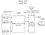
- Fig. 23 is a block diagram showing the structure of a conventional vehicle surrounding monitoring system (Japanese Laid-Open Publication No. 3-99952 ).
- an image converting section 1202 receives the respective images from a plurality of cameras 1201 mounted on the vehicle to produce a synthesized image as viewed from a virtual view point by perspective transformation.
- An image display portion 1203 displays the synthesized image on a TV monitor 1204 installed at, e.g., the driver's seat.
- the virtual view point is oriented downward at the upper central position of the vehicle, the driver can instantly see the situations at and around the vehicle from the TV monitor 1204, resulting in improved safety of the driving.
- the aforementioned monitoring system joins a plurality of camera images into a single image. In order to avoid any displacement at each boundary between the joined images, it is necessary to calculate in advance the orientation and position of each camera accurately. This calculation is referred to as camera calibration.
- a known calibration method feature points each having a known coordinate position in a prescribed coordinate system are captured with respective cameras in order to produce a set of data having the coordinates of each feature point on the camera image mapped with its actual spatial coordinates, i.e., calibration data. Calibration is conducted using the calibration data thus produced. Since this calibration method is described in detail in, e.g., Matsuyama et al., "Computer Vision: Gijyutsu Hyouron To Syourai Tenbou (Technical Review and Future Outlook)" (Shin-gijyutsu Communications, pp. 37-53, June 1998 ), description thereof is herein omitted.
- camera calibration technology of calibrating a visual sensor system of a transfer line by means of a special jig (disclosed in Japanese Publication for Opposition No. 7-90494 ); and technology of obtaining an installation error of fixed three-dimensional visual means in a robot coordinate system in a robot handling apparatus (disclosed in Japanese Publication for Opposition No. 7-27408 ).
- a camera calibration system for lane recognition and object detection is disclosed in Ernst et al., "Camera calibration for lane and obstacle detection” INTELLIGENT TRANSPORTATION SYSTEMS, 1999 .
- a calibration field is painted on a piece of road in order to enable an accurate 3D world reconstruction from a given 2D image of road scenes.
- Representative points, the so-called POIS (points of interest) are identified in the images.
- the origin of the system of world coordinates is the centre of the vehicles rear axle projected on the ground.
- the calibration of a camera can only be preformed as accurately as the camera mounted on the vehicle can be positioned on the calibration field.
- the positional relation between the mobile object and the target apparatus can be fixed to the prescribed relation by the positioning means.
- the mobile object need no longer be accurately positioned for camera calibration. Accordingly, calibration of the camera mounted on the mobile object is simplified.
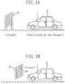
- Figs. 1A and 1B are diagrams conceptually showing a technical idea of the present invention.
- a vehicle 2 having a camera 1 mounted thereon is positioned on the ground, and a target apparatus 3 for calibration is fixed to the ground.
- the positional relation between the vehicle 2 and the target apparatus 3 is set by means of the ground.
- the vehicle 2 In the case of Fig. 1A , the vehicle 2 must be positioned on the ground with precision on the order of several millimeters in order to realize high-precision calibration, but in practice, this is extremely difficult. Moreover, the vehicle 2 must be moved to the installation location of the target apparatus 3 upon every calibration.
- the target apparatus 3 is directly fixed to the vehicle 2 as shown in Fig. 1B , rather than by means of the ground.
- the vehicle 2 need no longer be positioned with precision on the order of several millimeters, nor is the location for conducting calibration limited, thereby allowing implementation of simple calibration.
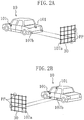
- Figs. 2A and 2B are diagrams showing the structure of a calibration system according to the first embodiment of the present invention.
- a vehicle 10 as a mobile object having cameras 101 mounted thereon and a target apparatus 30 for calibrating the cameras 101 are physically fixed to each other with joint means 107a, 107b serving as positioning means.
- Fig. 2A shows the target apparatus 30 being joined from the rear of the vehicle 10
- Fig. 2B shows the target apparatus 30 being joined from the side of the vehicle 10.
- the joint means 107a at the target apparatus 30 are, e.g., threaded projections
- the joint means 107b at the vehicle 10 are, e.g., tapped holes.
- the target apparatus 30 has feature points PP that are required to adjust the cameras 101.
- the feature points PP are provided by the intersections of a lattice structure formed by rods of plastic, wood or other materials.
- the feature points PP may be provided in any form, like being directly drawn on a plate-like material, as long as their positions can be specified.
- Calibration of the cameras 101 is conducted with the vehicle 10 and the target apparatus 30 being fixedly joined by the joint means 107a, 107b. Moreover, according to the structure of Figs. 2A and 2B , independent target apparatuses 30 need not be separately produced in order to cal ibrate the cameras 101 mounted at a plurality of positions. In other words, the same target apparatus 30 can be used in common.
- joint means for physically fixing the vehicle 10 and the target apparatus 30 to each other are not specifically limited to the combination of threaded projection and tapped hole, and various structures are possible.
- a hole may be formed in advance in the vehicle 10 as a joint means so as to receive a rod-like joint means provided at the target apparatus 30.
- a fixing member as a joint means may be provided only on the target apparatus 30.
- the target apparatus 30 is fixed to the vehicle 10 by, e.g., fitting the fixing member into a portion of the vehicle 10.
- Fig. 3 is a diagram showing an example of the structure using such fixing members.
- pinching members are used as joint means 107A.
- the target apparatus 30 is physically fixed to the vehicle 10 by pinching the rear bumper of the vehicle 10 with the pinching members.
- a special mechanism need not be provided on the vehicle 10, whereby external appearance of the vehicle 10 is not degraded. Note that marking the pinch positions in advance simplifies the operation of fixing the target apparatus 30.
- the fixing member (s) may be provided at the vehicle 10 in order to fix the target apparatus 30.
- the positional adjustment means 104 as shown in Fig. 4 includes a mechanism 104a capable of being finely adjusted in the vertical direction with a screw, and a mechanism 104b capable of being adjusted in position in the four directions (front, rear, right and left) with a wheel.
- the positional adjustment means 104 preferably has a fixing member for fixing the movement of the mechanisms 104a, 104b.
- this fixing member is merely required from the standpoint of preventing the positional displacement of the target apparatus 30 with respect to the ground.
- calibration of the cameras 101 can be carried out as long as the joint means can maintain a constant positional relation between the vehicle 10 and the target apparatus 30.
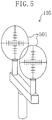
- a scope means 105 as shown in Fig. 5 is used in the present embodiment.
- the scope means 105 enables the operator to see if the vehicle 10 and the target apparatus 30 have a prescribed positional relation or not.
- two vertically and horizontally graduated circular glasses 501 are mounted at a prescribed distance from each other. Provision of the scope means 105 on the target apparatus 30 facilitates positional adjustment of the target apparatus 30.
- Fig. 6 is a diagram showing an example of the structure of a calibration system using the target apparatus 30 having the positional adjustment means 104 of Fig. 4 and the scope means 105 of Fig. 5 .
- the positional adjustment means 104, scope means 105 and joint means 107a, 107b form a positioning means according to the present invention.
- the position of the target apparatus 30 can be easily adjusted by visually confirming target points 106 on the vehicle 10 through the respective scope means 105 of the target apparatus 30.
- the target point 106 may be provided in any form as long as it can be easily confirmed through the scope means 105 whether or not there is any positional displacement between the vehicle 10 and the target apparatus 30.
- a light emitting diode may be disposed at the position of the target point 106 so that it is turned on or rendered blinking.
- a specific portion of the vehicle e.g., a corner of the rear window, may be defined as the target point 106.
- the scope means 105 may have a function as a lens so that the target position 106 can be confirmed even from a remote location.
- the scope means 105 may be provided on the vehicle 10 with the target point 106 being defined on the target apparatus 30.
- the scope means 105 may be of either a fixed or detachable type. In the case of Fig. 7 , however, the scope means 105 is desirably of a detachable type since it is necessary only during calibration. Since the scope means 105 is provided in order to adjust the position of the target apparatus 30, it is desirable that the scope means 105 is strongly fixed to the vehicle 10 or target apparatus 30 during calibration.
- the scope means 105 may be detachably mounted at a plurality of positions on the target apparatus 30. This enables selection of a mounting position of the scope means 105 according to the type of the vehicle 10 when the cameras 101 on various vehicles 10 are to be calibrated. In this case, the position of the target point 106 on the vehicle 10 can be set with improved freedom.
- Positional adjustment of the target apparatus 30 is conducted while looking the target point 106 through the scope means 105.
- the target apparatus 30 may be finely positioned with the positional adjustment means 104 such that the target point 106 is located on the same line as that connecting the view point and the centers of two circular glasses 501.
- Figs. 8A and 8B are diagrams showing the positional adjustment of the case where the scope means 105 is provided on the target apparatus 30.
- Figs. 8A and 8B show the states before and after the positioning, respectively.
- the target point 106 for positioning is set at the lower right end of the rear window of the vehicle 10, and the position of the target apparatus 30 is finely adjusted such that the target point 106 is located on the same line as that connecting the view point and the centers of two circular glasses 501.
- Figs. 9A and 9B are diagrams showing the positional adjustment of the case where the scope means 105 is provided on the vehicle 10.
- Fig. 9A and 9B show the states before and after the positioning, respectively.
- the target point 106 for positioning is set at the central one of the feature points PP of the target apparatus 30, and the position of the target apparatus 30 is finely adjusted such that the target point 106 is located on the same line as that connecting the view point and the centers of two circular glasses 501.
- a target presenting means such as LED may be provided at the target point 106 for improved visual recognition.
- the calibration efficiency can be improved.
- scope means 105 is necessary or not is determined depending on a joint method for physically fixing the vehicle 10 and the target apparatus 30 to each other. More specifically, the scope means 105 is not necessary if it is ensured that a constant positional relation between the vehicle 10 and the target apparatus 30 is maintained as a result of fixing them.
- the positional adjustment means 104 can be eliminated by providing the joint means themselves with a function to finely adjust the position of the target apparatus 30.
- the position of the target apparatus 30 can be finely adjusted by varying the insertion depth of the joint means 107a.
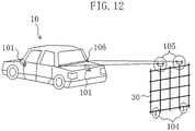
- Fig. 10 is a block diagram functionally showing the structure of the calibration system according to the present embodiment.
- the vehicle 10 includes, in addition to the cameras 101, a camera calibration means 108 for conducting calibration of the cameras 101, an image converting means 102 for applying a prescribed processing to the captured images of the cameras 101 for image conversion, and an image display means 103 such as a monitor for displaying the converted image.
- the vehicle 10 also includes the joint means 107b and target point 106 as described above.
- the target apparatus 30 includes the positional adjustment means 104, scope means 105 and joint means 107a as described above.
- the camera calibration means 108 which conducts camera calibration based on calibration data described below, is not an essential element to be provided within the vehicle 10, since a real-time processing is not always required.
- the camera calibration means 108 can be implemented with a general-purpose computer capable of operating a calibration software. When implemented with a general-purpose computer, the camera calibration means 108 may be placed at a remote location from the vehicle 10 so that the obtained calibration data may be transmitted to the computer by means of a storage medium such as floppy disk and memory card, or through communication such as radio or cable communication.
- Fig. 11 is a diagram showing the relation between a world coordinate system, a camera coordinate system and image coordinates based on a pinhole camera model. In calibration, the position and orientation of the camera in the world coordinate system are calculated using the feature point PP.
- f denotes the focal length of the camera
- Pv(u, v) denotes an image coordinate value of the feature point PP as captured with the camera
- Pe(Xe, Ye, Ze) denotes a coordinate value of the feature point PP in the camera coordinate system
- Pw(Xw, Yw, Zw) denotes a coordinate value of the feature point PP in the world coordinate system.
- a 3 ⁇ 3 rotation matrix for making the respective axes of the coordinate systems in parallel with each other is R(rll, ..., r33), and a translation vector for matching the respective origins is T(tx, ty, tz)
- camera calibration is nothing less than a process of obtaining each element of the rotation matrix R (corresponding to the orientation of the camera) and each element of the translation vector T (corresponding to the position of the camera).
- the number of unknown parameters for determining the orientation and position of the camera is six in total, i.e., three for the rotating matrix R (there are nine matrix elements, but independent parameters are only three rotation angles about the respective axes X, Y and Z because this is a rotation matrix), and three for the translation vector T.
- Two equations for u and v can be obtained by substituting a set of the image coordinate value Pv(u, v) and its corresponding coordinate value Pw(Xw, Yw, Zw) in the world coordinate system, i.e., a set of calibration data, for the above equation. Accordingly, the aforementioned six parameter values can be obtained with at least three sets of calibration data.
- the equation is generally solved by the least-square method or the like using the calibration data regarding as many feature points as possible that are dispersed in a wide range.
- a multiplicity of points each having a known exact coordinate value in a predetermined coordinate system i.e., feature points PP
- a multiplicity of points each having a known exact coordinate value in a predetermined coordinate system i.e., feature points PP
- the target apparatus 30 having the feature points PP must be accurately positioned with respect to the vehicle 10.
- the calibration data is manually created by the following two steps using the accurately positioned target apparatus 30:
- the target apparatus can be realized in a portable, compact form.
- the positional relation between the vehicle 10 and the target apparatus 30 is fixed to a prescribed relation by using the scope means without making the vehicle 10 and the target apparatus 30 in contact with each other.
- the joint means for physically fixing the vehicle 10 and the target apparatus 30 as in the first embodiment is not used in the second embodiment.
- Figs. 13A and 13B are diagrams showing positional adjustment of the target apparatus 30 according to the present embodiment.
- Figs. 13A and 13B show the states before and after positioning, respectively.
- the target points 106 for positioning are respectively set at the lower right and left corners of the rear window of the vehicle 10.
- the position of the target apparatus 30 is finely adjusted such that each target point 106 is located on the same line as that connecting the view point and the centers of two circular glasses 501 of the corresponding scope means 105.
- the structure of the scope means 105 is not limited to that described herein, and another structure may also be possible.
- a laser-beam emitting apparatus may be used as the scope means, and the position of the target apparatus 30 may be adjusted such that the emitted laser beam light is incident on the target point 106. This is advantageous in that the position can be confirmed without looking through a scope.
- a reflecting plate may be provided at the target point 106 in order to facilitate confirmation that the laser beam light is incident on the target point 106.
- the scope means may also be provided with a means for receiving the reflected light, so as to notify completion of the positional adjustment with a sound such as buzzer in response to reception of the reflected light at the light-receiving means.
- Fig. 14A, 14B and 14C it is assumed that positioning of the target apparatus is conducted using two scope means, and that the target apparatus 30 has a fixed height and is movable in the four directions (front, rear, right and left) on the plane where the vehicle 10 is located (i.e., the road surface S ).
- a line of sight VL1 through the scope means 105 is in parallel with the road surface S, and extends through the target point 106.
- Fig. 14B when the target points 106 at the upper right and left corners of the rear window of the vehicle 10 are viewed from each of the positions VP-1, VP-2, VP-3, each target point 106 exactly matches the centers of the two circular glasses 501 when viewed through the scope means 105. This makes it difficult to locate the target apparatus 30 at a correct position.
- a line of sight VL2 through the scope means 105 may be rendered at an angle with the plane on which the target apparatus 30 is moved, i.e., the road surface S, as shown in Fig. 14C .
- the positions of the scope means and the target points must be carefully determined in view of the possibility of the same disadvantage.
- Calibration data may be manually created in the case of using only a small number of feature points or calibrating only a small number of cameras.
- a large number of feature points are used or a large number of cameras must be calibrated, such a manual operation would be extremely time-consuming in terms of calibration.
- inputting the image coordinates of the feature points requires close attention. Therefore, long-time operation is hard for the operator, and also the tired operator may wrongly input the coordinates, which may result in degraded calibration accuracy.
- the calibration data is automatically created in the third embodiment of the present invention.
- Fig. 15 is a block diagram functionally showing the structure of a calibration system according to the third embodiment of the present invention.
- the vehicle 10 includes control means 109 for controlling the target apparatus 30, and storage means for storing control data 111 for automatically creating the calibration data.
- the target apparatus 30 includes feature-point generating means 110 for generating a feature point according to a control signal from the control means 109.
- the control means 109 transmits a control signal to the feature-point generating means 110 so as to cause the feature-point generating means 110 to generate a feature point required to adjust the camera 101, whereby the calibration data is automatically or semi-automatically created.
- the calibration data is automatically or semi-automatically created.
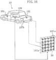
- Fig. 16 is a diagram showing the structure of a calibration system according to the present embodiment.
- the feature-point generating means 110 generates a feature point by using light-emitting means 110a.
- an internal driving means receives a control signal from the control means 109 and causes the light-emitting means 110a to generate a feature point for calibration accordingly.
- the camera 101 is a normal CCD (charge coupled device) camera or an infrared camera, an electronic flash, incandescent lamp or the like can be used as the light-emitting means 110a.
- CCD charge coupled device
- an electronic flash, incandescent lamp or the like can be used as the light-emitting means 110a.
- an inter-frame difference method is effective as a method for automatically detecting a light-emitting position.
- the difference between successive two frames is calculated in order to extract the position having the maximum difference.
- the process of extracting a feature point includes the following steps:
- the calibration data of the camera 101 i.e., the data having spatial coordinates of each feature point mapped with a coordinate value on the captured image can be automatically produced.
- efficiency of the camera calibration can be significantly improved.
- control means 109 retains in advance the data having the number of each feature point of the target apparatus 30 mapped with spatial coordinates thereof as the control data 111.
- Table 1 below is an example of the control data 111.
- the control means 109 sequentially obtains the feature point numbers from the control data 111 as shown in Table 1, and transmits a control signal to the target apparatus 30 so as to cause light emission of the feature point corresponding to the feature point number. Then, by conducting Steps ST1 to ST5, coordinates of the feature point on the captured image of the camera 101 are obtained. This coordinate value is mapped with a spatial coordinate value of the feature point in the control data 111, whereby a pair of calibration data is obtained.
- Spatial Coordinate Value of Feature Point 1 1 (X11, Y11, Z11) 1 2 (X12, Y12, Z12) ⁇ ⁇ ⁇ 1 N (X1N, Y1N, Z1N) 2 1 (X21, Y21, Z21) 2 2 (X22, Y22, Z22) ⁇ ⁇ ⁇ 2 N (X2N, Y2N, Z2N) M 1 (XM1, YM1, ZM1) M 2 (XM2, YM2, ZM2) ⁇ ⁇ ⁇ M N (XMN, YMN, ZMN)
- the control means 109 first obtains an installation position of the target apparatus 30 according to a prescribed method, and takes from the control data 111 as shown in Table 2 only the data having an installation position number corresponding to the installation position. With this data, the control means 109 then sequentially obtains the feature point numbers and transmits a control signal to the target apparatus 30 so as to cause light emission of the feature point corresponding to the obtained feature point number. Thereafter, by conducting Steps ST1 to ST5, the coordinates of the feature point on the captured image of the camera 101 are obtained. This coordinate value is mapped with a special coordinate value of that feature point within the data, whereby a pair of calibration data is obtained.
- control data 111 need be measured only once initially. Even if any positional displacement of the camera 101 occurs for some reason, the same control data 111 can be used for re-calibration as long as the positional relation between the vehicle 10 and the target apparatus 30 has not been changed. However, if the joint means are deformed by any impact, or the scope means and/or target points are deformed, the spatial coordinate values of the feature points described in the control data 111 themselves may possibly be deviated. In such a case, it is desirable to re-measure the spatial coordinate values of the feature points.
- Whether or not any positional displacement of the camera 101 has occurred or not can be easily determined by installing the target apparatus 30 and monitoring the installed target apparatus 30 with the camera 101 to see if a feature point is located at a prescribed position on the image converted by the image converting means 102.
- a special line (including radio transmission) connecting the control means 109 and the feature-point generating means 110 may be provided, or a signal line may be incorporated into the joint means 107a, 107b.
- transmission of the power required for light emission of the feature points from the vehicle 10 to the target apparatus 30 through the joint means 107a, 107b would eliminate the need to independent power supply to the target apparatus 30. Thus, reduction in size and weight of the target apparatus 30 can be realized.
- the positional relation between the mobile object having cameras mounted thereon and the target apparatus for calibrating the cameras is fixed to a prescribed relation either physically (with contact) or without contact.
- the mobile object and the target apparatus are appropriately disposed, and then the positional relation therebetween is obtained, so that camera calibration is conducted using the positional relation thus obtained.
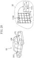
- Fig. 17 is a diagram showing the structure of a calibration system according to an embodiment being of illustrative purpose.
- the target apparatus 30 includes a target data obtaining means 114 formed from stereo cameras (cameras having the same focal length and disposed such that their respective optical axes become in parallel with each other and their respective image planes are located on the same plane), and a position calculating means 113 for calculating the positional relation of the target apparatus 30 itself with the vehicle 10 from the data obtained by the target data obtaining means 114.
- the position calculating means 113 and the target data obtaining means 114 form a positional-relation estimating means according to the present invention.
- the target data obtaining means 114 obtains a coordinate value in a coordinate system based on the target apparatus 30 (coordinate system 1), regarding each target point 106 having a known position in a coordinate system based on the vehicle 10 (coordinate system 2).
- the position calculating means 113 calculates the positional relation of the target apparatus 30 with the vehicle 10 from the coordinate values obtained by the target data obtaining means 114, and calculates a coordinate value of each feature point of the target apparatus 30 in the coordinate system 2 based on the calculated positional relation.
- Fig. 18 is a flowchart illustrating a flow of the process of calculating the coordinate value of the feature point in the coordinate system 2.
- individual cameras forming the stereo cameras are ideal pinhole cameras having no lens distortion and the like.
- Step S1 the target apparatus 30 is installed.
- the target apparatus 30 is positioned such that the respective images of the stereo cameras forming the target data obtaining means 114 include the target points 106. This is because the positional relation between the vehicle 10 and the target apparatus 30 is calculated under the condition that all of the target points 106 required for calculation are included in the stereo camera images.
- the ultimate goal is to calibrate the cameras 101 mounted on the vehicle 10
- the coordinate system 1 based on the target apparatus 30 is set appropriately.
- the coordinate system 1 is used to calculate the coordinate values of the target points 106. Therefore, the coordinate system 1 may be set based on any point of the target apparatus 30. Note that a camera parameter of the stereo cameras in the coordinate system 1 must be calculated in advance.
- Step S2 the coordinate values of the target points 106 in the coordinate system 1 are measured.
- all of the target points 106 required for calculation are captured with the stereo cameras forming the target data obtaining means 114, whereby the respective coordinate values of the target points 106 in the coordinate system 1 are calculated.
- the respective coordinate values of the target point 106 in the right and left camera images, (Xr, Yr) and (Xl, Yl), may either be manually obtained by, e.g., clicking with a mouse or automatically.
- Step S3 the positional relation between the coordinate system 1 and the coordinate system 2 based on the vehicle 10 is calculated.
- x 2 y 2 z 2 r 1 r 2 r 3 r 4 r 5 r 6 r 7 r 8 r 9 x 1 y 1 z 1 + t x t y t z
- Equation (2) ri is an element of a 3 ⁇ 3 matrix representing rotation for making the coordinate axes of the coordinate system 1 in parallel with the respective coordinate axes of the coordinate system 2; and tx, ty, tz are elements of a translation vector for moving the origin of the coordinate system 1 to the origin of the coordinate system 2.
- the coordinates (X1, X1, Z1) in the coordinate system 1 can be transformed into the coordinates (X2, Y2, Z2) in the coordinate system 2.
- These unknown parameters can be obtained by substituting a set of the respective coordinates of the target point 106 in the coordinate systems 1 and 2 for Equation (2) and solving the resultant simultaneous equations.
- Equation (2) seems to have twelve unknown parameters. However, since ri is formed from rotation parameters about X, Y and Z axes of the coordinate system 1, the number of original variables is three. Accordingly, the total number of unknown parameters is six. Thus, the unknown parameters can be obtained with at least two sets of target values 106 (because three equations are obtained from a single set). Note that, in practice, in order to reduce calculation error, many target points are generally used to obtain the equations, so that the unknown parameters best satisfying the equations are obtained by, e.g., the least-square method.
- Step S4 coordinate values of the feature points of the target apparatus 30 in the coordinate system 2 are calculated. More specifically, since the parameters representing the positional relation between the coordinate systems 1 and 2 are obtained in Step S3, the coordinate value of each feature point in the coordinate system 1 can be transformed into a coordinate value in the coordinate system 2. This transformation is conducted by merely inputting the pre-measured coordinate value of the feature point in the coordinate system 1 as (X1, Y1, Z1) of Equation (2).
- the stereo cameras are used to measure the coordinate values in the coordinate system 1 of the target points 106 on the vehicle 10.
- other methods may alternatively be used.
- distance measurement radar may be used as a target data obtaining means 114A.
- a radar reflecting plate is provided at the target points 106.
- the effects of the present invention allow the camera calibration to be developed as service businesses at places other than those with a large site like factories.
- camera calibration can be provided as a part of services at a car-maintenance service center. Accordingly, businesses receiving compensation for services from the customers can be realized. Since it is expected that the vehicle surrounding monitoring systems be widely used in the future and there be exchange or addition of the camera and a possibility of frequent positional displacement of the camera due to a traffic accident or vehicle running, it is naturally expected that such the service business is widely disseminated.
- the target apparatus 30 stored at the service center is installed near the vehicle 10 having the cameras 101 to be calibrated mounted thereon.
- the installation position of the target apparatus 30 is determined such that the target data obtaining means 114 of the target apparatus 30 can catch the target points 106 on the vehicle 10 and that the cameras 101 catch the feature points on the target apparatus 30 as many as possible.
- the target points 106 are caught by the target data obtaining means 114.
- images including the target points 106 are captured with both the right and left cameras.
- the positional relation between the vehicle 10 and the target apparatus 30 is obtained by the position calculating means 113, and the coordinate values of the feature points as viewed from the vehicle 10 are calculated. This calculation result is then transmitted to the camera calibration means 108 of the vehicle 10.
- This transmission may be conducted by any method.
- the transmission may be conducted over a cable or radio network, or by means of a storage medium such as floppy disk and memory card.
- the camera calibration means 108 calibrates each camera 101 based on both the image coordinates of the feature points captured with the cameras 101 and the coordinate data of the feature points received from the target apparatus 30.
- the series of Steps SS1 to SS4 is conducted repeatedly.
- the target apparatus 30 is placed to face each side of the vehicle, so that the series of Steps SS1 to SS4 is conducted once for each side.
- the target points 106 must be provided not only on the rear side of the vehicle, but also on the front, right and left sides thereof.
- the image converting means 102 and the display means 103 are provided inside the vehicle 10. However, these means may alternatively be provided at other positions.
- the present invention is also applicable in the case where the cameras are mounted on the mobile objects other than the vehicles, such as trains, airplanes or robots.
- the camera 101 monitoring the road surface rearward is mounted on the vehicle 10 as shown in Fig. 22A .
- the camera 101 is mounted at a height h of 1,000 mm above the ground, and orientation ⁇ of 60° from the vertical axis.
- the point on the road surface corresponding to the optical axis is shifted by the distance d2 of about 14 cm.
- the positional relation between the mobile object and the target apparatus is either fixed to a prescribed relation by the positioning means or obtained by the positional-relation estimating means. Therefore, the mobile object need no longer be positioned with high precision for camera calibration. Accordingly, calibration of the cameras mounted on the mobile object is simplified.
Landscapes
- Engineering & Computer Science (AREA)
- Computer Vision & Pattern Recognition (AREA)
- Physics & Mathematics (AREA)
- General Physics & Mathematics (AREA)
- Theoretical Computer Science (AREA)
- Multimedia (AREA)
- Mechanical Engineering (AREA)
- Length Measuring Devices By Optical Means (AREA)
- Studio Devices (AREA)
- Length Measuring Devices With Unspecified Measuring Means (AREA)
Claims (4)
- Kalibrierungssystem, umfassend:ein mobiles Objekt (2), an dem eine Kamera (1, 101) montiert ist; undeine Zielvorrichtung (3, 30) zum Kalibrieren der Kamera (1);
gekennzeichnet durchein Positionierungsmittel (107a, 107b), das an mindestens einem aus dem mobilen Objekt (2) und der Zielvorrichtung (3, 30) zum Festlegen einer Positionsbeziehung zwischen dem mobilen Objekt (2) und der Zielvorrichtung (3, 30) auf eine vorgeschriebene Beziehung vorgesehen ist, wobei das Positionierungsmittel (107a, 107b) mindestens eines aus i) einem Verbindungsmittel aufweist, um die Zielvorrichtung (3, 30) physisch an dem mobilen Objekt (2) zu fixieren und ii) einem Suchermittel (105), welches an mindestens einem aus dem mobilen Objekt (2) und der Zielvorrichtung (3, 30) vorgesehen ist, um die Zielvorrichtung (3, 30) bezüglich eines Zielpunktes zu positionieren, der sich an dem anderen befindet. - Kalibrierungssystem nach Anspruch 1, wobei die Zielvorrichtung (3, 30) einen Funktionspunkt (PP) aufweist, der dazu in der Lage ist, Licht unter einer externen Steuerung zu emittieren, und wobei das mobile Objekt (2) ein Steuermittel zum Steuern der Lichtemission des Funktionspunktes der Zielvorrichtung (3, 30) beinhaltet.
- Zielvorrichtung (3, 30) zum Kalibrieren einer Kamera (1, 101), die an einem mobilen Objekt (2) montiert ist, gekennzeichnet durch:ein Positionierungsmittel (107a, 107b) zum Festlegen einer Positionsbeziehung zwischen dem mobilen Objekt (2) und der Zielvorrichtung (3, 30) auf eine vorgeschriebene Beziehung, wobei das Positionierungsmittel (107a, 107b) mindestens eines aus i) einem Verbindungsmittel aufweist, um die Zielvorrichtung (3, 30) physisch an dem mobilen Objekt (2) zu fixieren und ii) einem Suchermittel (105), welches an mindestens einem aus dem mobilen Objekt (2) und der Zielvorrichtung (3, 30) vorgesehen ist, um die Zielvorrichtung (3, 30) bezüglich eines Zielpunktes zu positionieren, der sich an dem anderen befindet.
- Verfahren zum Kalibrieren einer Kamera (1, 101), die an einem mobilen Objekt (2) montiert ist, umfassend folgende Schritte:Vorbereiten einer Zielvorrichtung (3, 30) für die Kalibrierung um das mobile Objekt (2) herum;
gekennzeichnet durchFestlegen einer Position der Zielvorrichtung (3, 30), so dass die Zielvorrichtung (3, 30) eine vorgeschriebene Positionsbeziehung zu dem mobilen Objekt (2) aufweist, durch Verwenden eines Positionierungsmittels (107a, 107b), das an mindestens einem aus dem mobilen Objekt (2) und der Zielvorrichtung (3, 30) vorgesehen ist; wobei der Schritt zum Festlegen mindestens eines aus i) physischem Fixieren der Zielvorrichtung (3, 30) an dem mobilen Objekt (2) oder ii) Verwenden eines Suchermittels(105) beinhaltet, das an mindestens einem aus dem mobilen Objekt (2) und der Zielvorrichtung (3, 30) bereitgestellt ist, um die Zielvorrichtung (3, 30) bezüglich eines Zielpunktes zu positionieren, der sich an dem anderen befindet; undErfassen eines Funktionspunktes der Zielvorrichtung (3, 30) mit der Kamera (1, 101), wobei die Kamera (1, 101) basierend auf einer Beziehung zwischen den Bildkoordinaten des Funktionspunktes und dessen echten Koordinaten kalibriert wird.
Applications Claiming Priority (2)
| Application Number | Priority Date | Filing Date | Title |
|---|---|---|---|
| JP2000018409 | 2000-01-27 | ||
| JP2000018409 | 2000-01-27 |
Publications (3)
| Publication Number | Publication Date |
|---|---|
| EP1120746A2 EP1120746A2 (de) | 2001-08-01 |
| EP1120746A3 EP1120746A3 (de) | 2006-05-17 |
| EP1120746B1 true EP1120746B1 (de) | 2017-05-24 |
Family
ID=18545264
Family Applications (1)
| Application Number | Title | Priority Date | Filing Date |
|---|---|---|---|
| EP01101811.6A Expired - Lifetime EP1120746B1 (de) | 2000-01-27 | 2001-01-26 | Kalibrierungssystem, Zielgerät und Kalibrierungsverfahren |
Country Status (3)
| Country | Link |
|---|---|
| US (1) | US6542840B2 (de) |
| EP (1) | EP1120746B1 (de) |
| KR (1) | KR20010078102A (de) |
Families Citing this family (75)
| Publication number | Priority date | Publication date | Assignee | Title |
|---|---|---|---|---|
| US20050146605A1 (en) * | 2000-10-24 | 2005-07-07 | Lipton Alan J. | Video surveillance system employing video primitives |
| US7868912B2 (en) * | 2000-10-24 | 2011-01-11 | Objectvideo, Inc. | Video surveillance system employing video primitives |
| US8564661B2 (en) * | 2000-10-24 | 2013-10-22 | Objectvideo, Inc. | Video analytic rule detection system and method |
| US20050162515A1 (en) * | 2000-10-24 | 2005-07-28 | Objectvideo, Inc. | Video surveillance system |
| US8711217B2 (en) | 2000-10-24 | 2014-04-29 | Objectvideo, Inc. | Video surveillance system employing video primitives |
| US9892606B2 (en) * | 2001-11-15 | 2018-02-13 | Avigilon Fortress Corporation | Video surveillance system employing video primitives |
| WO2002099739A1 (en) * | 2001-06-05 | 2002-12-12 | Matrox Electronic Systems Ltd. | Model-based recognition of objects using a calibrated image system |
| DE10229334B4 (de) * | 2002-06-29 | 2010-09-23 | Robert Bosch Gmbh | Verfahren und Vorrichtung zur Kalibrierung von Sensoren im Kraftfahrzeug mittels eines Kalibrierobjekts mit Triple-Spiegel als Bezugsmerkmal |
| DE10246067B4 (de) * | 2002-10-02 | 2008-01-03 | Robert Bosch Gmbh | Verfahren und Vorrichtung zur Kalibrierung eines Bildsensorsystems in einem Kraftfahrzeug |
| DE10246066B4 (de) * | 2002-10-02 | 2007-11-22 | Robert Bosch Gmbh | Verfahren und Vorrichtung zur Kalibrierung eines Bildsensorsystems in einem Kraftfahrzeug |
| CN101140894A (zh) * | 2003-03-26 | 2008-03-12 | 阿森姆布里昂股份有限公司 | 用于校准装置的方法、用于校准多个并排放置的装置的方法以及适于实施这种方法的物体 |
| US7529424B2 (en) * | 2003-05-02 | 2009-05-05 | Grandeye, Ltd. | Correction of optical distortion by image processing |
| CN1323547C (zh) * | 2003-10-22 | 2007-06-27 | 西安交通大学 | 一种车载摄像机外部参数三线标定方法 |
| US8427538B2 (en) | 2004-04-30 | 2013-04-23 | Oncam Grandeye | Multiple view and multiple object processing in wide-angle video camera |
| DE102004033468A1 (de) * | 2004-06-05 | 2005-12-22 | Adc Automotive Distance Control Systems Gmbh | Verfahren zur Kalibrierung einer Kamera |
| DE102004048400A1 (de) | 2004-10-01 | 2006-04-06 | Robert Bosch Gmbh | Verfahren für die Erfassung einer optischen Struktur |
| DE102004056669A1 (de) * | 2004-10-13 | 2006-04-20 | Robert Bosch Gmbh | Einrichtung für die Kalibrierung eines Bildsensorsystems in einem Kraftfahrzeug |
| US7720580B2 (en) | 2004-12-23 | 2010-05-18 | Donnelly Corporation | Object detection system for vehicle |
| DE102005009198A1 (de) * | 2005-02-25 | 2006-08-31 | Adc Automotive Distance Control Systems Gmbh | Sensor für ein Kraftfahrzeug |
| US7782374B2 (en) * | 2005-03-03 | 2010-08-24 | Nissan Motor Co., Ltd. | Processor and processing method for generating a panoramic image for a vehicle |
| JP4727329B2 (ja) * | 2005-07-15 | 2011-07-20 | パナソニック株式会社 | 画像合成装置及び画像合成方法 |
| DE102006056232B4 (de) * | 2006-11-29 | 2017-08-17 | Bayerische Motoren Werke Aktiengesellschaft | Vorrichtung zur Kalibrierung einer Kamera |
| DE102008010805A1 (de) * | 2008-02-23 | 2009-08-27 | Adc Automotive Distance Control Systems Gmbh | Vorrichtung und Verfahren zum Anordnen einer Kalibriertafel vor einem Fahrzeug-Kamerasystem |
| JPWO2009119229A1 (ja) * | 2008-03-26 | 2011-07-21 | コニカミノルタホールディングス株式会社 | 3次元撮像装置及び3次元撮像装置の校正方法 |
| CN102027744A (zh) * | 2008-05-19 | 2011-04-20 | 松下电器产业株式会社 | 车辆周围监视装置和车辆周围监视方法 |
| US8113394B2 (en) * | 2008-05-29 | 2012-02-14 | The Build-Up Plastic & Metal Co., Ltd. | Garment hanger including fold-over paper sizer |
| JP4555876B2 (ja) * | 2008-05-30 | 2010-10-06 | 株式会社日本自動車部品総合研究所 | 車載カメラのキャリブレーション方法 |
| US9279882B2 (en) * | 2008-09-19 | 2016-03-08 | Caterpillar Inc. | Machine sensor calibration system |
| US8918302B2 (en) * | 2008-09-19 | 2014-12-23 | Caterpillar Inc. | Machine sensor calibration system |
| TWI336670B (en) * | 2008-12-03 | 2011-02-01 | Ind Tech Res Inst | Method for determining the angular magnitude of imaging acquiring apparatus and vehicle collision warning system using thereof |
| KR101023275B1 (ko) * | 2009-04-06 | 2011-03-18 | 삼성전기주식회사 | 차량용 카메라 시스템의 캘리브레이션 방법 및 장치, 차량용 카메라 시스템의 각도상 오정렬을 판단하는 방법 및 이를 수행하는 전자 제어 유닛 |
| DE112009004830T5 (de) * | 2009-05-29 | 2012-06-14 | Toyota Jidosha Kabushiki Kaisha | Spektrummessvorrichtung für Bewegungsobjekt |
| DE102009028606B4 (de) | 2009-08-18 | 2018-10-04 | Robert Bosch Gmbh | Verfahren zum Kalibrieren einer Fahrerassistenzsystem-Kamera eines Kraftfahrzeugs sowie Kalibriereinrichtung für eine solche Fahrerassistenzsystem-Kamera |
| US20110102583A1 (en) * | 2009-10-30 | 2011-05-05 | Kim Kinzalow | Rear view camera system and calibration method |
| JP5299231B2 (ja) * | 2009-11-17 | 2013-09-25 | 富士通株式会社 | キャリブレーション装置 |
| EP2577227A1 (de) * | 2010-06-01 | 2013-04-10 | Valeo Schalter und Sensoren GmbH | Verfahren zur bestimmung einer anordnung einer tragbaren kommunikationsvorrichtung innerhalb eines koordinatensystems eines fahrzeuges, zugehörige datenverarbeitungseinheit und tragbare kommunikationsvorrichtung |
| WO2012001793A1 (ja) * | 2010-06-30 | 2012-01-05 | 富士通株式会社 | 画像処理プログラムおよび画像処理装置 |
| DE102010062297B4 (de) | 2010-12-01 | 2023-11-23 | Bayerische Motoren Werke Aktiengesellschaft | Verfahren zur Kalibrierung einer Videokamera in oder an einem Fahrzeug |
| US20130173109A1 (en) * | 2011-12-28 | 2013-07-04 | Ramadev Burigsay Hukkeri | Vehicle model calibration system for a mobile machine |
| US9870704B2 (en) * | 2012-06-20 | 2018-01-16 | Conduent Business Services, Llc | Camera calibration application |
| JP6009894B2 (ja) | 2012-10-02 | 2016-10-19 | 株式会社デンソー | キャリブレーション方法、及びキャリブレーション装置 |
| DE102012218123B4 (de) * | 2012-10-04 | 2014-09-18 | Robert Bosch Gmbh | Verfahren und Vorrichtung zum Kalibrieren zumindest eines optischen Sensors eines Fahrzeugs |
| KR102001659B1 (ko) * | 2012-11-19 | 2019-07-19 | 한국전자통신연구원 | 차량용 카메라 캘리브레이션 장치 및 방법 |
| SE538340C2 (sv) * | 2013-02-28 | 2016-05-24 | Scania Cv Ab | Mätsystem |
| DE102013212843A1 (de) * | 2013-07-02 | 2015-01-08 | Continental Automotive Gmbh | Kameraanordnung, Verfahren und Vorrichtung zum Betreiben einer Kameraanordnung |
| US9386302B2 (en) * | 2014-05-21 | 2016-07-05 | GM Global Technology Operations LLC | Automatic calibration of extrinsic and intrinsic camera parameters for surround-view camera system |
| US10931933B2 (en) * | 2014-12-30 | 2021-02-23 | Eys3D Microelectronics, Co. | Calibration guidance system and operation method of a calibration guidance system |
| US10013761B2 (en) * | 2015-03-24 | 2018-07-03 | Intel Corporation | Automatic orientation estimation of camera system relative to vehicle |
| US11228700B2 (en) | 2015-10-07 | 2022-01-18 | Magna Electronics Inc. | Vehicle vision system camera with adaptive field of view |
| CN105253063B (zh) * | 2015-10-21 | 2018-07-06 | 奇瑞汽车股份有限公司 | 一种泊车影像静态车辅线标定装置和标定方法 |
| US10300859B2 (en) | 2016-06-10 | 2019-05-28 | Magna Electronics Inc. | Multi-sensor interior mirror device with image adjustment |
| JP6962372B2 (ja) * | 2017-08-25 | 2021-11-05 | 株式会社ソシオネクスト | 補正装置、補正プログラム及び記録媒体 |
| US11009586B2 (en) | 2017-08-31 | 2021-05-18 | Bosch Automotive Service Solutions Inc. | Mobile calibration apparatus for vehicle sensors |
| DE112018005928T5 (de) | 2017-12-20 | 2020-07-30 | Robert Bosch Gesellschaft mit beschränkter Haftung | Tragbare vorrichtung für fahrzeugsensorkalibrierung |
| FR3075354B1 (fr) * | 2017-12-20 | 2020-12-25 | Thales Sa | Procede de reperage d'un plan, dispositifs et procedes associes |
| US10852731B1 (en) * | 2017-12-28 | 2020-12-01 | Waymo Llc | Method and system for calibrating a plurality of detection systems in a vehicle |
| WO2019138646A1 (ja) | 2018-01-10 | 2019-07-18 | ソニー株式会社 | キャリブレーション装置とキャリブレーション方法およびキャリブレーションチャート装置 |
| WO2019162732A1 (en) * | 2018-02-26 | 2019-08-29 | National Research Council Of Canada | Kit and method for calibrating large volume 3d imaging systems |
| US10942045B1 (en) * | 2018-04-03 | 2021-03-09 | Waymo Llc | Portable sensor calibration target for autonomous vehicle |
| US11781860B2 (en) | 2018-04-30 | 2023-10-10 | BPG Sales and Technology Investments, LLC | Mobile vehicular alignment for sensor calibration |
| US11835646B2 (en) | 2018-04-30 | 2023-12-05 | BPG Sales and Technology Investments, LLC | Target alignment for vehicle sensor calibration |
| HRP20240567T1 (hr) | 2018-04-30 | 2024-07-05 | BPG Sales and Technology Investments, LLC | Usklađivanje vozila radi kalibracije senzora |
| US11243074B2 (en) | 2018-04-30 | 2022-02-08 | BPG Sales and Technology Investments, LLC | Vehicle alignment and sensor calibration system |
| US11597091B2 (en) | 2018-04-30 | 2023-03-07 | BPG Sales and Technology Investments, LLC | Robotic target alignment for vehicle sensor calibration |
| JP7057262B2 (ja) * | 2018-09-25 | 2022-04-19 | 本田技研工業株式会社 | 車両検査装置 |
| US11681030B2 (en) | 2019-03-05 | 2023-06-20 | Waymo Llc | Range calibration of light detectors |
| US11145087B2 (en) | 2019-04-04 | 2021-10-12 | Airpro Diagnostics, Llc | Optimized forward-facing camera calibration system with portable mounting apparatus and adaptable electronic calibration target display |
| US11112490B2 (en) | 2019-04-15 | 2021-09-07 | Argo AI, LLC | Apparatus for joint calibration of radar and camera systems for autonomous vehicle applications |
| CN109932706B (zh) * | 2019-04-19 | 2022-11-29 | 青岛中科慧畅信息科技有限公司 | 一种无人装卸物流装备系统激光雷达标定系统及标定方法 |
| US11629835B2 (en) * | 2019-07-31 | 2023-04-18 | Toyota Jidosha Kabushiki Kaisha | Auto-calibration of vehicle sensors |
| US11747453B1 (en) | 2019-11-04 | 2023-09-05 | Waymo Llc | Calibration system for light detection and ranging (lidar) devices |
| JP7323057B2 (ja) * | 2020-03-31 | 2023-08-08 | 日本電気株式会社 | 制御装置、制御方法、および、制御プログラム |
| US11279327B1 (en) | 2020-09-04 | 2022-03-22 | Richard L. Jackson, JR. | Vehicle sensor calibration target alignment system |
| DE102020131778A1 (de) * | 2020-12-01 | 2022-06-02 | Zf Cv Systems Global Gmbh | Verfahren zum Kalibrieren einer rückschauenden Kamera und Fahrzeug |
| CN115457148A (zh) * | 2022-09-16 | 2022-12-09 | 博众精工科技股份有限公司 | 一种旋转中心的标定方法、装置、计算机设备和存储介质 |
Family Cites Families (19)
| Publication number | Priority date | Publication date | Assignee | Title |
|---|---|---|---|---|
| US3770149A (en) * | 1971-11-26 | 1973-11-06 | J Aquila | Apparatus for towing wide vehicles |
| JPS63301690A (ja) | 1987-05-30 | 1988-12-08 | Toshiba Corp | Itvカメラ点検装置 |
| JPS63304791A (ja) | 1987-06-05 | 1988-12-13 | Fujitsu Ltd | カメラキャリブレ−ションにおける直線パタ−ン対応方式 |
| JPH0790494B2 (ja) | 1987-08-22 | 1995-10-04 | ファナック株式会社 | 視覚センサのキャリブレ−ション方法 |
| JPH0392712A (ja) | 1989-09-05 | 1991-04-17 | Fanuc Ltd | 画像処理装置と測距センサによる物体の3次元位置認識方法 |
| JPH0399952A (ja) | 1989-09-12 | 1991-04-25 | Nissan Motor Co Ltd | 車両用周囲状況モニタ |
| JPH03106547A (ja) | 1989-09-19 | 1991-05-07 | Shin Nippon Denki Sangyo Kk | ダイカスト用誘導溶解保持装置 |
| JP3106547B2 (ja) | 1991-05-28 | 2000-11-06 | 神鋼電機株式会社 | 視覚装置の幾何学的撮像特性較正方法 |
| FR2706345B1 (fr) | 1993-06-11 | 1995-09-22 | Bertin & Cie | Procédé et dispositif de repérage dans l'espace d'un objet mobile tel qu'un capteur ou un outil porté par un robot. |
| JPH0727408A (ja) | 1993-07-09 | 1995-01-27 | Fujitsu General Ltd | 空気調和機 |
| JP2970339B2 (ja) | 1993-09-27 | 1999-11-02 | 日本鋼管株式会社 | 耐転動疲労損傷性に優れたレール |
| JPH08285534A (ja) | 1995-04-12 | 1996-11-01 | Suzuki Motor Corp | 車載用画像処理装置 |
| US5960125A (en) * | 1996-11-21 | 1999-09-28 | Cognex Corporation | Nonfeedback-based machine vision method for determining a calibration relationship between a camera and a moveable object |
| JP3436074B2 (ja) | 1997-06-10 | 2003-08-11 | トヨタ自動車株式会社 | 車載ステレオカメラ |
| JPH1133962A (ja) | 1997-07-18 | 1999-02-09 | Yaskawa Electric Corp | ロボットの三次元位置センサのキャリブレーション 方法とその装置 |
| FR2770317B1 (fr) | 1997-10-24 | 2000-12-08 | Commissariat Energie Atomique | Procede d'etalonnage de la position et de l'orientation d'origine d'une ou plusieurs cameras mobiles et son application a la mesure de position tridimentionnelle d'objets fixes |
| JPH11134480A (ja) | 1997-10-28 | 1999-05-21 | Nissan Motor Co Ltd | 車載カメラ位置ずれ検出装置 |
| JP3516856B2 (ja) * | 1998-01-30 | 2004-04-05 | 富士重工業株式会社 | 車外監視装置 |
| JP3286306B2 (ja) | 1998-07-31 | 2002-05-27 | 松下電器産業株式会社 | 画像生成装置、画像生成方法 |
-
2001
- 2001-01-25 US US09/770,038 patent/US6542840B2/en not_active Expired - Lifetime
- 2001-01-26 EP EP01101811.6A patent/EP1120746B1/de not_active Expired - Lifetime
- 2001-01-27 KR KR1020010003871A patent/KR20010078102A/ko not_active Application Discontinuation
Also Published As
| Publication number | Publication date |
|---|---|
| EP1120746A3 (de) | 2006-05-17 |
| EP1120746A2 (de) | 2001-08-01 |
| US20010012985A1 (en) | 2001-08-09 |
| KR20010078102A (ko) | 2001-08-20 |
| US6542840B2 (en) | 2003-04-01 |
Similar Documents
| Publication | Publication Date | Title |
|---|---|---|
| EP1120746B1 (de) | Kalibrierungssystem, Zielgerät und Kalibrierungsverfahren | |
| JP3387911B2 (ja) | キャリブレーションシステムおよびキャリブレーション方法 | |
| CN110390695B (zh) | 一种基于ros的激光雷达、摄像头的融合标定系统及标定方法 | |
| CN110969663B (zh) | 一种相机外部参数的静态标定方法 | |
| US7342669B2 (en) | Three-dimensional shape measuring method and its device | |
| EP1266188B1 (de) | Vorrichtung und verfahren zum kalibrieren der relativlage zweier messeinrichtungen eines messsystems | |
| JP4167954B2 (ja) | ロボット及びロボット移動方法 | |
| US10643342B2 (en) | Group optimization depth information method and system for constructing a 3D feature map | |
| CN108227929B (zh) | 基于bim技术的增强现实放样系统及实现方法 | |
| Kang et al. | Accurate fruit localisation using high resolution LiDAR-camera fusion and instance segmentation | |
| CN111739101B (zh) | 一种消除车辆a柱盲区的装置和方法 | |
| CN106949845A (zh) | 基于双目立体视觉的二维激光振镜扫描系统及标定方法 | |
| CN108444390A (zh) | 一种无人驾驶汽车障碍物识别方法及装置 | |
| US20100201810A1 (en) | Image display apparatus and image display method | |
| CN101487895B (zh) | 显示鸟瞰车辆图像的倒车雷达系统 | |
| Xu et al. | An omnidirectional 3D sensor with line laser scanning | |
| TWI688502B (zh) | 用於警告車輛障礙物的設備 | |
| Zalud et al. | Fusion of thermal imaging and CCD camera-based data for stereovision visual telepresence | |
| CN104976968A (zh) | 一种基于led标签跟踪的三维几何测量方法及系统 | |
| CN110750153A (zh) | 一种无人驾驶车辆的动态虚拟化装置 | |
| CN105496556A (zh) | 一种用于手术导航的高精度光学定位系统 | |
| Schönbein et al. | Environmental Perception for Intelligent Vehicles Using Catadioptric Stereo Vision Systems. | |
| CN105571491A (zh) | 基于双目视觉的汽车底盘数据测量系统及其方法 | |
| CN106840137B (zh) | 一种四点式掘进机自动定位定向方法 | |
| CN113465572A (zh) | 一种基于相机成像几何关系的单目测距方法及系统 |
Legal Events
| Date | Code | Title | Description |
|---|---|---|---|
| PUAI | Public reference made under article 153(3) epc to a published international application that has entered the european phase |
Free format text: ORIGINAL CODE: 0009012 |
|
| AK | Designated contracting states |
Kind code of ref document: A2 Designated state(s): AT BE CH CY DE DK ES FI FR GB GR IE IT LI LU MC NL PT SE TR |
|
| AX | Request for extension of the european patent |
Free format text: AL;LT;LV;MK;RO;SI |
|
| PUAL | Search report despatched |
Free format text: ORIGINAL CODE: 0009013 |
|
| AK | Designated contracting states |
Kind code of ref document: A3 Designated state(s): AT BE CH CY DE DK ES FI FR GB GR IE IT LI LU MC NL PT SE TR |
|
| AX | Request for extension of the european patent |
Extension state: AL LT LV MK RO SI |
|
| 17P | Request for examination filed |
Effective date: 20060626 |
|
| AKX | Designation fees paid |
Designated state(s): DE FR GB IT SE |
|
| RAP1 | Party data changed (applicant data changed or rights of an application transferred) |
Owner name: PANASONIC CORPORATION |
|
| 17Q | First examination report despatched |
Effective date: 20111104 |
|
| RAP1 | Party data changed (applicant data changed or rights of an application transferred) |
Owner name: PANASONIC INTELLECTUAL PROPERTY MANAGEMENT CO., LT |
|
| GRAP | Despatch of communication of intention to grant a patent |
Free format text: ORIGINAL CODE: EPIDOSNIGR1 |
|
| STAA | Information on the status of an ep patent application or granted ep patent |
Free format text: STATUS: GRANT OF PATENT IS INTENDED |
|
| INTG | Intention to grant announced |
Effective date: 20170110 |
|
| GRAS | Grant fee paid |
Free format text: ORIGINAL CODE: EPIDOSNIGR3 |
|
| GRAA | (expected) grant |
Free format text: ORIGINAL CODE: 0009210 |
|
| STAA | Information on the status of an ep patent application or granted ep patent |
Free format text: STATUS: THE PATENT HAS BEEN GRANTED |
|
| AK | Designated contracting states |
Kind code of ref document: B1 Designated state(s): DE FR GB IT SE |
|
| REG | Reference to a national code |
Ref country code: GB Ref legal event code: FG4D |
|
| REG | Reference to a national code |
Ref country code: DE Ref legal event code: R096 Ref document number: 60150452 Country of ref document: DE |
|
| PG25 | Lapsed in a contracting state [announced via postgrant information from national office to epo] |
Ref country code: SE Free format text: LAPSE BECAUSE OF FAILURE TO SUBMIT A TRANSLATION OF THE DESCRIPTION OR TO PAY THE FEE WITHIN THE PRESCRIBED TIME-LIMIT Effective date: 20170524 |
|
| REG | Reference to a national code |
Ref country code: DE Ref legal event code: R097 Ref document number: 60150452 Country of ref document: DE |
|
| PG25 | Lapsed in a contracting state [announced via postgrant information from national office to epo] |
Ref country code: IT Free format text: LAPSE BECAUSE OF FAILURE TO SUBMIT A TRANSLATION OF THE DESCRIPTION OR TO PAY THE FEE WITHIN THE PRESCRIBED TIME-LIMIT Effective date: 20170524 |
|
| PLBE | No opposition filed within time limit |
Free format text: ORIGINAL CODE: 0009261 |
|
| STAA | Information on the status of an ep patent application or granted ep patent |
Free format text: STATUS: NO OPPOSITION FILED WITHIN TIME LIMIT |
|
| 26N | No opposition filed |
Effective date: 20180227 |
|
| GBPC | Gb: european patent ceased through non-payment of renewal fee |
Effective date: 20180126 |
|
| PG25 | Lapsed in a contracting state [announced via postgrant information from national office to epo] |
Ref country code: FR Free format text: LAPSE BECAUSE OF NON-PAYMENT OF DUE FEES Effective date: 20180131 |
|
| REG | Reference to a national code |
Ref country code: FR Ref legal event code: ST Effective date: 20180928 |
|
| PG25 | Lapsed in a contracting state [announced via postgrant information from national office to epo] |
Ref country code: GB Free format text: LAPSE BECAUSE OF NON-PAYMENT OF DUE FEES Effective date: 20180126 |
|
| PGFP | Annual fee paid to national office [announced via postgrant information from national office to epo] |
Ref country code: DE Payment date: 20200121 Year of fee payment: 20 |
|
| REG | Reference to a national code |
Ref country code: DE Ref legal event code: R071 Ref document number: 60150452 Country of ref document: DE |