US11009586B2 - Mobile calibration apparatus for vehicle sensors - Google Patents
Mobile calibration apparatus for vehicle sensors Download PDFInfo
- Publication number
- US11009586B2 US11009586B2 US16/113,096 US201816113096A US11009586B2 US 11009586 B2 US11009586 B2 US 11009586B2 US 201816113096 A US201816113096 A US 201816113096A US 11009586 B2 US11009586 B2 US 11009586B2
- Authority
- US
- United States
- Prior art keywords
- adjustable support
- vehicle
- segment
- adjustment mechanism
- operable
- Prior art date
- Legal status (The legal status is an assumption and is not a legal conclusion. Google has not performed a legal analysis and makes no representation as to the accuracy of the status listed.)
- Active, expires
Links
Images


Classifications
-
- G—PHYSICS
- G01—MEASURING; TESTING
- G01S—RADIO DIRECTION-FINDING; RADIO NAVIGATION; DETERMINING DISTANCE OR VELOCITY BY USE OF RADIO WAVES; LOCATING OR PRESENCE-DETECTING BY USE OF THE REFLECTION OR RERADIATION OF RADIO WAVES; ANALOGOUS ARRANGEMENTS USING OTHER WAVES
- G01S7/00—Details of systems according to groups G01S13/00, G01S15/00, G01S17/00
- G01S7/02—Details of systems according to groups G01S13/00, G01S15/00, G01S17/00 of systems according to group G01S13/00
- G01S7/40—Means for monitoring or calibrating
- G01S7/4004—Means for monitoring or calibrating of parts of a radar system
- G01S7/4026—Antenna boresight
- G01S7/4034—Antenna boresight in elevation, i.e. in the vertical plane
-
- G—PHYSICS
- G01—MEASURING; TESTING
- G01S—RADIO DIRECTION-FINDING; RADIO NAVIGATION; DETERMINING DISTANCE OR VELOCITY BY USE OF RADIO WAVES; LOCATING OR PRESENCE-DETECTING BY USE OF THE REFLECTION OR RERADIATION OF RADIO WAVES; ANALOGOUS ARRANGEMENTS USING OTHER WAVES
- G01S7/00—Details of systems according to groups G01S13/00, G01S15/00, G01S17/00
- G01S7/48—Details of systems according to groups G01S13/00, G01S15/00, G01S17/00 of systems according to group G01S17/00
- G01S7/497—Means for monitoring or calibrating
- G01S7/4972—Alignment of sensor
-
- G—PHYSICS
- G01—MEASURING; TESTING
- G01S—RADIO DIRECTION-FINDING; RADIO NAVIGATION; DETERMINING DISTANCE OR VELOCITY BY USE OF RADIO WAVES; LOCATING OR PRESENCE-DETECTING BY USE OF THE REFLECTION OR RERADIATION OF RADIO WAVES; ANALOGOUS ARRANGEMENTS USING OTHER WAVES
- G01S7/00—Details of systems according to groups G01S13/00, G01S15/00, G01S17/00
- G01S7/52—Details of systems according to groups G01S13/00, G01S15/00, G01S17/00 of systems according to group G01S15/00
- G01S7/52004—Means for monitoring or calibrating
-
- G—PHYSICS
- G01—MEASURING; TESTING
- G01S—RADIO DIRECTION-FINDING; RADIO NAVIGATION; DETERMINING DISTANCE OR VELOCITY BY USE OF RADIO WAVES; LOCATING OR PRESENCE-DETECTING BY USE OF THE REFLECTION OR RERADIATION OF RADIO WAVES; ANALOGOUS ARRANGEMENTS USING OTHER WAVES
- G01S17/00—Systems using the reflection or reradiation of electromagnetic waves other than radio waves, e.g. lidar systems
- G01S17/88—Lidar systems specially adapted for specific applications
-
- G01S2007/403—
-
- G01S2007/4034—
-
- G—PHYSICS
- G01—MEASURING; TESTING
- G01S—RADIO DIRECTION-FINDING; RADIO NAVIGATION; DETERMINING DISTANCE OR VELOCITY BY USE OF RADIO WAVES; LOCATING OR PRESENCE-DETECTING BY USE OF THE REFLECTION OR RERADIATION OF RADIO WAVES; ANALOGOUS ARRANGEMENTS USING OTHER WAVES
- G01S13/00—Systems using the reflection or reradiation of radio waves, e.g. radar systems; Analogous systems using reflection or reradiation of waves whose nature or wavelength is irrelevant or unspecified
- G01S13/88—Radar or analogous systems specially adapted for specific applications
- G01S13/93—Radar or analogous systems specially adapted for specific applications for anti-collision purposes
- G01S13/931—Radar or analogous systems specially adapted for specific applications for anti-collision purposes of land vehicles
- G01S2013/9327—Sensor installation details
- G01S2013/93271—Sensor installation details in the front of the vehicles
-
- G—PHYSICS
- G01—MEASURING; TESTING
- G01S—RADIO DIRECTION-FINDING; RADIO NAVIGATION; DETERMINING DISTANCE OR VELOCITY BY USE OF RADIO WAVES; LOCATING OR PRESENCE-DETECTING BY USE OF THE REFLECTION OR RERADIATION OF RADIO WAVES; ANALOGOUS ARRANGEMENTS USING OTHER WAVES
- G01S7/00—Details of systems according to groups G01S13/00, G01S15/00, G01S17/00
- G01S7/02—Details of systems according to groups G01S13/00, G01S15/00, G01S17/00 of systems according to group G01S13/00
- G01S7/40—Means for monitoring or calibrating
- G01S7/4004—Means for monitoring or calibrating of parts of a radar system
- G01S7/4026—Antenna boresight
- G01S7/403—Antenna boresight in azimuth, i.e. in the horizontal plane
Definitions
- This disclosure relates to the calibration of sensors, and in particular sensors using radar, optical, or sonic signals disposed within a vehicle for use with an Advanced Driver Assistance System.
- the associated sensors require calibration to achieve proper operation. Calibration may be required as part of regular maintenance, or on particular occasions such as the repair or replacement of the windshield or other glass components of the vehicle. Certain vehicular glass repairs may be completed on-site, such as at the vehicle owner's home or place of business.
- Current calibration tools are typically bulky and stationary, and require the vehicle to be brought into an automotive service center or similar controlled environment. It is therefore desirable to have a calibration apparatus that is sufficiently mobile that the calibration procedure may be performed at a desired location outside of an automotive service center. It is additionally desirable to make use of such a calibration apparatus to preserve a maximum amount of space in small facilities, and to optimize the existing space of a facility.
- One aspect of this disclosure is directed to a portable calibration apparatus that is advantageously foldable or compactable for storage or transport.
- the mobility of the portable calibration apparatus may be increased further by mounting it to a mobile support, such as a work vehicle.
- the mounting of the portable calibration device may be accomplished using a three-point hitch.
- the three-point hitch may comprise components to adjust the configuration of the portable calibration apparatus while mounted to the mobile support.
- Another aspect of this disclosure is directed to the utilization of a number of electric motors configured to improve the accuracy and repeatability of the placement and alignment of a portable calibration apparatus.
- a further aspect of this disclosure is directed to the control of the adjustment process of a portable calibration apparatus using an interface of a controller configured to operate electric motors configured to operate the placement and alignment of the portable calibration apparatus.
- the adjustment of the portable calibration apparatus is accomplished using a telescoping mechanism.
- the telescoping mechanism comprises a threaded cavity and threaded screw mechanism.
- a further aspect of this disclosure is directed to a mobile system for vehicle sensor calibration, the mobile system comprising a number of platforms operable to provide a level surface for a subject vehicle, a mobile support structure, a folding reference structure configured to be mounted onto the mobile support structure, and a support vehicle.
- the support vehicle comprises the mobile support structure.
- the folding reference structure is configured to be folded using a number of motors. In some such embodiments, the motors may be controlled via a user interface.
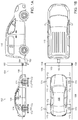
- FIG. 1 a is a side-view illustration of an embodiment of a mobile calibration apparatus during a calibration setup.
- FIG. 1 b is a top-view illustration of the embodiment of FIG. 1 a.
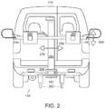
- FIG. 2 is a mid-view of the mobile calibration apparatus from the perspective of a vehicle's forward-facing sensor during the setup of calibration depicted in FIG. 1 .
- FIG. 3 is a diagrammatic illustration of a primary member of a mobile calibration apparatus.
- FIG. 4 is a diagrammatic illustration of a vertical-extension support of a primary member of a mobile calibration apparatus.
- FIG. 5 is a diagrammatic illustration of a horizontal-extension support of a primary member of a mobile calibration apparatus.
- FIG. 6 is an interior view of a console of a vehicle having controls for controlling a mobile calibration apparatus.
- FIG. 7 is a hitching mechanism operable to mount a primary member of a mobile calibration apparatus to a service vehicle of a mobile system.
- FIGS. 1 a and 1 b depict an embodiment of a mobile calibration system 102 for sensors of a subject vehicle 100 .
- the sensors (not shown) of the subject vehicle 100 are forward-facing, but other configurations may be embodied without deviating from the invention herein.
- the sensors of vehicle 100 are radar sensors, but other alternative embodiments may include camera sensors, LIDAR sensors, optical sensors, sonic sensors, or any other directional sensors known to one of ordinary skill in the art.
- the system 102 comprises a mobile calibration apparatus 104 integrated with a service vehicle 110 , which additionally provides support elements with respect to components of the mobile calibration apparatus.
- the mobile calibration apparatus 104 comprises a primary member 150 which is shown mounted to service vehicle 110 using hitch mechanism 152 .
- hitch mechanism 152 is operable to support mounting of the primary member 150 to the rear of service vehicle 110 , but other configurations are contemplated, such as mounting to the side of service vehicle 110 .
- Hitch mechanism 152 may be configured to support a permanent or detachable mounting of primary member 150 , and thus mounting to the front of service vehicle 110 is also achievable.
- service vehicle 110 may be advantageously operable to store primary member 150 such that the calibration system, is mobile using service vehicle 110 .
- measuring instruments 154 are coupled to the primary member 150 and utilized to position the service vehicle 110 at desired distance and angle to the sensors of subject vehicle 100 .
- a number means one or more.
- measuring instruments 154 are detachably coupled to primary member 150 , but in some embodiments measuring instruments 154 may be permanently coupled to primary member 150 .
- measuring instruments 154 comprise optical range-finders having digital leveling capabilities, but other configurations are contemplated such as measuring tapes, spirit levels, sonic range-finders, or any other alternative configuration known to one of ordinary skill in the art.
- the particular distance and angles for calibration of the sensors of subject vehicle 100 are determined by the particular specification of the sensors of subject vehicle 100 .
- Measuring instruments 154 are operable to support the position and angle of service vehicle 110 with respect to subject vehicle 100 using a number of measurement vectors 156 determined using measuring instruments 154 .
- measurement vectors 156 comprise optical vectors emitted by the measuring instruments 154 , but in any configuration measurement vectors 156 represent the proper distance and measurement angles of the service vehicle 110 with respect to the subject vehicle 100 .
- the mobile calibration system is intended to be operable in a field-service capacity, and thus is operable in environments that may be less ideal than automotive workshop conditions. If calibration is to be performed on uneven surfaces, the mobile calibration apparatus may additionally comprise a number of platform members 170 .
- Platform members 170 provide a level platform surface with height-adjustable foot structures to provide a sufficiently-level surface to operably perform calibration of the sensors of subject vehicle 100 .
- platform members 170 have sufficient strength to support the weight of subject vehicle 100 .
- the desired height and evenness of platform members 170 is achieved using height-adjustable foot structures 172 .
- height-adjustable foot structures 172 comprise screw-threaded foot structures, but other embodiments may be utilized without deviating from the teachings herein, such as hydraulic lifts, motorized telescoping rods, or any other equivalent configurations known to one of ordinary skill in the art.
- measurement of the desired height and evenness of platform members 170 is achieved using measurement targets 174 with measuring instruments 154 coupled to primary member 150 .
- Other embodiments may achieve these results using other configurations, such as additional measurement instruments operably coupled to platform members 170 .
- platform members 170 may be stored within service vehicle 110 such that the calibration system is mobile using service vehicle 110 .
- FIG. 2 depicts primary member 150 of the mobile calibration apparatus 104 (see FIG. 1 a ) while mounted on service vehicle 110 via hitch mechanism 152 .
- Primary member 150 comprises a base 260 which is coupled to hitch mechanism 152 .
- Base 260 additionally comprises a number of stabilizers 262 which further support primary member 150 by providing stability of primary member 150 with respect to service vehicle 110 and also the ground.
- stabilizers 262 comprise hydraulic jacks, but other embodiments may comprise other configurations without deviating from the teachings herein.
- Extending from base 260 is a first adjustable support 264 .
- First adjustable support 264 extends from the base 260 in a substantially-vertical direction 266 . The degree of extension of first adjustable support 264 in substantially-vertical direction 266 may be advantageously controlled to suit the specified calibration requirements of the sensors of subject vehicle 100 .
- first adjustable support 264 Extending from first adjustable support 264 is a second adjustable support 268 , which extends in a substantially-horizontal direction 270 .
- the extension of second adjustable support 268 may be controlled such that second adjustable support 268 remains centered with respect to first adjustable support 264 .
- Other embodiments may comprise substantially-horizontal extension of second adjustable support 268 such that it does not remain centered with respect to first adjustable support 264 .
- Second adjustable support 268 additionally provides mounts for other elements of the mobile calibration apparatus, such as measurement instruments 154 and also a number of reflective targets 280 .
- Reflective targets 280 provide reflective surfaces to be targeted by the sensors of subject vehicle 100 during calibration. The dimensions of reflective targets 280 are determined by the specifications of the sensors of subject vehicle 100 .
- reflective targets 280 may be detachably coupled to second adjustable support 268 , though in other embodiments reflective targets 280 may be permanently coupled thereto.
- FIG. 3 is a diagrammatic illustration of a primary member 150 .
- first adjustable support 264 is comprised of two segments, lower segment 264 a and upper segment 264 b .
- Lower segment 264 a extends from base 260
- upper segment 264 b extends therefrom in a substantially-vertical direction.
- the degree of extension of upper segment 264 b may be controlled using a vertical adjustment mechanism 364 .
- vertical adjustment mechanism 364 may be embodied as an electric motor configured to control the degree of extension of upper segment 264 a from lower segment 264 a .
- vertical adjustment mechanism 364 may be embodied using a manual mechanism, a hydraulic mechanism, or any other alternative embodiment known to one of ordinary skill in the art. Adjustment of the first adjustable support 264 may be aided by a vertical extension instrument 374 , depicted herein as mounted to first adjustable support 264 via a vertical instrument mount 376 .
- Vertical extension instrument 374 determines a vertical extension vector 378 as a measurement of the distance and angle of the first adjustable support 264 from base 260 .
- vertical extension instrument 374 is an optical range-finder, but other embodiments are contemplated without deviating from the teachings herein, including a tape measure, sonic range-finder, or any other alternative equivalent known to one of ordinary skill in the art.
- vertical extension instrument 374 is configured to be detachably coupled to first adjustable support 264 , but in some embodiments may be permanently affixed thereto.
- vertical extension instrument 374 may be a reconfiguration of one or more of measuring instruments 154 , such as an alternative mounting angle or an alternative detachably coupling placement with respect to first adjustable support 264 .
- service vehicle 110 may further be operable to provide storage for vertical extension instrument 374 , for example during transport of the mobile calibration apparatus.
- second adjustable support 268 is comprised of three segments, center segment 268 a , left-hand segment 268 b , and right-hand segment 268 c .
- Center segment 268 a is coupled to first adjustable support 264 using a coupling mechanism 380 .
- coupling mechanism 382 comprises a weld, but other equivalent embodiments may be used without deviating from the teachings herein, such as a bolt fastener, interlocking apparatus, clipping mechanism, cable tie, or any other alternative embodiment recognized by one of ordinary skill in the art.
- Center segment 268 a extends substantially-horizontally from coupling mechanism 380 in a static position.
- Left-hand segment 268 b additionally extends substantially-horizontally from center segment 268 a to the left to an adjustable degree.
- Right-hand segment 268 c extends substantially-horizontally from center segment 268 a to the right to an adjustable degree.
- the degree of extension of left-hand segment 268 b and right-hand segment 268 c may be controlled using a number of horizontal adjustment mechanisms 382 b and 382 c respectively. Though this embodiment comprises two horizontal adjustment mechanisms 382 b and 382 c , other embodiments may comprise a single horizontal adjustment mechanism 382 , or a larger plurality.
- horizontal adjustment mechanism 382 may be embodied as an electric motor configured to control the degree of extension of left-hand segment 268 b and right-hand segment 268 c from center segment 268 a .
- horizontal adjustment mechanism 382 may be embodied using a manual mechanism, a hydraulic mechanism, or any other alternative embodiment known to one of ordinary skill in the art.
- Adjustment of the second adjustable support 268 may be aided by a number of horizontal extension instruments 384 , depicted herein as mounted to second adjustable support 268 via a horizontal instrument mount 386 .
- horizontal extension instruments 384 comprise a plurality of instruments, but other embodiments may comprise a single instrument or a greater plurality.
- Horizontal extension instrument 384 determines a horizontal extension vector 388 as a measurement of the distance and angle of the extension of second adjustable support 268 from the coupling mechanism 380 .
- horizontal extension instrument 384 comprises an optical range-finder and horizontal extension vector 388 is represented by a laser line measurement, but other embodiments are contemplated without deviating from the teachings herein, including a tape measure, sonic range-finder, or any other alternative equivalent known to one of ordinary skill in the art.
- horizontal extension vector 388 is measured with respect to a center-line target 390 aligned with the center-line of second adjustable support 268 , but other embodiments may comprise other configurations without deviating from the teachings disclosed herein.
- horizontal extension instrument 384 is configured to be detachably coupled to second adjustable support 268 , but in some embodiments may be permanently affixed thereto. In some embodiments, horizontal extension instrument 384 may be a reconfiguration of one or more of measuring instruments 154 , such as an alternative mounting angle or an alternative detachably coupling placement with respect to second adjustable support 268 . In embodiments wherein horizontal extension instrument 384 may be detachably coupled to primary member 150 , service vehicle 110 may further be operable to provide storage for horizontal extension instrument 384 , for example during transport of the mobile calibration apparatus.
- FIG. 4 depicts a diagrammatic illustration of one embodiment of first adjustable support 264 .
- lower segment 264 a comprises a vertical threaded cavity 464 .
- Upper segment 264 b comprises a vertical threaded rod 466 matching the vertical threaded cavity 464 such that, when rotated, vertical threaded rod 466 causes segment 264 b to extend in a telescoping motion away from or toward vertical threaded cavity 464 , and thus with respect to lower segment 264 a .
- Vertical threaded rod 466 is operably coupled to vertical adjustment mechanism 364 .
- first adjustable support 264 may be comprised of a greater plurality of segments without deviating from the teachings herein.
- FIG. 4 also shows a contemplated alternative placement of vertical measurement instrument 374 and vertical instrument mount 376 in relation to the first adjustable support 264 .
- FIG. 5 depicts a diagrammatic illustration of one embodiment of second adjustable support 268 .
- Center segment 268 a comprises a horizontal threaded cavity 568 .
- Left-hand segment 268 b comprises a first horizontal threaded rod 570 .
- Right-hand segment 268 c comprises a second horizontal threaded rod 572 .
- Horizontal adjustment mechanism 382 is operably coupled to the first horizontal threaded rod 570 and the second horizontal threaded rod 572 .
- Horizontal adjustment mechanism 382 is depicted herein as being comprised of two elements 382 b and 382 c , though in other embodiments horizontal adjustment mechanism 382 may be comprised off single element or a larger plurality of elements.
- Horizontal adjustment mechanism 382 b is operable to rotate the first horizontal threaded rod 570 .
- Rotation of first horizontal threaded rod 570 creates interaction with horizontal threaded cavity 568 that causes left-hand segment 268 b to extend away from or toward horizontal threaded cavity 568 , and thus center segment 268 a .
- Horizontal adjustment mechanism 382 c is operable to rotate the second horizontal threaded rod 572 .
- Rotation of second horizontal threaded rod 572 creates interaction with horizontal threaded cavity 568 that causes right-hand segment 268 c to extend away from or toward horizontal threaded cavity 568 , and thus center segment 268 a .
- embodiments of horizontal adjustment mechanism 368 comprising an electric motor may traverse finer threads more quickly than a manual mechanism, and thus a more precise degree of extension is achieved without a substantial increase in time to adjust the degree of extension.
- horizontal adjustment mechanisms 382 b and 382 e may be operated and controlled in tandem, but other embodiments may comprise a number of horizontal adjustment mechanisms that may be operated and controlled individually.
- second adjustable support 264 may be comprised of only segments or a larger plurality of segments without deviating from the teachings herein.
- adjustable components of the calibration apparatus may be controlled electrically from a user interface.
- FIG. 6 depicts embodiments of user interfaces for controlling the calibration apparatus electrically.
- service vehicle 110 comprises a vehicle console interface 600 having a display with a number of controls to adjust the components of the calibration apparatus.
- the depicted controls on vehicle console interface 600 include a stabilizer control 602 for controlling stabilizers 262 (see FIG. 2 ), a vertical extension control 604 for controlling the extension of first adjustable support 264 , and a horizontal extension control 606 for controlling the extension of the second adjustable support 264 . Additional, controls or informational displays may be provided in display sub-section 608 .
- vehicle console interface 600 is a touch-screen display configured to accept user input via direct-touch contact with the display, but other alternative embodiments are known which would not deviate from the teachings herein, such as a hardware panel with input buttons, soft key inputs, voice control input, or any other alternative input configuration known to one of ordinary skill in the art.
- Control of the calibration apparatus may be accomplished using a hard-wire connection between service vehicle 110 and primary member 150 , or using a wireless connection.
- Wireless connections may include a Bluetooth specification, a Wi-Fi specification, a WLAN specification, radio wave transmission, a Zigbee specification, an infrared transmission, a proprietary protocol, or any other embodiment known to one of ordinary skill in the art.
- a hard-wired connection between primary member 150 and service vehicle 110 may also provide operability for service vehicle to provide power to the adjustable components of the calibration apparatus.
- vehicle console interface 600 may be operable to interface with subject vehicle 100 to control the functions of subject vehicle 100 during sensor calibration.
- FIG. 6 also depicts a mobile control device 650 , having a display which includes controls of the calibration device.
- the depicted controls of mobile control device 650 include a stabilizer control 652 for controlling stabilizers 262 (see FIG. 2 ), a vertical extension control 654 for controlling the extension of first adjustable support 264 , and a horizontal extension control 656 for controlling the extension of the second adjustable support 264 . Additional controls or informational displays may be provided in display sub-section 658 .
- Mobile control device 650 may be embodied as a portable computing device, a smart phone, a tablet device, a touch-screen display, a specialized portable processing device, or any other alternative configuration known to one of ordinary skill in the art.
- Mobile control device 650 may be operable for wireless communication with the calibration apparatus using a Bluetooth specification, a Wi-Fi specification, a WLAN specification, radio wave transmission, a Zigbee specification, an infrared transmission, a proprietary protocol, or any other embodiment known to one of ordinary skill in the art. Mobile control device 650 may further be operable for hard-wired communication with the calibration apparatus using a detachable hard-wire connection or a permanent hard-wire connection. In some embodiments, mobile control device 650 may be configured to control the calibration apparatus in tandem with vehicle console display 600 , or one device may be configured to operate as a master device that overrides the other if simultaneous control is attempted.
- mobile control device 650 may be configured to act as an additional control interface for vehicle control interface 600 , with mobile control device 650 having a hard-wired or wireless connection to service vehicle 110 configured to provide interaction with vehicle console interface 600 .
- mobile control device 650 may be additionally operable to draw power or charge an internal battery using a power source supplied by service vehicle 110 .
- mobile control device 650 may be operable to interface with subject vehicle 100 to control the functions of subject vehicle 100 during sensor calibration.
- hitch mechanism 152 may be configured to permanently affix primary member 150 to service vehicle 110 .
- hitch mechanism 152 is depicted as being configured to mount the calibration apparatus to the rear of service vehicle 110 , but hitch mechanism 152 may be configured to mount to any side of service vehicle 110 without deviating from the teachings herein.
- primary member 150 may be detachably coupled with service vehicle 110 using hitch mechanism 152 for the purposes of improving mobility of service vehicle 110 , for example to improve visibility of the environment while driving or to comply with local laws directed to allowable conditions of a vehicle to be driven on public roads.
- FIG. 7 presents one particular detachable coupling configuration of hitch mechanism 152 .
- hitch mechanism 152 comprises a 3-point receiver hitch 702 affixed to the frame of service vehicle 110 (not shown, see FIG. 1 ) using a 3-point coupling 702 .
- hitch mechanism 152 further is comprised of a hitch tongue 704 serving as one of the stabilizers 262 of primary member 150 (see FIG. 2 ).
- hitch receiver 700 further comprises a receiver pin thread 706 and hitch tongue 704 further comprises a tongue pin thread 708 to prevent decoupling of the hitch tongue 704 using a pin 710 .
- Pin 710 prevents decoupling of the hitch mechanism 152 along a singular axis.
- Additional stability for the primary member 150 is achieved utilizing additional stabilizers 262 (not shown, see FIG. 2 ).
- additional stabilizers 262 comprise hydraulic jacks which may be pivoted about the base 260 with respect to the ground surface on which service vehicle 110 rests. Additional stabilizers 262 thus provide additional stability in substantially vertical and rotational directions. Because stabilizers 262 may be positioned at desired angles, the stability of primary member 150 is not dependent upon the flatness or evenness of the ground surface.
- hitch mechanism 152 in combination with stabilizers 262 provide sufficient stability that wind conditions cannot shift primary member 150 out of alignment during calibration.
- the calibration apparatus may further comprise a canopy member to provide a canopy sufficient to provide shelter to both subject vehicle 100 and service vehicle 110 .
- a canopy member may be embodied as a folding tent structure, a system of tarpaulins with specialized rigging, an electrically-controlled frame having a folding mechanism and sheet elements affixed thereto, or any other alternative embodiments known to one of ordinary skill without deviating from the teachings herein.
- the canopy member may advantageously provide overhead shelter and additional wall shelter.
- the canopy member may advantageously be folded, collapsed, or otherwise compacted for easier storage or transportation.
- the shelter provided the canopy member may be operable to shelter subject vehicle 100 , service vehicle 110 , or both.
- embodiments having a canopy member are described as an embodiment wherein the canopy member is operable to provide shelter to both subject vehicle 100 and service vehicle 110 .
- Shelter provided by the canopy member may advantageously shield the sensors of subject vehicle 100 from rain or direct sunlight which may corrupt the sensor readings during calibration.
- a canopy shelter would further advantageously prevent direct sunlight from interfering with the proper operation of optical range-finder embodiments of measuring instruments 154 , vertical extension instrument 374 or horizontal extension instrument 384 (see FIG. 3 ).
- the shelter provided by the canopy member may be sufficient to prevent misalignment of primary member 150 or platform members 170 from
- service vehicle 110 is operable to provide storage for the canopy member during transportation or when not in use during calibration.
- the calibration apparatus may additionally comprise a remote hitch member detached and independent of service vehicle 110 .
- a remote hitch member provides a smaller mobile frame to support primary member 150 , but using the same hitch mechanism 152 .
- the calibration may be performed in environments too small to accommodate the entirety of service vehicle 110 , while still providing mobility to primary member 150 using the remote hitch member.
- the remote hitch member may be foldable, collapsible, or otherwise compactable in order to improve storage or transportation thereof.
- service vehicle 110 may be advantageously operable to store remote hitch member during transport or when remote hitch member is not in use during calibration.
- remote hitch member may comprise wheels to improve short-range mobility of the placement of primary member 150 when mounted upon the remote hitch member.
- the wheels of the remote hitch member may be locking wheels to prevent misalignment of primary member 150 during calibration.
Landscapes
- Engineering & Computer Science (AREA)
- Radar, Positioning & Navigation (AREA)
- Remote Sensing (AREA)
- Computer Networks & Wireless Communication (AREA)
- Physics & Mathematics (AREA)
- General Physics & Mathematics (AREA)
- Fittings On The Vehicle Exterior For Carrying Loads, And Devices For Holding Or Mounting Articles (AREA)
Abstract
Description
Claims (19)
Priority Applications (1)
| Application Number | Priority Date | Filing Date | Title |
|---|---|---|---|
| US16/113,096 US11009586B2 (en) | 2017-08-31 | 2018-08-27 | Mobile calibration apparatus for vehicle sensors |
Applications Claiming Priority (2)
| Application Number | Priority Date | Filing Date | Title |
|---|---|---|---|
| US201762552421P | 2017-08-31 | 2017-08-31 | |
| US16/113,096 US11009586B2 (en) | 2017-08-31 | 2018-08-27 | Mobile calibration apparatus for vehicle sensors |
Publications (2)
| Publication Number | Publication Date |
|---|---|
| US20190064320A1 US20190064320A1 (en) | 2019-02-28 |
| US11009586B2 true US11009586B2 (en) | 2021-05-18 |
Family
ID=65435046
Family Applications (1)
| Application Number | Title | Priority Date | Filing Date |
|---|---|---|---|
| US16/113,096 Active 2039-03-24 US11009586B2 (en) | 2017-08-31 | 2018-08-27 | Mobile calibration apparatus for vehicle sensors |
Country Status (1)
| Country | Link |
|---|---|
| US (1) | US11009586B2 (en) |
Cited By (3)
| Publication number | Priority date | Publication date | Assignee | Title |
|---|---|---|---|---|
| US11125859B2 (en) * | 2018-09-25 | 2021-09-21 | Honda Motor Co., Ltd. | Vehicle inspection device |
| US11333525B2 (en) * | 2014-03-28 | 2022-05-17 | Hunter Engineering Company | System for calibration and inspection of range finding sensors on a vehicle |
| US11573104B1 (en) * | 2018-04-03 | 2023-02-07 | Waymo Llc | Portable sensor calibration target for autonomous vehicle |
Families Citing this family (8)
| Publication number | Priority date | Publication date | Assignee | Title |
|---|---|---|---|---|
| US11415683B2 (en) * | 2017-12-28 | 2022-08-16 | Lyft, Inc. | Mobile sensor calibration |
| CN111971575B (en) * | 2018-04-23 | 2024-10-18 | 罗伯特·博世有限公司 | Portable vehicle sensor calibration device with suction mechanism |
| CN111722192A (en) * | 2019-03-20 | 2020-09-29 | 深圳市道通科技股份有限公司 | A calibration system and its calibration bracket |
| US11137477B1 (en) | 2019-07-02 | 2021-10-05 | Jacob Rocereto | Vehicle sensor calibration template |
| US20210215506A1 (en) * | 2020-01-13 | 2021-07-15 | Toyota Motor North America, Inc. | Vehicle sensor self-calibration via test vehicles |
| US11279327B1 (en) | 2020-09-04 | 2022-03-22 | Richard L. Jackson, JR. | Vehicle sensor calibration target alignment system |
| US12325385B2 (en) | 2020-09-04 | 2025-06-10 | Richard L. Jackson, JR. | Vehicle sensor calibration target alignment system |
| US11947051B2 (en) | 2020-10-30 | 2024-04-02 | Bosch Automotive Service Solutions Inc. | Sensor calibration set-up tool with angular offset functionality |
Citations (20)
| Publication number | Priority date | Publication date | Assignee | Title |
|---|---|---|---|---|
| US3363504A (en) | 1963-01-08 | 1968-01-16 | Fmc Corp | Mirror stand for use with a wheel alignment apparatus which includes a pendulously supported mirror |
| US4142299A (en) | 1977-12-12 | 1979-03-06 | Spin Optic | Collapsible alignment apparatus for automotive vehicles |
| US4331347A (en) | 1980-02-19 | 1982-05-25 | Madden Lem A | Three-point hookup apparatus |
| US4338027A (en) | 1978-09-08 | 1982-07-06 | Kansas Jack, Inc. | Line of sight wheel alignment apparatus for vehicles |
| US5088754A (en) | 1991-01-28 | 1992-02-18 | Skelton Harold M | Side folding front tow bar |
| US5125164A (en) * | 1990-09-12 | 1992-06-30 | Axle-Tru, Inc. | Portable axle and frame alignment tool |
| US5473931A (en) * | 1993-07-22 | 1995-12-12 | Minnesota Mining And Manufacturing Company | Method and apparatus for calibrating three-dimensional space for machine vision applications |
| US6460004B2 (en) | 1996-02-06 | 2002-10-01 | Perceptron, Inc. | Method and apparatus for calibrating a non-contact gauging sensor with respect to an external coordinate system |
| US6542840B2 (en) | 2000-01-27 | 2003-04-01 | Matsushita Electric Industrial Co., Ltd. | Calibration system, target apparatus and calibration method |
| US20050096807A1 (en) * | 2003-05-09 | 2005-05-05 | Patrick Murray | Camera technique for adaptive cruise control (ACC) sensor adjustment |
| US7237344B2 (en) | 2004-12-28 | 2007-07-03 | Honda Access Corp. | Jig for positioning vehicular part |
| US20080030710A1 (en) * | 2004-07-30 | 2008-02-07 | Kyoto University | Displacement Measuring Method, Displacement Measuring Instrument, Displacement Measuring Target and Civil Structure |
| US20090045011A1 (en) * | 2007-08-16 | 2009-02-19 | Rockit Corporation | Self-powered lift apparatus |
| US7877884B2 (en) | 2004-11-20 | 2011-02-01 | Harrill Mitchell C | Dynamic axle alignment system onboard a vehicle |
| EP2416139A1 (en) | 2010-08-04 | 2012-02-08 | Audi AG | Method for calibrating a vehicle system managing at least one headlamp on a motor vehicle |
| US20130166134A1 (en) * | 2010-07-13 | 2013-06-27 | Murata Machinery, Ltd. | Autonomous mobile body |
| US8904653B1 (en) | 2011-04-13 | 2014-12-09 | Richard Miaskiewicz | Portable wheel alignment device and system |
| US20150317781A1 (en) | 2012-11-05 | 2015-11-05 | The Chancellor Masters And Scholars Of The University Of Oxford | Extrinsic calibration of imaging sensing devices and 2d lidars mounted on transportable apparatus |
| US9279670B2 (en) * | 2010-12-09 | 2016-03-08 | Robert Bosch Gmbh | Method and device for calibrating and adjusting a vehicle surroundings sensor |
| US20170003141A1 (en) | 2014-03-28 | 2017-01-05 | Hunter Engineering Company | Calibration Fixture For Range Finding Sensors On A Vehicle |
-
2018
- 2018-08-27 US US16/113,096 patent/US11009586B2/en active Active
Patent Citations (20)
| Publication number | Priority date | Publication date | Assignee | Title |
|---|---|---|---|---|
| US3363504A (en) | 1963-01-08 | 1968-01-16 | Fmc Corp | Mirror stand for use with a wheel alignment apparatus which includes a pendulously supported mirror |
| US4142299A (en) | 1977-12-12 | 1979-03-06 | Spin Optic | Collapsible alignment apparatus for automotive vehicles |
| US4338027A (en) | 1978-09-08 | 1982-07-06 | Kansas Jack, Inc. | Line of sight wheel alignment apparatus for vehicles |
| US4331347A (en) | 1980-02-19 | 1982-05-25 | Madden Lem A | Three-point hookup apparatus |
| US5125164A (en) * | 1990-09-12 | 1992-06-30 | Axle-Tru, Inc. | Portable axle and frame alignment tool |
| US5088754A (en) | 1991-01-28 | 1992-02-18 | Skelton Harold M | Side folding front tow bar |
| US5473931A (en) * | 1993-07-22 | 1995-12-12 | Minnesota Mining And Manufacturing Company | Method and apparatus for calibrating three-dimensional space for machine vision applications |
| US6460004B2 (en) | 1996-02-06 | 2002-10-01 | Perceptron, Inc. | Method and apparatus for calibrating a non-contact gauging sensor with respect to an external coordinate system |
| US6542840B2 (en) | 2000-01-27 | 2003-04-01 | Matsushita Electric Industrial Co., Ltd. | Calibration system, target apparatus and calibration method |
| US20050096807A1 (en) * | 2003-05-09 | 2005-05-05 | Patrick Murray | Camera technique for adaptive cruise control (ACC) sensor adjustment |
| US20080030710A1 (en) * | 2004-07-30 | 2008-02-07 | Kyoto University | Displacement Measuring Method, Displacement Measuring Instrument, Displacement Measuring Target and Civil Structure |
| US7877884B2 (en) | 2004-11-20 | 2011-02-01 | Harrill Mitchell C | Dynamic axle alignment system onboard a vehicle |
| US7237344B2 (en) | 2004-12-28 | 2007-07-03 | Honda Access Corp. | Jig for positioning vehicular part |
| US20090045011A1 (en) * | 2007-08-16 | 2009-02-19 | Rockit Corporation | Self-powered lift apparatus |
| US20130166134A1 (en) * | 2010-07-13 | 2013-06-27 | Murata Machinery, Ltd. | Autonomous mobile body |
| EP2416139A1 (en) | 2010-08-04 | 2012-02-08 | Audi AG | Method for calibrating a vehicle system managing at least one headlamp on a motor vehicle |
| US9279670B2 (en) * | 2010-12-09 | 2016-03-08 | Robert Bosch Gmbh | Method and device for calibrating and adjusting a vehicle surroundings sensor |
| US8904653B1 (en) | 2011-04-13 | 2014-12-09 | Richard Miaskiewicz | Portable wheel alignment device and system |
| US20150317781A1 (en) | 2012-11-05 | 2015-11-05 | The Chancellor Masters And Scholars Of The University Of Oxford | Extrinsic calibration of imaging sensing devices and 2d lidars mounted on transportable apparatus |
| US20170003141A1 (en) | 2014-03-28 | 2017-01-05 | Hunter Engineering Company | Calibration Fixture For Range Finding Sensors On A Vehicle |
Cited By (3)
| Publication number | Priority date | Publication date | Assignee | Title |
|---|---|---|---|---|
| US11333525B2 (en) * | 2014-03-28 | 2022-05-17 | Hunter Engineering Company | System for calibration and inspection of range finding sensors on a vehicle |
| US11573104B1 (en) * | 2018-04-03 | 2023-02-07 | Waymo Llc | Portable sensor calibration target for autonomous vehicle |
| US11125859B2 (en) * | 2018-09-25 | 2021-09-21 | Honda Motor Co., Ltd. | Vehicle inspection device |
Also Published As
| Publication number | Publication date |
|---|---|
| US20190064320A1 (en) | 2019-02-28 |
Similar Documents
| Publication | Publication Date | Title |
|---|---|---|
| US11009586B2 (en) | Mobile calibration apparatus for vehicle sensors | |
| US11781860B2 (en) | Mobile vehicular alignment for sensor calibration | |
| KR20230135138A (en) | Target alignment system and method for sensor calibration | |
| US11835646B2 (en) | Target alignment for vehicle sensor calibration | |
| EP3036517B1 (en) | Improved self-calibrating multi-camera alignment system | |
| JP5055137B2 (en) | Construction machine control method and control system | |
| US7171769B2 (en) | Hitch system using a video camera to facilitate hitch alignment | |
| US20200251809A1 (en) | Antenna Unit for Work Vehicle and Work Vehicle | |
| KR101023275B1 (en) | Method and apparatus for calibrating a vehicle camera system, a method for determining angular misalignment of a vehicle camera system, and an electronic control unit performing the same | |
| US20180313646A1 (en) | Method and a device for adjusting a position of a display screen | |
| EP3903063B1 (en) | Mobile vehicular alignment for sensor calibration | |
| JP2001245326A5 (en) | ||
| KR100892441B1 (en) | Surveying system | |
| US11090990B2 (en) | Trailer position, heading angle, and level measurement with smart device | |
| CN108128727B (en) | For installing the mounting device and installation method of vehicle arrangement | |
| US20220113172A1 (en) | Calibration device, calibration system and calibration method | |
| WO2008100263A2 (en) | Object alignment device and method | |
| KR101422742B1 (en) | Precision digital map making system through the synthesis of geographic information and coordinate information | |
| US11927691B2 (en) | Portable vehicle sensor calibration apparatus having a suction mechanism | |
| CA3194238A1 (en) | Target alignment for vehicle sensor calibration | |
| JP2001509606A (en) | Wheel alignment camera height adjustment device and method | |
| KR100892440B1 (en) | Numerical information update system by checking the reference point error of digital map | |
| KR102043414B1 (en) | System for Upgrading Space Image Picture | |
| KR20110100959A (en) | Attitude control device and method for vehicle-mounted equipment | |
| JP2020143993A (en) | Mobile measuring device |
Legal Events
| Date | Code | Title | Description |
|---|---|---|---|
| FEPP | Fee payment procedure |
Free format text: ENTITY STATUS SET TO UNDISCOUNTED (ORIGINAL EVENT CODE: BIG.); ENTITY STATUS OF PATENT OWNER: LARGE ENTITY |
|
| STPP | Information on status: patent application and granting procedure in general |
Free format text: APPLICATION DISPATCHED FROM PREEXAM, NOT YET DOCKETED |
|
| AS | Assignment |
Owner name: BOSCH AUTOMOTIVE SERVICE SOLUTIONS INC., MICHIGAN Free format text: ASSIGNMENT OF ASSIGNORS INTEREST;ASSIGNORS:ZACK, STEVEN;NEWKIRK, DANIEL;SIGNING DATES FROM 20171205 TO 20180529;REEL/FRAME:048506/0692 Owner name: ROBERT BOSCH GMBH, GERMANY Free format text: ASSIGNMENT OF ASSIGNORS INTEREST;ASSIGNORS:ZACK, STEVEN;NEWKIRK, DANIEL;SIGNING DATES FROM 20171205 TO 20180529;REEL/FRAME:048506/0692 |
|
| STPP | Information on status: patent application and granting procedure in general |
Free format text: DOCKETED NEW CASE - READY FOR EXAMINATION |
|
| STPP | Information on status: patent application and granting procedure in general |
Free format text: NON FINAL ACTION MAILED |
|
| STPP | Information on status: patent application and granting procedure in general |
Free format text: NOTICE OF ALLOWANCE MAILED -- APPLICATION RECEIVED IN OFFICE OF PUBLICATIONS |
|
| STPP | Information on status: patent application and granting procedure in general |
Free format text: PUBLICATIONS -- ISSUE FEE PAYMENT RECEIVED |
|
| STPP | Information on status: patent application and granting procedure in general |
Free format text: PUBLICATIONS -- ISSUE FEE PAYMENT VERIFIED |
|
| STCF | Information on status: patent grant |
Free format text: PATENTED CASE |
|
| MAFP | Maintenance fee payment |
Free format text: PAYMENT OF MAINTENANCE FEE, 4TH YEAR, LARGE ENTITY (ORIGINAL EVENT CODE: M1551); ENTITY STATUS OF PATENT OWNER: LARGE ENTITY Year of fee payment: 4 |