EP1120069A1 - Schaukasten - Google Patents
Schaukasten Download PDFInfo
- Publication number
- EP1120069A1 EP1120069A1 EP01300149A EP01300149A EP1120069A1 EP 1120069 A1 EP1120069 A1 EP 1120069A1 EP 01300149 A EP01300149 A EP 01300149A EP 01300149 A EP01300149 A EP 01300149A EP 1120069 A1 EP1120069 A1 EP 1120069A1
- Authority
- EP
- European Patent Office
- Prior art keywords
- shelf
- products
- price
- riser flange
- flange
- Prior art date
- Legal status (The legal status is an assumption and is not a legal conclusion. Google has not performed a legal analysis and makes no representation as to the accuracy of the status listed.)
- Granted
Links
Images


Classifications
-
- A—HUMAN NECESSITIES
- A47—FURNITURE; DOMESTIC ARTICLES OR APPLIANCES; COFFEE MILLS; SPICE MILLS; SUCTION CLEANERS IN GENERAL
- A47F—SPECIAL FURNITURE, FITTINGS, OR ACCESSORIES FOR SHOPS, STOREHOUSES, BARS, RESTAURANTS OR THE LIKE; PAYING COUNTERS
- A47F5/00—Show stands, hangers, or shelves characterised by their constructional features
- A47F5/0043—Show shelves
- A47F5/0068—Shelf extensions, e.g. fixed on price rail
-
- A—HUMAN NECESSITIES
- A47—FURNITURE; DOMESTIC ARTICLES OR APPLIANCES; COFFEE MILLS; SPICE MILLS; SUCTION CLEANERS IN GENERAL
- A47F—SPECIAL FURNITURE, FITTINGS, OR ACCESSORIES FOR SHOPS, STOREHOUSES, BARS, RESTAURANTS OR THE LIKE; PAYING COUNTERS
- A47F3/00—Show cases or show cabinets
- A47F3/001—Devices for lighting, humidifying, heating, ventilation
-
- A—HUMAN NECESSITIES
- A47—FURNITURE; DOMESTIC ARTICLES OR APPLIANCES; COFFEE MILLS; SPICE MILLS; SUCTION CLEANERS IN GENERAL
- A47F—SPECIAL FURNITURE, FITTINGS, OR ACCESSORIES FOR SHOPS, STOREHOUSES, BARS, RESTAURANTS OR THE LIKE; PAYING COUNTERS
- A47F3/00—Show cases or show cabinets
- A47F3/04—Show cases or show cabinets air-conditioned, refrigerated
- A47F3/0439—Cases or cabinets of the open type
- A47F3/0443—Cases or cabinets of the open type with forced air circulation
-
- A—HUMAN NECESSITIES
- A47—FURNITURE; DOMESTIC ARTICLES OR APPLIANCES; COFFEE MILLS; SPICE MILLS; SUCTION CLEANERS IN GENERAL
- A47F—SPECIAL FURNITURE, FITTINGS, OR ACCESSORIES FOR SHOPS, STOREHOUSES, BARS, RESTAURANTS OR THE LIKE; PAYING COUNTERS
- A47F5/00—Show stands, hangers, or shelves characterised by their constructional features
- A47F5/0043—Show shelves
Definitions
- the present invention relates to a showcase equipped with a price rail for holding display devices or price cards for showing product names, prices, etc.
- the showcase is provided with a display devices or price cards for displaying product names, prices, etc., a price rail that is disposed along a front edge of a shelf and has a locking portion formed on a front surface thereof to hold the lower ends of the display devices or the price cards, and a guard that is disposed in the gap between the price rail and the shelf and has its upper end positioned above the upper end of the price rail.
- the guard has a retaining portion for retaining the upper ends of the display devices or the price cards.
- the display devices or the price cards of the conventional example mentioned above has been posing a problem in that the majority of the display portions of the display devices or the price cards is exposed, so that they are easily soiled by dust or the like, and if the display devices or the price cards are made of, for example, paper or the like, then they deteriorate and become unusable soon.
- the display devices or the price cards do not transmit light therethrough on shelves made of steel plates, preventing fluorescent lamps located thereunder from directly illuminating products rested on the shelves from below. Therefore, the illumination for the products cannot be improved, adversely affecting the promotion of customers' appetite for buying.
- the present invention has been made with a view toward solving the technological problems with the prior art described above, and it is an object of the present invention to provide a showcase that allows prolonged use of price cards even if they are made of, for example, paper or the like, by protecting display devices or price cards from being soiled by dust or the like, by preventing the display devices or the price cards from being lost, and that also prevents products from falling off a shelf, and improves the illuminance on products by a plane fluorescent lamp provided on a shelf to promote customers' appetite for buying, thereby contributing to increased sales.
- a showcase including a shelf for resting products thereon in a stock compartment, a riser flange being provided at a front portion of the shelf to restrict the products from moving forward, and a price rail being installed on the riser flange, wherein the price rail integrally includes a locking portion locked onto the riser flange, an insertion portion which is provided at the front of the locking portion and in which a price card is inserted, and an abutting portion which is provided above the insertion portion and restricts the product from moving at above the riser flange.
- the chance of a price card being soiled by dust or the like is minimized, so that a price card made of, for example, paper or the like can be used for a longer period of time. Furthermore, since the price card is inserted in the insertion portion, the chance of the price card coming off and being lost can be also minimized.
- the abutting portion that abuts against products is higher than the riser flange of the shelf, making it possible to prevent products from falling off the shelf.
- a showcase including a shelf for resting products thereon in a stock compartment, a riser flange being provided at a front portion of the shelf to restrict the products from moving forward, and a price rail being installed on the riser flange, wherein the price rail is integrally formed of a locking portion locked onto the riser flange, an insertion portion which is provided at the front of the locking portion and in which a price card is inserted, and an abutting portion which is provided above the insertion portion and restricts the products from moving at above the riser flange, and a plane fluorescent lamp is provided at the front of the shelf.
- the plane fluorescent lamp irradiates areas above and below itself at the same time, so that the illuminance of products rested on the shelf provided with the plane fluorescent lamp and the illuminance of products rested on a shelf under the above shelf can be both improved.
- This promotes customers' appetite for buying the products, enabling contribution to increased sales.
- the plane fluorescent lamp is thin and requires a small installation space, hardly causing a reduction in the quantity of products that can be rested on the shelf.
- the plane fluorescent lamp features good low-temperature properties, permitting a solution to a problem in that the illuminance drops due to temperature.
- price cards are hardly soiled by dust or the like, so that even if the price cards are made of, for example, paper or the like, they can be used for a prolonged period of time and are hardly lost.
- the abutting portion that abuts against products is taller than the riser flange of the shelf, making it possible to prevent products from falling off the shelf.
- a showcase including a shelf formed of a transparent or translucent resin for resting products thereon, the shelf being provided in a stock compartment, a riser flange provided at the front of the shelf to restrict the products from moving forward, and a price rail installed on the riser flange, wherein the price rail is integrally formed of a locking portion locked onto the riser flange, an insertion portion which is provided at the front of the locking portion and in which a price card is inserted, and an abutting portion which is provided above the insertion portion and restricts the products from moving at the rear of the riser flange, and a plane fluorescent lamp is provided at the front bottom of the shelf.
- the shelf is formed of a transparent or translucent resin
- the light irradiated upward from the plane fluorescent lamp positioned at the front bottom of the shelf illuminates the front surface side of the products rested on the shelf provided with the plane fluorescent lamp.
- the abutting portion of the price card restricts the products at a location behind the riser flange of the shelf and prevents the products from moving forward beyond the abutting portion, so that the front surface side of the products is located behind the riser flange by a predetermined distance.
- This arrangement in combination with the fluorescent lamp positioned more closely causes the front surface side of the products to be illuminated with even higher illuminance.
- price cards are hardly soiled by dust or the like, so that even if the price cards are made of, for example, paper or the like, they can be used for a prolonged period of time and are hardly lost.
- the abutting portion that abuts against products is taller than the riser flange of the shelf, making it possible to prevent products from falling off the shelf.
- the plane fluorescent lamp is covered with a covering member that is composed of a transparent resin and has a translucent portion on its outer peripheral edge.
- a showcase 1 is a desk-top showcase mounted on a cash register counter C (Fig. 15) in, for example, a convenience store.
- the showcase 1 is primarily comprised of an adiabatic wall 4 installed to a unit base 3 of a bottom section, a bottom plate 6 mounted above the adiabatic wall 4 and made of a hard resin, side plates 7 and 7 vertically provided at the right and left of the unit base 3, a top plate 8 hung between the upper ends of the side plates 7 and 7, and a door 11 that closes an opening 9 at a rear surface surrounded by the rear edges of the bottom plate 6, the side plates 7 and 7, and the top plate 8 such that the door 11 can be opened and closed.
- a display compartment 13 includes a space surrounded by the door 11, the top plate 8, the side plates 7 and 7, and the bottom plate 6, and an opening 12 at the front thereof.
- Reference numeral 16 denotes enforcing brackets installed at right and left of the unit base 3.
- the adiabatic wall 4 has a stepped shape with low front and high rear, thus having a low portion 4A at its front and a high portion 4B at its rear.
- the low portion 4A gently inclines toward the rear, while the high portion 4B gently inclines toward the front.
- a longitudinal wall portion 4C connecting the high portion 4B and the low portion 4A is formed of a slant wall with its upper part slightly inclining backward.
- the bottom plate 6 is installed such that it covers the adiabatic wall 4 and the unit base 3, being spaced away from the low portion 4A, the high portion 4B, and the longitudinal wall portion 4C of the adiabatic wall 4.
- a low portion 6A at the front, a high portion 6B at the rear, and a longitudinal wall portion 6C located between the former two are constructed.
- a cooling chamber 17 extending from front bottom to rear top is formed between the bottom plate 6 and the adiabatic wall 4.
- a cooler 18 constituting a refrigerating cycle of a cooling apparatus R is horizontally provided in the cooling chamber 17 on the high portion 4B, and a blower 19 is provided in the cooling chamber 17 at the front center of the longitudinal wall portion 4C.
- a cooler partitioner 21 extending from the top surface of the cooler 18 to the top of the longitudinal wall portion 6C is installed in the cooling chamber 17, an interval being provided between the cooler partitioner 21 and the bottom plate 6.
- a guard 6D for preventing products from falling is vertically provided integrally on the upper edge of the longitudinal wall portion 6C of the bottom plate 6, and a lower discharge port 22 is formed at the lower side thereof.
- the cooler partitioner 21 continues to the lower edge of the lower discharge port 22, thereby constituting a lower discharge duct 23, which extends from the rear of the cooler 18 to the lower discharge port 22, between the cooler partitioner 21 and the bottom plate 6.
- Reference numeral 24 denotes a fan case mounted around the blower 19.
- the longitudinal wall portion 6C of the bottom plate 6 is also formed to be a slope wall with its top slightly leaning backward, a discharge guide 26 that conceals the lower discharge port 22 being installed on the front surface thereof.
- the longitudinal wall portion 6C opens downward, and a protuberance 27 is integrally formed below the lower discharge port 22.
- the low portion 6A of the bottom plate 6 also inclines down gently backward, and its front portion is bent down to the front, an inlet 29 being formed at the bent front portion, as shown in Fig. 6.
- a plane fluorescent lamp 31, which will be discussed hereinafter, is vertically provided at the front of the inlet 29, and located at the bottom edge of the opening 12 of the display compartment 13. The plane fluorescent lamp 31 emits light to the front and back, and is provided with a predetermined advertisement display.
- the high portion 6B of the bottom plate 6 also gently inclines so that it is taller toward the rear, and its rear end portion is stepped downward.
- a rear wall portion 33 located behind the cooler 18 has a communication aperture 32.
- the rear wall portion 33 of the bottom plate 6 that has the communication aperture 32 is formed of a slope surface having its top being the front side.
- the door 11 is constructed by charging an insulating material 38 between an outer plate 36 and an inner plate 37 both made of a hard resin, and pivotally and rotatably supported, for example, by the top plate 8 and the bottom plate 6 by means of hinges 39 at its top and bottom on the right side as observed from the rear.
- a space is provided between the insulating material 38 and inner plate 37, and a rear duct 41 vertically extending is formed in the space.
- An upper surface 37A and a lower surface 37B of the inner plate 37 that are located at the upper end and the lower end of the rear duct 41 have communication apertures 42 and 43, respectively.
- the lower communication aperture 43 coincides with the communication aperture 32 of the bottom plate 6 when the door 11 is closed.
- the lower surface 37B of the inner plate 37 around the communication aperture 43 is formed of a slope surface having its top being the front side so that it is brought into close contact with the rear wall portion 33 of the bottom plate 6 when the door 11 is closed.
- Reference numeral 47 denotes a gasket installed around the inner plate 37.
- An insulating material 48 is also installed inside the top plate 8.
- An inner plate 49 is installed under the insulating material 48 with a gap provided therebetween, and a top duct 51 is constructed between the inner plate 49 and the insulation material 48.
- the rear portion of the inner plate 49 is shaped such that it is extended downward, then folded back upward.
- a communication aperture 53 is formed in a rear bottom surface 49A of the inner plate 49 positioned at the rear bottom end of the top duct 51.
- the communication aperture 42 at the upper side of the door 11 aligns with the communication aperture 53 of the inner plate 49 when the door 11 is closed.
- the rear lower surface 49A of the inner plate 49 around the communication aperture 53 is formed of a slope surface having its rear being the upper side so that it is brought into close contact with the upper surface 37A of the door 11 when the door 11 is closed.
- the communication apertures 42 and 53 are substantially aligned with each other, and the door 11 can be opened and closed smoothly (Fig. 8).
- the gasket 47 closely contacts the top plate 8, the bottom plate 6, and the side plates 7 and 7 to accomplish sealing when the opening 9 at the rear surface is closed by the door 11.
- the front end of the top duct 51 opens downward to the front, and an upper discharge port 61 is formed there.
- a series of cool air circulation duct system is constructed that extends from the lower inlet 29 to the cooling chamber 17, and from the cooling chamber 17 to the rear duct 41 and the top duct 51, and further to the upper discharge port 61.
- a plurality of stages of slit-shaped exhaust ports 3A are formed in the front surface and the right and left side surfaces of the unit base 3, and the rear surface of the unit base 3 have an opening.
- the opening is closed by the rear panel 2 such that it can be opened and closed.
- a compressor 63 In the machine chamber 14 constructed in the unit base 3, there are installed a compressor 63, a condenser 64, and a capillary tube (pressure reducing device) 66 making up a refrigerating cycle of the cooling apparatus R together with the cooler 18. Furthermore, a control box 67 for accommodating a control board, an evaporation pan 68, a condenser blower 69, etc. are also installed in the machine chamber 14.
- the compressor 63 is installed on the right at back, and the condenser 64 is installed on the left at back in the machine chamber 14, as observed facing the machine chamber 14.
- the condenser blower 69 is installed in front of the condenser 64.
- Reference numeral 63D denotes a discharge pipe of the compressor 63
- 63S is an intake pipe.
- the adiabatic wall 4 has the lower portion 4A at its front, and the high portion 4B at its back, so that the machine chamber 14 is lower at its front and higher at its back.
- the compressor 63 and the condenser 64 which are large, are provided side by side by making use of the tall portion of the machine chamber 14.
- the condenser 64 and the condenser blower 69 are installed such that they are spaced above the bottom surface of the unit base 3 by a mounting plate 72 substantially shaped like a gate.
- the evaporation pan 68 is removably inserted through an opening in the rear surface, and placed under the condenser 64 and the condenser blower 69.
- Reference numeral 73 denotes an evaporation plate included in the evaporation pan 68 and formed of a water-absorbing member to enhance the evaporation of drained water, which will be discussed hereinafter.
- An intake port 2A in which a filter 74 has been installed is formed in a portion associated with the condenser 64 of the rear panel 2 (the portion is located on the right side as observed from the rear).
- a motor 19M for driving the blower 19 is installed in the machine chamber 14 at the rear of the longitudinal wall portion 4C of the adiabatic wall 4, and disposed between the compressor 63 and the condenser 64.
- the rotating shaft of the motor 19M is coupled to the blower 19, penetrating the longitudinal wall portion 4C.
- a drainage port 76 is formed at the left side (as observed facing the adiabatic wall 4) on the front portion of the high portion 4B of the adiabatic wall 4, and a drainage hose 77 comes out of the drainage port 76, penetrates the adiabatic wall 4, and dangles with its bottom end opened onto the evaporation pan 68.
- the drained water, including the water from defrosting and dew, dripping from the cooler 18 flows down along the high portion 4B into the drainage port 76, further into the drainage hose 77 from the drainage port 76, and is finally drained into the evaporation pan 68.
- the compressor 63, the condenser 64, the condenser blower 69, the evaporation pan 68, the control box 67, and the motor 19M are disposed as described above, so that these units can be orderly installed in the small machine chamber 14 without interfering with each other.
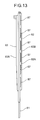
- the side plate 7 in this case refers to the one on the left in the Fig. 12 as observed facing the drawing, unless otherwise specified, in which case the side plate 7 on the right is referred to.
- the right and left side plates 7 are laterally symmetrical and basically share the same structure.
- the side plate 7 is constructed by an enforcing plate 81 for vertical enforcement, and an outer plate 82 and an inner plate 83 that are composed of a transparent hard synthetic resin.
- the configurations of the bottom edges of the outer plate 82 and the inner plate 83 are substantially matched to the configuration of the upper surface of the unit base 3.
- the front surfaces of these two plates are shaped so that they gently curve from the top plate 8 down toward the front portion of the unit 3 base located at bottom front, thus covering a side surface of the display compartment 13.
- the enforcing plate 81 penetrates notches 3B at the rear on both sides of the unit base 3, enters into the machine chamber 14, and is screwed to the unit base 3 or the rear portion of the bracket 16.
- the top plate 8 is coupled to the upper edges of the enforcing plates 81 and 81.
- the outer plate 82 and the inner plate 83 are joined to each other with the enforcing plate 81 sandwiched therebetween at the back thereof.
- the peripheral edge portions of these plates are fastened to each other, and the enforcing plate 81 is screwed.
- an air layer G is formed between the outer plate 82 and the inner plate 83, improving the adiabatic effect.
- the portions of the outer plate 82 and the inner plate 83 that cover the enforcing plate 81 are provided with projecting portions 82A and 83A that vertically project outward.
- An exhaust duct 86 vertically extending is formed between the projecting portion 82A of the outer plate 82 and the enforcing plate 81.
- the bottom end of the exhaust duct 86 is in communication with the interior of the machine chamber 14, and the top end thereof is closed by the top plate 8.
- a plurality of exhaust ports 87 are formed vertically in a front surface 82B of the projecting portion 82A, which provides the front surface of the exhaust duct 86.
- aspirators 88 for preventing the air layer G from becoming cloudy are punched in the inner plate 83.
- the exhaust duct 86 located between the enforcing plate 81 and the outer plate 82 is opened upward before the top plate 8 is installed, as shown in Fig. 10; hence, a colored strip of plate or a strip of panel carrying an advertising display may be inserted between the projecting portion 82A and the enforcing plate 81 through the open end of the exhaust duct. This arrangement enables the appearance and sales promotion effect to be improved.
- the projecting portion 83A of the inner plate 83 has a plurality of shelf holders 89 slightly inclining downward toward the front, as shown in Fig. 12.
- the shelf holders 89 are integrally formed in four vertical stages.
- the shelf holders 89 are opened toward the opposing side plates 7 and toward the back, and a shelf 91 made of a transparent hard resin is inserted through the opening 9 in the rear surface.
- the shelf 91 is hung in the display compartment 13, as illustrated in Fig. 5.
- the plane fluorescent lamp 31 includes a glass vessel composed of a formed glass member 141 and a sheet glass 142, and phosphors 143 and 143 are disposed on the inner bottom surface and the inner top surface of the glass vessel.
- discharging electrodes 144 and 144 are disposed on a pair of opposing side surfaces in the glass vessel, electrode lead wires (not shown) being connected to the discharging electrodes 144 and 144.
- the interior of the glass vessel is substantially vacuum, and a very small amount of mercury vapor (Hg) or a very small amount of a rare gas, such as argon (Ar) is sealed in the glass vessel.
- An AC power source is connected to the electrode lead wires through wiring (not shown) to effect discharge between the discharging electrodes 144 and 144.
- This causes accelerated electrons 146 to collide with the mercury (Hg) or argon (Ar) molecules and to change the energy level from the normal state to the excited state.
- the excited molecules or atoms radiate ultraviolet rays peculiar to the individual molecules when they restore their normal state.
- the ultraviolet rays bump against the phosphors 143 and 143 and are discharged in the form of visible light rays through the surface of the sheet glass 142. This enables the surface of the plane fluorescent lamp 31 to provide a predetermined level of illuminance in, for example, a milky color.
- the plane fluorescent lamp 31 measures, for example, 50 mm deep, 300 mm wide, and about 10 mm thick. A plurality of the plane fluorescent lamps 31 may be disposed side by side in a line, depending on a place where they are installed. The plane fluorescent lamp 31 may, however, take any size if the strength thereof is not important.
- the plane fluorescent lamp 31 is thin, namely, about 10 mm thick, permitting itself to be installed in a much smaller space than a space used to be required for installing a conventional type of fluorescent lamp. Hence, the space in the display compartment 13 can be increased.
- the plane fluorescent lamp 31 emits milky light rays from its surface, obviating the need for providing a separate shade on the front, with a resultant reduction in cost.
- a card carrying characters or a shade in a desired color may be installed on the front surface of the plane fluorescent lamp 31 for ornamental purpose to improve product display sales effect, thereby promoting customers' appetite for buying the products.
- the plane fluorescent lamp 31 is also advantageous in that it exhibits good low-temperature properties as compared with conventional fluorescent lamps, so that its illuminance is not affected even in a relatively low-temperature environment, such as in a low-temperature showcase.
- the plane fluorescent lamp 31 is also advantageous from the safety viewpoint, because the surface of the plane fluorescent lamp 31 does not become hot, so that there will be no problem in that customers, employees, etc. get burns on their hands or fingers from accidental touch to the fluorescent lamp. Moreover, the plane fluorescent lamp 31 does not add to heat load, contributing to improved cooling efficiency. The plane fluorescent lamp 31 does not have a temperature difference between its ON mode and OFF mode, making it possible to prevent dews from being produced on its surface. This arrangement obviates the need for installing a heater as a heat generating member for preventing dews, as in a conventional art, thus allowing a reduction in cost.
- the plane fluorescent lamp 31 has a markedly longer service life than that of a standard fluorescent lamp, requiring no frequent maintenance work, such as replacing old fluorescent lamps failing to properly stay ON.
- the shelf 91a shaped like a box is formed by injection-molding a polystyrene (PS) resin, and has the riser flange 92a for restraining products from falling at its front, a semicircular protuberance 94a being formed on the front top portion of the riser flange 92a.
- the price rail 93a is formed by extrusion molding by using a transparent ABS resin.
- An insertion portion 97a is constituted by a display portion 95a having a curved front surface and a supporting portion 106a that is located close to the rear side of the display portion to clamp a price card 96a in cooperation with the display portion 95a.
- a locking portion 98a is formed at the rear of the insertion portion 97a.
- the locking portion 98a that supports the riser flange 92a of the shelf 91a by sandwiching it from the front and back is locked onto the shelf 91a.
- the top edge of the display portion 95a provides an abutting portion 99a positioned above the riser flange 92a of the shelf 91a.
- the locking portion 98a also has a curved recessed portion 100a located at a position associated with the protuberance 94a of the shelf 91a mentioned above.
- the price card 96a is composed of a piece of paper or a resin sheet on which a price or a product name has been printed.
- a member that is slightly longer in the longitudinal direction than the supporting portion 106a of the insertion portion 97a of the price rail 93a is prepared, and inserted in the insertion portion 97a of the price rail 93a. Then, the price rail 93a is inserted from above the shelf 91a.
- the price card 96a is slightly longer than the supporting portion 106a of the insertion portion 97a; hence, the price card 96a can be removed by pulling it up while pushing the portion slightly extending upward beyond the supporting portion 106a from the back of the abutting portion 99a by a finger, and replaced by another desired price card 96a having a different product name or price printed thereon.
- the showcase 1 constructed as described above is rested on the cash register counter C of a convenience store, as shown in Fig. 15.
- a product V such as a bottled or canned beverage is accommodated and displayed in the display compartment 13.
- the product V is put in the display compartment from the opening 12 on the front and placed on the low portion 6A on the front side of the longitudinal wall portion 6C of the bottom plate 6.
- the low portion 6A provides the display surface of the lowermost stage.
- the product V leans against the protuberance 27 or the discharge guide 26 at the back rather than falling toward the front.
- the door 11 on the rear surface is opened and the product V is put in the display compartment through the opening 9.
- the high portion 6B and the shelf 91 are slightly inclined downward toward the front, the products V can be smoothly accommodated in succession from the rear.
- the high portion 6B and the shelf 91 are inclined downward toward their front, customers can see the products V more easily, and when a customer takes out the product V on the front row, the product V behind it will be automatically moved to the front row.
- the plane fluorescent lamp 31 When the power of the showcase is turned ON to start operation, the plane fluorescent lamp 31 will first turns ON to light up advertisement characters or the like at the front, while illuminating the interior of the display compartment 13 at the rear at the same time.
- the compressor 63, the motor 19M of the blower 19, and the condenser blower 69 are actuated, a gas refrigerant of high temperature and pressure discharged from the discharging pipe 63D of the compressor 63 flows into the condenser 64 wherein it is condensed and liquefied by outside air supplied by the condenser blower 69.
- the condensed liquefied refrigerant is decompressed by the capillary tube 66, then passed into the cooler 18 where it evaporates.
- the refrigerant deprives the air in the cooling chamber 17 of heat, thereby exhibiting its cooling effect.
- the refrigerant leaving the cooler 18 is suctioned into the compressor 63 through the intake pipe 63S, and compressed again.
- the cold air in the cooling chamber 17 that has been cooled by performing heat exchange with the cooler 18 goes out through the communication aperture 32 and enters into the rear duct 41 through the communication aperture 43.
- the cold air then moves up in the rear duct 41 and enters the top duct 51 through the communication apertures 42 and 53, and moves forward. Thereafter, the cold air is discharged from the discharge port 61 toward the front opening 12 of the display compartment 13.
- the cold air discharged from the discharge port 61 moves toward the inlet 29 while forming an air curtain at the opening 12, and is suctioned into the inlet 29 by the suction force of the blower 19 by being guided by the plane fluorescent lamp 31.
- a part of the air curtain is circulated in the display compartment 13 to cool the interior of the display compartment 13 to a predetermined temperature.
- a part of the cold air leaving the cooler 18 enters the lower discharge duct 23, moves forward therein, and is discharged to the front of the longitudinal wall portion 6C from the lower discharge port 22.
- the display portion 95a on the front surface of the price rail 93a is curved, so that the flow of the aforesaid air curtain formed at the opening 12 can smoothly moves toward the inlet 29 without being blocked.
- the cooling effect on the low portion 6A of the display surface of the lowermost stage which is located farther from the discharge port 61 tends to deteriorate.
- the cold air is directly supplied from the lower discharge port 22, thereby solving the deteriorated cooling effect problem.
- the lower discharge port 22 is provided with the discharge guide 26, and the protuberance 27 is formed therebelow; hence, the discharge of the cold air from the lower discharge port 22 or the circulation of the cold air will not be interfered with by the product V on the low portion 6A.
- Height L1 from the bottom surface, that is, the installation surface, of the unit base 3 of the showcase 1 to the upper surface of the top plate 8 is set to 700 mm to 750 mm (715 mm in this embodiment), and height L2 to the display surface of the lowermost stage (the low portion 6A) is set to a value within a range of 100 mm to 200 mm (149 mm in this embodiment).
- Height L3 from the installation surface to the upper edge of the plane fluorescent lamp 31 is set to 200 mm to 210 mm (205 mm in this embodiment), and height L4 from the installation surface to the display surface of the middle stage (the high portion 6B) is set to a value within the range of 300 mm to 400 mm (304 mm in this embodiment).
- height L5 from the installation surface to the display surface of the uppermost stage (the shelf 91) is set to a value within the range of 400 mm to 700 mm (489 mm in this embodiment), and height L6 from the installation surface to the front edge of the top plate 8 is set to a value within the range of 650 mm to 700 mm (668 mm in this embodiment).
- Longitudinal dimension L7 of the showcase 1 is set to a value within the range of 450 mm to 550 mm (490 mm in this embodiment).
- a typical height of the cash register counter C provided at a convenience store ranges from 800 mm to 1000 mm, and a typical depth thereof is about 550 mm. Therefore, the showcase 1 in accordance with the present invention can be stably installed on the cash register counter C, and is capable of displaying the product V while cooling the product V in the display compartment 13. This makes it possible to promote customers' appetite for buying the products V, such as bottled or canned beverages, that are preferably sold especially in the vicinity of the cash register counter C, thus contributing to increased sales.
- the height from the floor to the display surface of the lowermost stage ranges from 900 mm to 1200 mm.
- This range of height of the display surface of the lowermost stage (the low portion 6A) corresponds to the range of the height of the waists to chests of most customers, allowing the visibility of the product V on the lowermost stage to be improved and also enabling customers to easily take out the product V.
- the height of the display surface of the middle stage (the high portion 6B) and the height of the display surface of the uppermost stage (the shelf 91, or the high portion 6B if the shelf 91 is not installed) from the installation surface range from 300 mm to 700 mm.
- the height from the floor to the display surface of the uppermost stage (the shelf 91 or the high portion 6B) ranges from 1100 mm to 1700 mm.
- This height range of the display surface of the uppermost stage approximately corresponds to the height range of customers' bellies to faces, leading to improved visibility of the product V on the uppermost stage and also enabling customers to easily take out the product V.
- the machine chamber 14 is configured to have the lower front and the higher back by the stepped configuration of the adiabatic wall 4.
- the display surface of the lowermost stage (the low portion 6A) can be set low, while allowing the bulky units, such as the compressor 63 and the condenser 64, to be installed at the back in the machine chamber 14.
- the hot air coming out of the notches 3B flows along the outer surface of the outer plate 82 at the bottom of the side plate 7 to heat a portion in the vicinity of the inlet 29 that is apt to have dews, thereby preventing the dews.
- the hot air flowing into the exhaust duct 86 rises therein and eventually moves out toward the outer surface of the outer plate 82 at the front through the exhaust ports 87 in the front surface, as shown in Fig. 10.
- the top end of the exhaust duct 86 is closed by the top plate 8, so that the pressure (static pressure) at the upper portion of the exhaust duct 86 rises, and the volume of hot air flowing out increases in higher exhaust ports 87. Therefore, the hot air is preferentially supplied to the upper portion of the outer surface of the outer plate 82 which is near the discharge port 61 and where dews are most likely to appear, thus allowing the dew problem to be effectively solved.
- the abutting portion 99a forming the upper edge of the display portion 95a of the price rail 93a is positioned above the riser flange 92a of the shelf 91a, causing the front surface of the product V to abut against the abutting portion 99a.
- This means that the product is supported at above the riser flange 92a of the shelf 91a, minimizing the chance of the product falling off the shelf 91a. If the shelf 91a inclines downward toward the front, then even if the product V slips down on the shelf 91a and inclines forward, the product is pushed back by the abutting portion 99a.
- the display portion 95a of the price rail 93a is curved and its bottom edge abuts against the bottom edge of the riser flange 92a; hence, even if the product V bumps against the abutting portion 99a with momentum, the deformation of the display portion 95a can be minimized, and the effect for preventing the product V from falling forward can be further enhanced.
- the price card 96a is hardly exposed because it is inserted in the insertion portion 97a of the price rail 93a, and the upper edge portion of the price rail 93a covers the top of the price card 96a, the price card 96a is scarcely soiled by dust or the like. Even when the price card 96a is formed of such a material as paper or the like, the price card 96a will be able to survive an extended use.
- FIG. 17 shows a second embodiment in accordance with the present invention.
- a box-shaped shelf 91b is formed by injection molding by using a polystyrene (PS) resin.
- the shelf 91b has a riser flange 92b at its front, and a semicircular protuberance 94b is formed on the front upper portion of the riser flange 92b.
- a rectangular aperture 102b is formed in the front of the shelf 91b, and a plane fluorescent lamp 101 is provided in association with the rectangular aperture 102b.
- the plane fluorescent lamp 101 has the same configuration as that of the plane fluorescent lamp 31 set forth above.
- the plane fluorescent lamp 101 is surrounded by a securing member 103b formed by injection molding by using a transparent resin.
- the securing member 103b is transparent for about 10 mm inward from the outer peripheral edge portions of the top and bottom surfaces thereof. Except for the transparent portion, the remainder of the securing member 103b is formed of a translucent portion 104b with a crimp pattern indicated by a broken line in the drawing, so that the discharging electrodes 144, etc. in the plane fluorescent lamp 101 are invisible from outside.
- the plane fluorescent lamp 101 is secured to the shelf 91b by a screw 105, the plane fluorescent lamp extends over the resting surface of the shelf 91b, and the top surface of the securing member 103b of the plane fluorescent lamp 101 becomes flush with the bottom surface of the shelf 91b.
- the price rail 93b is formed by extrusion molding by using a transparent ABS resin.
- An insertion portion 97b is constituted by a display portion 95b having a curved front surface and a supporting portion 106b that is located close to the rear side of the display portion to clamp a price card 96b in cooperation with the display portion 95b.
- a locking portion 98b is formed at the rear of the insertion portion 97b.
- the locking portion 98b that supports the riser flange 92b of the shelf 91b by sandwiching it from the front and back is locked onto the shelf 91b.
- the top edge of the display portion 95b provides an abutting portion 99b positioned above the riser flange 92b of the shelf 91b, which is the same as the first embodiment.
- the locking portion 98b also has a curved recessed portion 100b located at a position associated with the protuberance 94b of the shelf 91b mentioned above.
- the top surface of the securing member 103b of the plane fluorescent lamp 101 is flush with the bottom surface of the shelf 91b, allowing products to be rested thereon.
- the plane fluorescent lamp 101 emits light upward and downward at the same time.
- the plane fluorescent lamp 101 is close to products, so that the illuminance on the products rested on the shelf 91b where the plane fluorescent lamp 101 is provided and the illuminance on the products rested on the bottom plate 6 located under the shelf 91b are both improved. This will promote customers' appetite for buying the products, permitting contribution to an increased sales.
- the products are supported by the abutting portion 99b of the price rail 93b that is located above the riser flange 92b of the shelf 91b, thus minimizing the chance of the products falling off the shelf 91b.
- the shelf 91b is inclined downward toward the front, the effect for preventing the products from falling will be further enhanced.
- the price card 96b is hardly exposed because it is inserted in the insertion portion 97b of the price rail 93b, and the upper edge portion of the price rail 93b covers the top of the price card 96b; hence, the price card 96a is hardly soiled by dust or the like, enabling the price card 96b to survive an extended use.
- the front surface of the shelf 91b is covered by the display portion 95b to make the riser flange 92b and the plane fluorescent lamp 101 invisible.
- FIG. 18 and Fig. 19 show a third embodiment in accordance with the present invention.
- a box-shaped shelf 91c is formed by injection molding by using a transparent or translucent polystyrene (PS) resin.
- the shelf 91c has a riser flange 92c at its front, and a semicircular protuberance 94c is formed on the front upper portion of the riser flange 92c.
- the same plane fluorescent lamp 101 as that mentioned above is provided at the front bottom of the shelf 91c.
- the plane fluorescent lamp 101 is surrounded by a securing member 103c formed by injection molding by using a transparent resin.
- the securing member 103c is transparent for about 10 mm inward from the outer peripheral edge portions of the top and bottom surfaces thereof.
- the remainder of the securing member 103c is formed of a translucent portion 104c with a crimp pattern indicated by a broken line in the drawing, so that the discharging electrodes 144, etc. in the plane fluorescent lamp 101 are invisible from outside.
- the plane fluorescent lamp 101 is secured to the front bottom portion of the shelf 91c by a screw 105.
- a price rail 93c is formed by extrusion molding by using a transparent ABS resin.
- An insertion portion 97c is constituted by a display portion 95c having a curved front surface and a supporting portion 106c that is located close to the rear side of the display portion to clamp a price card 96c in cooperation with the display portion 95c.
- a locking portion 98c is formed at the rear of the insertion portion 97c.
- the locking portion 98c that supports the riser flange 92c of the shelf 91c by sandwiching it from the front and back is locked onto the shelf 91c.
- an abutting portion 99c on the top edge of the display portion 95c is positioned behind the riser flange 92c of the shelf 91c.
- the locking portion 98c also has a curved recessed portion 100c located at a position associated with the protuberance 94c of the shelf 91c mentioned above.
- the product V is supported by the abutting portion 99c of the price rail 93c located above the riser flange 92c of the shelf 91c, so that the chance of the product falling off the shelf 91c is minimized.
- the abutting portion 99c of the price card 96c is located behind the riser flange 92c of the shelf 91c, the front surface of the product V is positioned at the back. Therefore, the light is radiated from the front of the plane fluorescent lamp 101 to the front surface of the product V, thus improving the illuminance on the front surface or a display (product label) of the product V. This will promote customers' appetite for buying the product, leading to an increase in sales.
- the plane fluorescent lamp 101 emits light upward and downward at the same time. Moreover, the plane fluorescent lamp 101 is close to the product V, so that the illuminance on the products rested on the shelf 91c where the plane fluorescent lamp 101 is provided and the illuminance on the products rested on the bottom plate 6 located under the shelf 91c are both improved. Furthermore, as in the case of the first embodiment, the product V is supported by the abutting portion 99c of the price rail 93c that is located above the riser flange 92c of the shelf 91c, thus minimizing the chance of the products falling off the shelf 91c. If the shelf 91c is inclined downward toward the front, the effect for preventing the products from falling will be further enhanced.
- the price card 96c is scarcely exposed because it is inserted in the insertion portion 97c of the price rail 93c, and the upper edge portion of the price rail 93c covers the top of the price card 96c; hence, the price card 96c is scarcely soiled by dust or the like, enabling the price card 96c to survive an extended use.
- Fig. 20 shows a state wherein the price rail 93b has been removed from the second embodiment shown in Fig. 17.
- the top surface of the securing member 103b of the plane fluorescent lamp 101 becomes flush with the bottom surface of the shelf 91b, and products can be rested thereon, as in the case of the second embodiment.
- the plane fluorescent lamp 101 emits light upward and downward at the same time, and the plane fluorescent lamp 101 is close to the product V, so that the illuminance on the products rested on the shelf 91b where the plane fluorescent lamp 101 is provided and the illuminance on the products rested on the bottom plate 6 located under the shelf 91b are both improved. This will promote customers' appetite for buying the product V, enabling increased sales to be achieved.
- the showcase according to the present invention allows prolonged use of price cards even if they are made of, for example, paper or the like, by protecting the price cards from being soiled by dust or the like, by preventing the price cards from being lost, prevents products from falling off a shelf, and improves the illuminance on products by a plane fluorescent lamp provided on a shelf to promote customers' appetite for buying, thereby contributing to increased sales.
Landscapes
- Physics & Mathematics (AREA)
- Thermal Sciences (AREA)
- Devices That Are Associated With Refrigeration Equipment (AREA)
- Freezers Or Refrigerated Showcases (AREA)
- Display Racks (AREA)
- Cold Air Circulating Systems And Constructional Details In Refrigerators (AREA)
Applications Claiming Priority (2)
| Application Number | Priority Date | Filing Date | Title |
|---|---|---|---|
| JP2000015931 | 2000-01-25 | ||
| JP2000015931A JP2001204600A (ja) | 2000-01-25 | 2000-01-25 | ショーケース |
Publications (2)
| Publication Number | Publication Date |
|---|---|
| EP1120069A1 true EP1120069A1 (de) | 2001-08-01 |
| EP1120069B1 EP1120069B1 (de) | 2004-08-25 |
Family
ID=18543150
Family Applications (1)
| Application Number | Title | Priority Date | Filing Date |
|---|---|---|---|
| EP20010300149 Expired - Lifetime EP1120069B1 (de) | 2000-01-25 | 2001-01-09 | Schaukasten |
Country Status (5)
| Country | Link |
|---|---|
| EP (1) | EP1120069B1 (de) |
| JP (1) | JP2001204600A (de) |
| CN (1) | CN1146337C (de) |
| DE (1) | DE60105071T2 (de) |
| SG (1) | SG90229A1 (de) |
Cited By (5)
| Publication number | Priority date | Publication date | Assignee | Title |
|---|---|---|---|---|
| GB2423464A (en) * | 2005-02-28 | 2006-08-30 | Red Bull Company Ltd | A display tray |
| EP1961342A1 (de) * | 2007-02-26 | 2008-08-27 | Sanyo Electric Co., Ltd. | Schaukasten |
| US20210298492A1 (en) * | 2018-08-20 | 2021-09-30 | Wirth Research Limited | A Refrigerated Display Case |
| US20220232999A1 (en) * | 2019-07-05 | 2022-07-28 | Aerofoil Energy Limited | Bracket for use with open display refrigerators |
| US12082717B1 (en) | 2019-08-15 | 2024-09-10 | Aerofoil Energy Limited | Air guide brackets for refrigerators |
Families Citing this family (4)
| Publication number | Priority date | Publication date | Assignee | Title |
|---|---|---|---|---|
| JP2007082779A (ja) * | 2005-09-22 | 2007-04-05 | Okamura Corp | 滑り性に優れた商品陳列棚の棚板 |
| JP5853161B2 (ja) * | 2011-04-28 | 2016-02-09 | パナソニックIpマネジメント株式会社 | オープンショーケース |
| US9138076B2 (en) * | 2014-01-24 | 2015-09-22 | Rtc Industries, Inc. | Product management display system |
| JP2016047113A (ja) * | 2014-08-27 | 2016-04-07 | 凸版印刷株式会社 | 表示パネルおよび大型表示パネル |
Citations (6)
| Publication number | Priority date | Publication date | Assignee | Title |
|---|---|---|---|---|
| US1991216A (en) * | 1930-09-25 | 1935-02-12 | Herbert B Hyams | Display device |
| US2214239A (en) * | 1937-11-27 | 1940-09-10 | Harry E Young | Showcase |
| CH672691A5 (en) * | 1987-06-22 | 1989-12-15 | Raalte Tom J A | Label holder for attaching to sales display stands - is made from strip of transparent material with folded edges |
| DE29717444U1 (de) * | 1997-09-30 | 1998-01-08 | Austria Haustechnik Ag, Rottenmann | Infrarotfreie und ultraviolettfreie Beleuchtung von in einem Kühlmöbel gekühlten Waren |
| DE29813767U1 (de) * | 1998-08-01 | 1998-11-05 | Hertel, Günther, 90491 Nürnberg | Warentheke |
| WO2000054632A1 (en) * | 1999-03-18 | 2000-09-21 | Chesapeake Display And Packaging Company | Display system for advancing products |
-
2000
- 2000-01-25 JP JP2000015931A patent/JP2001204600A/ja active Pending
- 2000-12-25 CN CNB001364324A patent/CN1146337C/zh not_active Expired - Fee Related
-
2001
- 2001-01-09 DE DE2001605071 patent/DE60105071T2/de not_active Expired - Fee Related
- 2001-01-09 EP EP20010300149 patent/EP1120069B1/de not_active Expired - Lifetime
- 2001-01-19 SG SG200100300A patent/SG90229A1/en unknown
Patent Citations (6)
| Publication number | Priority date | Publication date | Assignee | Title |
|---|---|---|---|---|
| US1991216A (en) * | 1930-09-25 | 1935-02-12 | Herbert B Hyams | Display device |
| US2214239A (en) * | 1937-11-27 | 1940-09-10 | Harry E Young | Showcase |
| CH672691A5 (en) * | 1987-06-22 | 1989-12-15 | Raalte Tom J A | Label holder for attaching to sales display stands - is made from strip of transparent material with folded edges |
| DE29717444U1 (de) * | 1997-09-30 | 1998-01-08 | Austria Haustechnik Ag, Rottenmann | Infrarotfreie und ultraviolettfreie Beleuchtung von in einem Kühlmöbel gekühlten Waren |
| DE29813767U1 (de) * | 1998-08-01 | 1998-11-05 | Hertel, Günther, 90491 Nürnberg | Warentheke |
| WO2000054632A1 (en) * | 1999-03-18 | 2000-09-21 | Chesapeake Display And Packaging Company | Display system for advancing products |
Cited By (6)
| Publication number | Priority date | Publication date | Assignee | Title |
|---|---|---|---|---|
| GB2423464A (en) * | 2005-02-28 | 2006-08-30 | Red Bull Company Ltd | A display tray |
| EP1961342A1 (de) * | 2007-02-26 | 2008-08-27 | Sanyo Electric Co., Ltd. | Schaukasten |
| US7572025B2 (en) | 2007-02-26 | 2009-08-11 | Sanyo Electric Co., Ltd. | Showcase |
| US20210298492A1 (en) * | 2018-08-20 | 2021-09-30 | Wirth Research Limited | A Refrigerated Display Case |
| US20220232999A1 (en) * | 2019-07-05 | 2022-07-28 | Aerofoil Energy Limited | Bracket for use with open display refrigerators |
| US12082717B1 (en) | 2019-08-15 | 2024-09-10 | Aerofoil Energy Limited | Air guide brackets for refrigerators |
Also Published As
| Publication number | Publication date |
|---|---|
| JP2001204600A (ja) | 2001-07-31 |
| DE60105071T2 (de) | 2005-08-11 |
| CN1306791A (zh) | 2001-08-08 |
| EP1120069B1 (de) | 2004-08-25 |
| CN1146337C (zh) | 2004-04-21 |
| DE60105071D1 (de) | 2004-09-30 |
| SG90229A1 (en) | 2002-07-23 |
Similar Documents
| Publication | Publication Date | Title |
|---|---|---|
| US6276810B1 (en) | Rack lamp | |
| JP4049486B2 (ja) | ショーケース | |
| EP1120069B1 (de) | Schaukasten | |
| JP2983847B2 (ja) | ショーケース | |
| EP1129649A2 (de) | Schaukasten | |
| JP2007175130A (ja) | オープンショーケース | |
| JP3889537B2 (ja) | オープンショーケース | |
| JP2002364974A (ja) | ショーケース | |
| JP2002165678A (ja) | ショーケース | |
| JP5526815B2 (ja) | 自動販売機の商品見本展示装置 | |
| JP2001263933A (ja) | ショーケース | |
| JPH07308246A (ja) | ショーケース | |
| JPH09285369A (ja) | ショーケースの商品陳列棚 | |
| JP2001133133A (ja) | オープンショーケース | |
| JP2005299964A (ja) | ショーケース | |
| JP2001017288A (ja) | オープンショーケース | |
| JPH05317146A (ja) | ショーケースの照明装置 | |
| JP2001133122A (ja) | オープンショーケース | |
| JP3725404B2 (ja) | ショーケース | |
| JP3059895B2 (ja) | オープンショーケース | |
| JP3889664B2 (ja) | ショーケース | |
| JPH0972654A (ja) | 棚装置 | |
| KR19990037265U (ko) | 쇼케이스 | |
| JP3710954B2 (ja) | 低温ショーケース | |
| JPH08114377A (ja) | 冷蔵ショーケース |
Legal Events
| Date | Code | Title | Description |
|---|---|---|---|
| PUAI | Public reference made under article 153(3) epc to a published international application that has entered the european phase |
Free format text: ORIGINAL CODE: 0009012 |
|
| AK | Designated contracting states |
Kind code of ref document: A1 Designated state(s): AT BE CH LI Kind code of ref document: A1 Designated state(s): DE FR GB |
|
| AX | Request for extension of the european patent |
Free format text: AL;LT;LV;MK;RO;SI |
|
| 17P | Request for examination filed |
Effective date: 20020118 |
|
| AKX | Designation fees paid |
Free format text: AT BE CH LI |
|
| RBV | Designated contracting states (corrected) |
Designated state(s): DE FR GB |
|
| REG | Reference to a national code |
Ref country code: DE Ref legal event code: 8566 |
|
| 17Q | First examination report despatched |
Effective date: 20030807 |
|
| GRAP | Despatch of communication of intention to grant a patent |
Free format text: ORIGINAL CODE: EPIDOSNIGR1 |
|
| GRAS | Grant fee paid |
Free format text: ORIGINAL CODE: EPIDOSNIGR3 |
|
| GRAA | (expected) grant |
Free format text: ORIGINAL CODE: 0009210 |
|
| AK | Designated contracting states |
Kind code of ref document: B1 Designated state(s): DE FR GB |
|
| REG | Reference to a national code |
Ref country code: GB Ref legal event code: FG4D |
|
| REF | Corresponds to: |
Ref document number: 60105071 Country of ref document: DE Date of ref document: 20040930 Kind code of ref document: P |
|
| ET | Fr: translation filed | ||
| PLBE | No opposition filed within time limit |
Free format text: ORIGINAL CODE: 0009261 |
|
| STAA | Information on the status of an ep patent application or granted ep patent |
Free format text: STATUS: NO OPPOSITION FILED WITHIN TIME LIMIT |
|
| 26N | No opposition filed |
Effective date: 20050526 |
|
| PGFP | Annual fee paid to national office [announced via postgrant information from national office to epo] |
Ref country code: DE Payment date: 20090102 Year of fee payment: 9 |
|
| PGFP | Annual fee paid to national office [announced via postgrant information from national office to epo] |
Ref country code: GB Payment date: 20090107 Year of fee payment: 9 |
|
| PGFP | Annual fee paid to national office [announced via postgrant information from national office to epo] |
Ref country code: FR Payment date: 20090113 Year of fee payment: 9 |
|
| GBPC | Gb: european patent ceased through non-payment of renewal fee |
Effective date: 20100109 |
|
| REG | Reference to a national code |
Ref country code: FR Ref legal event code: ST Effective date: 20100930 |
|
| PG25 | Lapsed in a contracting state [announced via postgrant information from national office to epo] |
Ref country code: FR Free format text: LAPSE BECAUSE OF NON-PAYMENT OF DUE FEES Effective date: 20100201 |
|
| PG25 | Lapsed in a contracting state [announced via postgrant information from national office to epo] |
Ref country code: DE Free format text: LAPSE BECAUSE OF NON-PAYMENT OF DUE FEES Effective date: 20100803 |
|
| PG25 | Lapsed in a contracting state [announced via postgrant information from national office to epo] |
Ref country code: GB Free format text: LAPSE BECAUSE OF NON-PAYMENT OF DUE FEES Effective date: 20100109 |