EP1119071A2 - Dispositif de liaison d'une vitre avec des fonctions électriques - Google Patents
Dispositif de liaison d'une vitre avec des fonctions électriques Download PDFInfo
- Publication number
- EP1119071A2 EP1119071A2 EP01400122A EP01400122A EP1119071A2 EP 1119071 A2 EP1119071 A2 EP 1119071A2 EP 01400122 A EP01400122 A EP 01400122A EP 01400122 A EP01400122 A EP 01400122A EP 1119071 A2 EP1119071 A2 EP 1119071A2
- Authority
- EP
- European Patent Office
- Prior art keywords
- glass
- contact
- contact element
- window
- connection device
- Prior art date
- Legal status (The legal status is an assumption and is not a legal conclusion. Google has not performed a legal analysis and makes no representation as to the accuracy of the status listed.)
- Granted
Links
Images

Classifications
-
- H—ELECTRICITY
- H01—ELECTRIC ELEMENTS
- H01Q—ANTENNAS, i.e. RADIO AERIALS
- H01Q1/00—Details of, or arrangements associated with, antennas
- H01Q1/27—Adaptation for use in or on movable bodies
- H01Q1/32—Adaptation for use in or on road or rail vehicles
-
- H—ELECTRICITY
- H01—ELECTRIC ELEMENTS
- H01Q—ANTENNAS, i.e. RADIO AERIALS
- H01Q1/00—Details of, or arrangements associated with, antennas
- H01Q1/12—Supports; Mounting means
- H01Q1/1271—Supports; Mounting means for mounting on windscreens
-
- H—ELECTRICITY
- H01—ELECTRIC ELEMENTS
- H01Q—ANTENNAS, i.e. RADIO AERIALS
- H01Q1/00—Details of, or arrangements associated with, antennas
- H01Q1/12—Supports; Mounting means
- H01Q1/1271—Supports; Mounting means for mounting on windscreens
- H01Q1/1278—Supports; Mounting means for mounting on windscreens in association with heating wires or layers
Definitions
- the invention relates to a device for connecting a window glass, in particular a window glass for a window motor vehicle, with electrical functions presenting the characteristics of the preamble of the claim 1.
- Document DE-C1 195 36 131 discloses a window antenna diversity with connecting elements, which is used preferably for vehicles.
- the antenna elements respectively the antenna conductor structures are deposited on the surface of a window by screen printing and are cooked when the glass is heated before it is tempered.
- Each antenna is provided with several antennas on the same window, in order to be able to use different directions of receiving incident transmitters and selecting automatically each time the transmitter having the intensity of optimal field.
- faces of connection of individual antennas are locally grouped in one place in the edge area of the window.
- a contact element multiple in the form of a special flat cable section, which has a counter-contact for each connection face in addition to the corresponding conductor.
- the signals electrical antennas are transmitted by these conductors to the respective amplifiers arranged at a distance from the window.
- Simple AM / FM antennas have been produced for several years on windshields, side windows or rear glasses either by placing metal wires in windscreens in laminated safety glass either by conductive structures screen printed on glass single window security for side or rear windows. Preferred forms of implementation also use the rear sunglasses heating range to make one antenna.
- plug connectors are also frequently used or spring contacts.
- the future development of the information needs of the driver of the vehicle with increasing density of traffic leads to the networking of different systems with the objective of intelligently managing the flow of vehicles in such a way that for example the exact position determination possible with the Aglobal positioning system @ (GPS) in combination with automatic planning of the route and stationary facilities for measuring traffic flow allows optimal pursuit of the goal.
- GPS Aglobal positioning system @
- the future role of the driver of the vehicle as an active and passive participant in a wide wireless information and communication network involves the development of on-board reception systems correspondents, who activate information systems in the vehicle. These reception systems include integrated antenna systems for individual communication including necessary electronics amplifiers, respectively adapters impedance.
- the information systems currently used in vehicles are AM and FM radio transmitters, UHF video, GSM phone as well as GPS navigation. Until now, these are linked to the individual networks in part by separate stick, sphere or increasing.
- a position of the antenna systems on the rear window or window rear is optimal for compatibility reasons electromagnetic, while they should preferably be installed in the windshield in vehicles with the rear central engine and also with bodywork variables.
- All systems must meet the requirement of a panoramic reception as little disturbed as possible. This is not allowed, however, with antenna structures two-dimensional, only by the fact that in each position of the vehicle, the optimal position of the antenna with the signal the strongest is selected using a controller diversity by several antennas located in different positions on the glass (diversity system) and be introduced in on-board information systems.
- the number of individual diversity systems required depends on the geometric configuration, compatibility vehicle-specific electromagnetic and possibility obtain high signal intensities by mixing signals (phase-amplitude sum).
- connection systems to be used must meet severe industry requirements automotive weather and weather stability temperature as well as resistance to vibrations etc.
- the antenna amplifier and the impedance adapter should be positioned too as close as possible to the individual antenna bases, to guarantee as good a reception as possible with large margin of protection.
- said antenna bases must be arranged at relatively large distances from each other on the face of the glass, because, especially in systems diversity, there is a strong dependence between the intensity of detectable field on a glass antenna and the direction of influence of the transmitter concerned.
- a glass antenna system (DE-A1 39 11 178), in which electrical components are installed directly on, in or near a vehicle window and the set of antenna signals and voltages power supplied by a single bundle of cables composed of high frequency conductors and lines feed.
- a glass antenna which can be installed as a complete unit in the vehicle body and which is electrically connected to the bodywork, respectively to the network linked to the bodywork, only by a single multiple connection in the form of a bundle of cables.
- Amplifiers antenna (Aquadripoles @) of this system are however fixed directly on the glass and soldered with the input lines and output produced thereon by screen printing.
- the object of the invention is to propose a device for connection, which simplifies the connection of electrical functions arranged on a window with several connection faces arranged in a decentralized manner, in particular antenna elements, with sets that follow.
- the connecting faces of the elements functional electrics are distributed along the edge of the glass, especially in its corner areas. So, longer connection conductors disappear from the glass itself in relation to the state of the art.
- the contact element receives a surface shape adapted to the outline of the edge of the glass, so that it can easily follow the course of radii of curvature of the fixed glass. Its counter contacts can each time be applied, in the mounting position, on the position of connection faces linked to the glass. Finally, it is planned on the contact element, in the immediate vicinity of the counter-contacts, circuit elements electrically mounted after these, such as for example electronic modules, in especially amplifiers.
- the element matrix of contact thus not only acts as a sheath or insulation for the conductive tracks or lines conducted through it, but also support for circuit elements. Through matrix, you don't have to hear a cord of homogeneous material, but it can also be constructed in multiple layers from multiple sheets.
- the dimensions of the contact element on the face of the glass and in particular on the edge area thereof are limited, because free vision through the glass does not should not be degraded.
- the total length of the element contact is sized as required.
- Their external dimensions are essentially predetermined by the number, the layout and the reciprocal distances of the connecting faces or contact for functional elements in the edge area of the glass.
- Corner pieces in the path of the contact element can be shaped in one piece homogeneously in the matrix of it and in the conductor passing to this place, or be made by corner connectors separated, which divide the contact element into several sections. Such corner connectors can be combined with the necessary connection points between the conductors of the contact element and the elements on the glass.
- the application and connection areas provided in the matrix of the contact element for circuit elements are reinforced, in order to allow if necessary the manufacturing by robots.
- Such reinforcements can be made by local extra thicknesses, by inserts locally limited rigid in the matrix otherwise flexible or by placing pieces above or below additional rigid.
- a layer of glue For the assembly of the contact element with the glass, we preferably use a layer of glue.
- This can be a single layer, which has been deposited on one side only on the underside of the contact element, which must be applied to the glass, respectively to the edge band of it.
- the layer glue can be a double-sided adhesive tape, one of which face is glued to the underside of the element contact and the other side of which is glued to the edge band.
- the individual counter-contacts intended for the face respective connection on the glass are preferably provided with solder or conductive glue, to simplify the making the respective connections. If these have to be made by brazing, then the material of the support for the contact element, respectively the conductive sheet itself, will consist of a heat resistant material, for example polyimide plastic. If the contacts electrical to the window can be made by gluing, so we are less limited in the choice of subjects for the backing sheet regarding sensitivity to temperature.
- suitable positioning accessories which define clearly beforehand in particular its orientation and positioning on the edge of the glass as well as its distance from this edge and which therefore help and facilitate the mounting.
- These can be, for example, stops to be placed on the front edge of the glass. They can be assembled first securely, if necessary in one piece, at the contact element matrix. When the front edges of the glass must be free all around in the assembled state, these mounting accessories can be assembled with the element contact, respectively with the matrix thereof, by example by means of ribs provided with zones of least resistance. These can be quickly and easily parts after the final placement of the element contact on the glass, in order to remove the stops which are not present no longer needed.
- the respective electrical contacts can also be produced by means of mechanical joining assemblies, by example of the type of push buttons, which are also already known for this type of use. They can also be also used as positioning accessories in the sense already mentioned and on the other hand do not exclude a additional combined assembly by brazing or gluing.
- the flexible contact element fitted is glued to an area of the edge of the covered glass by an opaque screen printing in the form of a frame.
- an opaque screen printing in the form of a frame.
- this opaque edge is covered by claddings interior to the interior space of the vehicle, on a width such that the contact element is also not visible from the inside.
- a preferred form of implementation relates to a rear window, which presents in the area upper a screen-printed band wider than 20 mm, which suitable for receiving the pre-equipped flexible conductive sheet.
- the printed circuit board can also, in special embodiments, itself constitute a support for other structures antennas.
- Antenna structures on the face of the glass could thus be greatly reduced or even disappear completely, depending on the vehicle equipment.
- the structure of conductive paths could for example be carried out on two shots of the flexible printed circuit board, so that antenna structures are planned and provided with through contacts on a plane and that the connecting conductors are provided on at least one other plan, including mounting of circuit elements, modules respectively.
- antenna structures FM, AM and UHF are integrated on the glass by the screen printing technology and that antenna systems GHz for GSM and GPS are integrated directly into or on the printed circuit board.
- Another form of implementation may include in addition to electronic sensors on the printed circuit board, like for example a dew detector in the form of a sinuous printed structure or a rupture detector, by example in the form of a conductive loop, which can be supplied with a standby current which is interrupted in the event of a break.
- a dew detector in the form of a sinuous printed structure or a rupture detector, by example in the form of a conductive loop, which can be supplied with a standby current which is interrupted in the event of a break.
- the conductors of the contact element could also be integrated the busbars of current for the heating conductor field for single-pane safety glass rear glasses, which can again be connected directly to the treatment AM, FM signal.
- the contact element will have output lines for the connection to assemblies and functional elements provided on the bodywork, in particular a circuit operating diversity. These lines are preferably gathered at one interface, so that a multiple connector can be used for later linking. In case of need, for example to avoid the reciprocal influence of different streams of signals or currents, we can however also provide several interfaces of this type. In particular, one can also use an electro-optical coupling or optical instead of purely electrical coupling, the interface must then be equipped with waveguides corresponding light and the contact element in front possibly be equipped with electro-optical converters.
- the contact element thus formed such as a printed circuit board or sheet flexible like a pre-assembled cable comb for glass, which can integrate to a large extent, corresponding to the respective configuration of the circuit elements electrical and / or electronic, functions such as amplification, operation, agreement, conversion of signals, voltage distribution, etc., as well as all internal conductor connections for signals antenna and control as well as if necessary supply voltages.
- conductors common for control signals as well as bars conductive for the distribution of voltage and terminals mass and possibly shielding.
- it can also be provided instead of or in addition to the conductors electric, light waveguides for a optical signal transmission, electro-optical converters then possibly being provided as other circuit elements connected to the contact element.
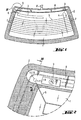
- a fixed transparent window 1 made of glass or plastic is fitted with an opaque edge band peripheral 2 as well as antenna elements 3, 4.
- the antenna elements 3, 4, their connection sections 6 as well as the heating range 5 and its common conductors 7 can be made on the surface of a glass pane by the conventional method of screen printing from a conductive slip and baked when heating the glass for tempering. This surface is, in the assembled state, turned towards the interior side of a cockpit, where most of the edge strip opaque is covered by interior trim.
- the necessary electrical connections from the range of heating 5, respectively of the two common conductors 7, are not described further here. They can be made with conventional individual fittings.
- connection sections mentioned 6 extend over the face of the glass up to the opaque edge strip 2.
- the along the upper edge of the window 1 is also arranged, on the opaque edge strip, a shaped contact element 8 of tape, which covers the ends of the sections of connection 6.
- It serves on the one hand as a flat cable for the electrical connection and connection of elements functional electrics arranged on the glass, on the other hand also for supporting circuit elements 9 such as modules electronics, such as amplifiers, which are not indicated here only schematically in the form of housings.
- circuit elements 9 such as modules electronics, such as amplifiers, which are not indicated here only schematically in the form of housings.
- a 8 'output line Approximately in the middle of the contact element 8 is indicated a 8 'output line, which in a manner known per se understand all the necessary external connections the window with its electrical functional elements.
- the external fittings can, depending on requirements, operate with an electrical, electro-optical or optical transmission of signals.
- the output line 8 ' can be represented as a common conductor, which
- Fig. 2 shows in detail the upper left corner of the window 1.
- the contact element 8 covers the contact face 10.
- One of the circuit elements 9 is located on the contact element 8 in the immediate vicinity of the face contact 10, a conductive path 14 being indicated at broken lines between the contact face 10 and the element of circuit 9. This conductive path passes inside of contact element 8, as will be further discussed, and it ends with the contact face 10.
- Fig. 2 is also indicated, by way of illustration in lines mixed, an extension of the contact element 8 beyond the angle of the fixed pane along its left side edge as well as an electrical conductor embedded in the element of contact, which can be carried out inside this extension.
- it can be, for example, signaling and control conductors as well as distribution conductors for antenna amplifiers active or for heating range 5, respectively for common conductors 7.
- the element of contact 8 forms a bundle of cables for all electrical functional elements, which are provided on the window 1. With an adequate design, it can even replace conventional individual fittings for the range of heating 5.
- FIG. 3 we recognize the vertical structure of the device in the detail area of Fig. 2.
- the base is glass 1, on the edge area of which the opaque edge strip 2 is deposited.
- One of connecting sections 6 comes out of the face of the glass on the edge strip 2 and ends here with the contact face 10.
- a layer of adhesive 11 assembles the contact element 8 totally with the edge band. It spans the face of the contact element, also on the area of the connection section 6, it is however provided with a recess above the contact face 10.
- the contact element 8 consists of the matrix formed from several thin strips of plastic 12, 13 non-conductive.
- the strip 12 forming the underside is provided with an adhesive layer 11.
- Between the strips are embedded in the conductive paths 14 formed of electrically conductive metal strips with appropriate cross sections for the application respective, respectively for electrical power (also known per se as a multilayer conductor).
- the contact face 10 In the area of the contact face 10, it is provided in the lower plastic strip 12 of contact element 8 a recess, which clears one of the conductive paths 14 to this place. It can also end here. In this place, a brazed connection 15 can be made between the conductive path 14 and the contact face 10.
- the conductive path 14 is, for this purpose, provided for this location, where appropriate also the contact face 10 itself, pre-tinning.
- At least the plastic strip 13 of the upper side is made of a material like the polyimide, which can safely withstand the contribution of heat required for brazing the core of the assembly brazed.
- an electrical conductor of link 16 which leads from the conductive path 14 in the module 9.
- a reinforcement insert 17 embedded in the upper plastic strip 13 of the element contact 8 below the housing of the circuit element 9.
- corner area is made with a corner connector separate, as an alternative to the simplified representation of FIG. 2, then the conductive path 14 will end therein and its electrical contact with the contact face 10 is made in the area covered by the corner connector. In this you can use a mechanical junction assembly by plug or push button.
- the contact face 10 forms the socket of the antenna concerned and the brazed assembly 15, the conductive track 14 and the connecting conductor 16 form a short ohmic coupling of the antenna to the circuit element 9 forming an amplifier.
- contact element shown schematically here is a simple form of implementation.
- several track plans may be provided or conductive strips one above the other, in a manner known per se.
Abstract
Description
- Fig. 1
- montre une vitre avec plusieurs éléments fonctionnels électriques et un élément de contact disposé le long du bord supérieur de la vitre; la
- Fig. 2
- représente en détail l'angle supérieur gauche de la vitre de la Figure 1; et la
- Fig. 3
- est une représentation en coupe du détail de la Figure 2.
Claims (16)
- Dispositif de liaison de plusieurs éléments fonctionnels électriques, en particulier d'éléments d'antennes, disposés sur une vitre transparente, en particulier sur une vitre d'automobile, au moyen d'un élément de contact unique et de ses conducteurs de liaison vers des ensembles qui suivent, dans lequel chaque élément fonctionnel est raccordé à au moins une face de contact disposée sur la face de la vitre à proximité du bord et l'élément de contact est composé d'une matrice flexible recouvrant plusieurs faces de contact, d'un certain nombre de conducteurs isolés les uns des autres disposés dans la matrice ainsi que de faces de raccordement des conducteurs disposées suivant la position des faces de contact recouvertes, caractérisé en ce quedes faces de contact (10) à raccorder au moyen d'un élément de contact individuel (8) sont réparties le long du bord de la vitre (1), en particulier dans les zones d'angle de celle-ci; en ce quel'élément de contact (8) a une forme adaptée au bord de la vitre; et en ce quela matrice de l'élément de contact (8) est en outre prévue comme support pour des éléments de circuit (9) disposés à proximité immédiate des faces de contact (10) et reliés électriquement à celles-ci par des conducteurs (14, 16).
- Dispositif de liaison suivant la revendication 1, caractérisé en ce que l'élément de contact (8) s'étend le long d'au moins un côté de la vitre (1) parallèlement au bord de celle-ci.
- Dispositif de liaison suivant la revendication 1 ou 2, caractérisé en ce que l'élément de contact (8) s'étend le long de plusieurs côtés de la vitre (1) parallèlement aux bords de celle-ci.
- Dispositif de liaison suivant l'une quelconque des revendications précédentes, caractérisé en ce que la matrice (12, 13) de l'élément de contact (8) est mécaniquement renforcée dans la région de points de fixation pour des éléments de circuit (9).
- Dispositif de liaison suivant l'une quelconque des revendications précédentes, caractérisé en ce que l'élément de contact (8) est équipé d'une ligne de sortie (8') en vue du raccordement à des ensembles ou à des réseaux qui suivent.
- Dispositif de liaison suivant la revendication 5, caractérisé en ce que la ligne de sortie est un conducteur commun, auquel est associé au moins un adaptateur de signal/décodeur disposé sur l'élément de contact (8) .
- Dispositif de liaison suivant l'une quelconque des revendications précédentes, caractérisé en ce que le côté plat de l'élément de contact (8) tourné vers la vitre (1) est revêtu d'une couche de colle (11), en particulier d'une bande adhésive double face, en vue du collage permanent à la vitre (1).
- Dispositif de liaison suivant l'une quelconque des revendications précédentes, caractérisé en ce que les faces de raccordement de conducteurs de l'élément de contact (8) sont pré-revêtues avec un agent d'assemblage conducteur, en particulier un agent de brasage ou une colle.
- Dispositif de liaison suivant l'une quelconque des revendications précédentes, caractérisé en ce que les faces de raccordement de conducteurs de l'élément de contact peuvent être mises en contact électrique avec les faces de contact de la vitre par des moyens d'assemblage à jonction mécanique.
- Dispositif de liaison suivant l'une quelconque des revendications précédentes, caractérisé en ce que l'élément de contact est pourvu d'accessoires de positionnement pour aider à son montage en position correcte sur la vitre.
- Dispositif de liaison suivant la revendication 10, caractérisé en ce que les accessoires de positionnement sont réalisés sous la forme de butées assemblées à l'élément de contact, à appliquer sur l'arête frontale de la vitre.
- Dispositif de liaison suivant la revendication 11, caractérisé en ce que les butées sont reliées à l'élément de contact par des zones de moindre résistance.
- Dispositif de liaison suivant l'une quelconque des revendications précédentes, caractérisé en ce que l'élément de contact est lui-même un support de structures d'antennes, en particulier de structures d'antennes convenant pour la gamme de fréquences GHz.
- Vitre, en particulier vitre d'automobile (1), avec des éléments fonctionnels électriques et avec un dispositif de liaison de ces éléments fonctionnels suivant l'une quelconque des revendications précédentes.
- Vitre suivant la revendication 14, caractérisée en ce que le dispositif de liaison est fixé sur une face de la vitre tournée vers un espace intérieur à une distance prédéterminée du bord de cette vitre.
- Vitre suivant la revendication 14 ou 15, caractérisée en ce que l'élément de contact (8) est, en plus de ses raccordements aux éléments fonctionnels sur la vitre, disposé sur la face d'un bandeau coloré opaque (2) s'étendant le long du bord de la vitre (1).
Applications Claiming Priority (2)
| Application Number | Priority Date | Filing Date | Title |
|---|---|---|---|
| DE10002777 | 2000-01-22 | ||
| DE10002777A DE10002777C1 (de) | 2000-01-22 | 2000-01-22 | Kontaktierung einer Scheibe mit elektrischen Funktionen |
Publications (3)
| Publication Number | Publication Date |
|---|---|
| EP1119071A2 true EP1119071A2 (fr) | 2001-07-25 |
| EP1119071A3 EP1119071A3 (fr) | 2002-08-21 |
| EP1119071B1 EP1119071B1 (fr) | 2021-02-24 |
Family
ID=7628453
Family Applications (1)
| Application Number | Title | Priority Date | Filing Date |
|---|---|---|---|
| EP01400122.6A Expired - Lifetime EP1119071B1 (fr) | 2000-01-22 | 2001-01-17 | Dispositif de liaison d'une vitre avec des fonctions électriques |
Country Status (5)
| Country | Link |
|---|---|
| US (2) | US6534720B2 (fr) |
| EP (1) | EP1119071B1 (fr) |
| JP (1) | JP2001251119A (fr) |
| KR (1) | KR100798091B1 (fr) |
| DE (1) | DE10002777C1 (fr) |
Cited By (3)
| Publication number | Priority date | Publication date | Assignee | Title |
|---|---|---|---|---|
| FR2921520A1 (fr) * | 2007-09-20 | 2009-03-27 | Saint Gobain | Element de connexion electrique et vitrage pourvu d'un tel element |
| US9155206B2 (en) | 2007-12-11 | 2015-10-06 | Saint-Gobain Glass France | Solder connection element |
| CN110998970A (zh) * | 2017-08-02 | 2020-04-10 | 奥迪股份公司 | 用于车辆的天线装置 |
Families Citing this family (33)
| Publication number | Priority date | Publication date | Assignee | Title |
|---|---|---|---|---|
| DE10129664C2 (de) * | 2001-06-20 | 2003-04-30 | Saint Gobain Sekurit D Gmbh | Antennenscheibe mit einem Hochfrequenzbauteil |
| DE10204257A1 (de) * | 2002-02-02 | 2003-08-07 | Grundig Ag I Ins | Gehäuse für Geräte der Unterhaltungselektronik |
| DE10256643A1 (de) * | 2002-12-03 | 2004-06-17 | Hella Kg Hueck & Co. | Flachleiterfixierung für elektronische, elektromechanische oder elektrooptische Geräte auf Autoscheiben |
| DE10319607B3 (de) | 2003-05-02 | 2004-10-14 | Saint-Gobain Sekurit Deutschland Gmbh & Co. Kg | Korrosionsschutzschaltung für eine Leiterstruktur auf einer Antennenscheibe, Verfahren zum Betreiben einer aktiven Antennenscheibe und Antennenscheibe für Fahrzeuge |
| DE10336972A1 (de) * | 2003-08-12 | 2005-03-10 | Hella Kgaa Hueck & Co | Elektrische Verbindung |
| DE102004017101A1 (de) * | 2003-12-17 | 2005-07-21 | Volkswagen Ag | Diagnostizierbare Befestigungsvorrichtung für Elektronikkomponenten und entsprechendes Diagnoseverfahren |
| JP2005260659A (ja) * | 2004-03-12 | 2005-09-22 | Nippon Sheet Glass Co Ltd | アンテナ付き車両用ウィンドシールド |
| US7134201B2 (en) | 2004-11-12 | 2006-11-14 | Agc Automotive Americas R&D, Inc. | Window pane and a method of bonding a connector to the window pane |
| US7223939B2 (en) * | 2004-11-12 | 2007-05-29 | Agc Automotive Americas, R & D, Inc. | Electrical connector for a window pane of a vehicle |
| DE102005035427A1 (de) * | 2005-07-28 | 2007-02-01 | Webasto Ag | Dachmodul für ein Fahrzeug |
| JP2007069722A (ja) * | 2005-09-06 | 2007-03-22 | Nippon Sheet Glass Co Ltd | 車両用窓ガラスおよび電子タグの取り付け構造 |
| US7612727B2 (en) * | 2005-12-29 | 2009-11-03 | Exatec, Llc | Antenna for plastic window panel |
| KR100765653B1 (ko) * | 2006-07-10 | 2007-10-10 | 현대자동차주식회사 | 자동차용 글래스 안테나 잭 |
| JP4888126B2 (ja) * | 2007-01-12 | 2012-02-29 | マツダ株式会社 | Am/fm受信用アンテナ |
| DE102007003015A1 (de) * | 2007-01-20 | 2008-07-24 | Wilhelm Karmann Gmbh | Anordnung wenigstens eines Halteelements an einer Kunststoffscheibe |
| US20080277177A1 (en) * | 2007-05-09 | 2008-11-13 | Gm Global Technology Operations, Inc. | Wiring System and Method for a Rearview Mirror |
| DE102007059818B3 (de) * | 2007-12-11 | 2009-04-09 | Saint-Gobain Sekurit Deutschland Gmbh & Co. Kg | Fensterscheibe mit einem elektrischen Flachanschlusselement |
| KR100974767B1 (ko) | 2008-04-16 | 2010-08-06 | 현대자동차주식회사 | 차량의 글라스 안테나 |
| US8284104B2 (en) * | 2009-02-13 | 2012-10-09 | Carr William N | Multiple-resonator antenna |
| US8477079B2 (en) * | 2009-02-13 | 2013-07-02 | William N. Carr | Multiple-cavity antenna |
| US8384599B2 (en) * | 2009-02-13 | 2013-02-26 | William N. Carr | Multiple-cavity antenna |
| DE102009030344A1 (de) | 2009-06-25 | 2010-12-30 | Bayerische Motoren Werke Aktiengesellschaft | Fahrzeugscheibe mit mindestens einem Heizleiter und mindestens einer Antenne |
| GB201007346D0 (en) * | 2010-05-04 | 2010-06-16 | Pilkington Group Ltd | Soldering on thin glass sheets |
| DE102011009267A1 (de) * | 2011-01-24 | 2012-07-26 | Valeo Schalter Und Sensoren Gmbh | Sensoranordnung für ein Kraftfahrzeug, Kraftfahrzeug und Verfahren zur Herstellung einer Sensoranordnung |
| US9272371B2 (en) | 2013-05-30 | 2016-03-01 | Agc Automotive Americas R&D, Inc. | Solder joint for an electrical conductor and a window pane including same |
| WO2015082550A1 (fr) * | 2013-12-04 | 2015-06-11 | Hirschmann Car Communication Gmbh | Procédé de réduction de la valeur de l'impédance caractéristique de conducteurs plats flexibles pour la connexion de structures d'antennes sur des vitres de véhicules |
| DE102015115591A1 (de) * | 2015-09-16 | 2017-03-16 | Airbus Ds Optronics Gmbh | Optronische Sensorvorrichtung |
| US10263362B2 (en) | 2017-03-29 | 2019-04-16 | Agc Automotive Americas R&D, Inc. | Fluidically sealed enclosure for window electrical connections |
| US10849192B2 (en) | 2017-04-26 | 2020-11-24 | Agc Automotive Americas R&D, Inc. | Enclosure assembly for window electrical connections |
| US10978777B1 (en) | 2017-09-14 | 2021-04-13 | Apple Inc. | Systems having windows with patterned coatings |
| GB201804622D0 (en) * | 2018-03-22 | 2018-05-09 | Central Glass Co Ltd | Method of producing a vehicle glass assembly |
| CN110562165A (zh) * | 2019-09-11 | 2019-12-13 | 宁波信泰机械有限公司 | 一种可加热雷达罩端部连接结构 |
| GB202002611D0 (en) * | 2020-02-25 | 2020-04-08 | Pilkington Group Ltd | Glazing comprising an antenna and method of manufacturing the same and use of the same |
Citations (3)
| Publication number | Priority date | Publication date | Assignee | Title |
|---|---|---|---|---|
| EP0597757A2 (fr) * | 1992-11-10 | 1994-05-18 | Saint Gobain Vitrage International | Antenne de vitrage pour véhicule automobile |
| EP0645240A1 (fr) * | 1993-09-23 | 1995-03-29 | Saint-Gobain Vitrage International | Procédé de fabrication d'un vitrage en verre feuilleté comportant des fils d'antenne incorporés |
| US5867128A (en) * | 1995-09-28 | 1999-02-02 | Saint Gobain Vitrage | Multicontact for antenna window |
Family Cites Families (24)
| Publication number | Priority date | Publication date | Assignee | Title |
|---|---|---|---|---|
| US3646561A (en) * | 1971-01-19 | 1972-02-29 | Edwin B Clarke | Adhesively secured automobile windshield antenna |
| DE7527621U (de) * | 1975-09-01 | 1976-05-20 | Meinke, Hans Heinrich, Prof. Dr., 8035 Gauting | Antenne fuer den rundfunkempfang im kraftfahrzeug |
| JPS6269704A (ja) * | 1985-09-21 | 1987-03-31 | Nippon Sheet Glass Co Ltd | アンテナ |
| DE3641738A1 (de) * | 1986-12-06 | 1988-06-16 | Flachglas Ag | Kraftfahrzeugscheibe |
| DE3911178A1 (de) * | 1989-04-06 | 1990-10-11 | Lindenmeier Heinz | Scheibenantennensystem mit antennenverstaerker |
| US5363114A (en) | 1990-01-29 | 1994-11-08 | Shoemaker Kevin O | Planar serpentine antennas |
| JPH0810969Y2 (ja) * | 1990-09-18 | 1996-03-29 | 日本板硝子株式会社 | シート状アンテナ |
| US5083135A (en) * | 1990-11-13 | 1992-01-21 | General Motors Corporation | Transparent film antenna for a vehicle window |
| DE4304788C2 (de) * | 1993-02-17 | 1996-05-15 | Ver Glaswerke Gmbh | Verfahren zur Herstellung einer Leiterstruktur mit sich kreuzenden elektrischen Leitern auf der Oberfläche einer Glasscheibe |
| CA2201340C (fr) * | 1994-09-28 | 2005-06-28 | Keith Jeremy Twort | Antenne |
| US5739794A (en) * | 1995-05-22 | 1998-04-14 | General Motors Corporation | Vehicle window antenna with parasitic slot transmission line |
| US5528314A (en) * | 1995-05-22 | 1996-06-18 | General Motors Corporation | Transparent vehicle window antenna |
| US5712645A (en) * | 1995-10-06 | 1998-01-27 | Minnesota Mining And Manufacturing Company | Antenna adapted for placement in the window of a vehicle |
| US5999134A (en) | 1996-12-19 | 1999-12-07 | Ppg Industries Ohio, Inc. | Glass antenna system with an impedance matching network |
| JPH10308620A (ja) * | 1997-05-08 | 1998-11-17 | Harada Ind Co Ltd | Gps波用フィルムアンテナ装置 |
| US5959581A (en) * | 1997-08-28 | 1999-09-28 | General Motors Corporation | Vehicle antenna system |
| US5940042A (en) * | 1997-09-05 | 1999-08-17 | Northrop Grumman Corporation | Windshield slot antenna for vehicle transmissions |
| JPH11301377A (ja) * | 1998-04-24 | 1999-11-02 | Harada Ind Co Ltd | 自動車用受信制御システム |
| DE19823202C2 (de) * | 1998-05-25 | 2003-05-28 | Hirschmann Electronics Gmbh | Fahrzeug-Antenneneinrichtung |
| JP3761015B2 (ja) * | 1998-06-22 | 2006-03-29 | マツダ株式会社 | 車両用ガラスアンテナの補修部材 |
| US6097345A (en) * | 1998-11-03 | 2000-08-01 | The Ohio State University | Dual band antenna for vehicles |
| DE19856663C2 (de) * | 1998-12-09 | 2003-04-03 | Saint Gobain Sekurit D Gmbh | Kontaktvorrichtung für ein an einer Fensterscheibe angeordnetes elektrisches Funktionselement |
| US6266023B1 (en) * | 1999-06-24 | 2001-07-24 | Delphi Technologies, Inc. | Automotive radio frequency antenna system |
| US6118410A (en) * | 1999-07-29 | 2000-09-12 | General Motors Corporation | Automobile roof antenna shelf |
-
2000
- 2000-01-22 DE DE10002777A patent/DE10002777C1/de not_active Expired - Lifetime
-
2001
- 2001-01-17 EP EP01400122.6A patent/EP1119071B1/fr not_active Expired - Lifetime
- 2001-01-17 JP JP2001008549A patent/JP2001251119A/ja active Pending
- 2001-01-19 KR KR1020010003051A patent/KR100798091B1/ko not_active IP Right Cessation
- 2001-01-22 US US09/765,649 patent/US6534720B2/en not_active Expired - Lifetime
-
2002
- 2002-10-18 US US10/273,258 patent/US6576845B2/en not_active Expired - Lifetime
Patent Citations (3)
| Publication number | Priority date | Publication date | Assignee | Title |
|---|---|---|---|---|
| EP0597757A2 (fr) * | 1992-11-10 | 1994-05-18 | Saint Gobain Vitrage International | Antenne de vitrage pour véhicule automobile |
| EP0645240A1 (fr) * | 1993-09-23 | 1995-03-29 | Saint-Gobain Vitrage International | Procédé de fabrication d'un vitrage en verre feuilleté comportant des fils d'antenne incorporés |
| US5867128A (en) * | 1995-09-28 | 1999-02-02 | Saint Gobain Vitrage | Multicontact for antenna window |
Cited By (5)
| Publication number | Priority date | Publication date | Assignee | Title |
|---|---|---|---|---|
| FR2921520A1 (fr) * | 2007-09-20 | 2009-03-27 | Saint Gobain | Element de connexion electrique et vitrage pourvu d'un tel element |
| WO2009040057A1 (fr) * | 2007-09-20 | 2009-04-02 | Saint-Gobain Glass France | Élément de connexion et disque présentant un tel élément de connexion |
| US9155206B2 (en) | 2007-12-11 | 2015-10-06 | Saint-Gobain Glass France | Solder connection element |
| CN110998970A (zh) * | 2017-08-02 | 2020-04-10 | 奥迪股份公司 | 用于车辆的天线装置 |
| CN110998970B (zh) * | 2017-08-02 | 2021-07-27 | 奥迪股份公司 | 用于车辆的天线装置 |
Also Published As
| Publication number | Publication date |
|---|---|
| US6576845B2 (en) | 2003-06-10 |
| EP1119071B1 (fr) | 2021-02-24 |
| KR20010076363A (ko) | 2001-08-11 |
| US20030058178A1 (en) | 2003-03-27 |
| DE10002777C1 (de) | 2001-08-09 |
| US20030034172A1 (en) | 2003-02-20 |
| EP1119071A3 (fr) | 2002-08-21 |
| US6534720B2 (en) | 2003-03-18 |
| JP2001251119A (ja) | 2001-09-14 |
| KR100798091B1 (ko) | 2008-01-28 |
Similar Documents
| Publication | Publication Date | Title |
|---|---|---|
| EP1119071B1 (fr) | Dispositif de liaison d'une vitre avec des fonctions électriques | |
| EP0766338B1 (fr) | Multicontact pour vitrage antenne | |
| EP3408089B1 (fr) | Vitrage feuillete de vehicule avec ecran amoled | |
| EP1623480B1 (fr) | Antenne de vitrage d'automobiles | |
| EP0608180B1 (fr) | Procédé de fabrication d'un vitrage antenne et vitrage antenne | |
| KR101782333B1 (ko) | 전기 가열 윈도우 | |
| EP0975045A1 (fr) | Vitrage à antenne pour véhicules automobiles | |
| WO2003009415A1 (fr) | Antenne de vitre avec un composant a haute frequence | |
| CN100531477C (zh) | 具有用于钎焊连接的非透明接触表面的透明窗玻璃 | |
| JP5320459B2 (ja) | 保持ソケット付き車両用窓ガラス | |
| EP0597757B1 (fr) | Antenne de vitrage pour véhicule automobile | |
| US11001038B2 (en) | Laminated assembly | |
| EP0800333A2 (fr) | Pare-brise pouvant être chauffé électriquement | |
| US20230402743A1 (en) | Antenna assembly, antenna system, and vehicle | |
| FR2762719A1 (fr) | Faisceau de lignes de cablage pour un vehicule automobile | |
| EP3117481B1 (fr) | Module d'antenne de véhicule automobile | |
| EP1399975B1 (fr) | Capteur de luminosite et son procede de fabrication | |
| FR2866156A1 (fr) | Antenne serigraphiee pour lunette arriere et lunette de custode de vehicule automobile de type break. | |
| FR2646968A1 (fr) | Dispositif de connexion pour circuit de chauffage et de desembuage d'une glace | |
| CN113226727A (zh) | 玻璃质玻璃板 |
Legal Events
| Date | Code | Title | Description |
|---|---|---|---|
| PUAI | Public reference made under article 153(3) epc to a published international application that has entered the european phase |
Free format text: ORIGINAL CODE: 0009012 |
|
| AK | Designated contracting states |
Kind code of ref document: A2 Designated state(s): AT BE CH CY DE DK ES FI FR GB GR IE IT LI LU MC NL PT SE TR |
|
| AX | Request for extension of the european patent |
Free format text: AL;LT;LV;MK;RO;SI |
|
| PUAL | Search report despatched |
Free format text: ORIGINAL CODE: 0009013 |
|
| AK | Designated contracting states |
Kind code of ref document: A3 Designated state(s): AT BE CH CY DE DK ES FI FR GB GR IE IT LI LU MC NL PT SE TR |
|
| AX | Request for extension of the european patent |
Free format text: AL;LT;LV;MK;RO;SI |
|
| 17P | Request for examination filed |
Effective date: 20030201 |
|
| AKX | Designation fees paid |
Designated state(s): AT BE CH CY DE DK ES FI FR GB GR IE IT LI LU MC NL PT SE TR |
|
| 17Q | First examination report despatched |
Effective date: 20070703 |
|
| STAA | Information on the status of an ep patent application or granted ep patent |
Free format text: STATUS: EXAMINATION IS IN PROGRESS |
|
| GRAP | Despatch of communication of intention to grant a patent |
Free format text: ORIGINAL CODE: EPIDOSNIGR1 |
|
| STAA | Information on the status of an ep patent application or granted ep patent |
Free format text: STATUS: GRANT OF PATENT IS INTENDED |
|
| INTG | Intention to grant announced |
Effective date: 20181128 |
|
| RIC1 | Information provided on ipc code assigned before grant |
Ipc: H01Q 1/12 20060101AFI20010411BHEP |
|
| GRAJ | Information related to disapproval of communication of intention to grant by the applicant or resumption of examination proceedings by the epo deleted |
Free format text: ORIGINAL CODE: EPIDOSDIGR1 |
|
| STAA | Information on the status of an ep patent application or granted ep patent |
Free format text: STATUS: EXAMINATION IS IN PROGRESS |
|
| INTC | Intention to grant announced (deleted) | ||
| RAP1 | Party data changed (applicant data changed or rights of an application transferred) |
Owner name: SAINT-GOBAIN GLASS FRANCE |
|
| GRAP | Despatch of communication of intention to grant a patent |
Free format text: ORIGINAL CODE: EPIDOSNIGR1 |
|
| STAA | Information on the status of an ep patent application or granted ep patent |
Free format text: STATUS: GRANT OF PATENT IS INTENDED |
|
| INTG | Intention to grant announced |
Effective date: 20200925 |
|
| GRAS | Grant fee paid |
Free format text: ORIGINAL CODE: EPIDOSNIGR3 |
|
| REG | Reference to a national code |
Ref country code: DE Ref legal event code: R071 Ref document number: 60151318 Country of ref document: DE |
|
| GRAA | (expected) grant |
Free format text: ORIGINAL CODE: 0009210 |
|
| STAA | Information on the status of an ep patent application or granted ep patent |
Free format text: STATUS: THE PATENT HAS BEEN GRANTED |
|
| AK | Designated contracting states |
Kind code of ref document: B1 Designated state(s): AT BE CH CY DE DK ES FI FR GB GR IE IT LI LU MC NL PT SE TR |
|
| REG | Reference to a national code |
Ref country code: GB Ref legal event code: FG4D Free format text: NOT ENGLISH |
|
| REG | Reference to a national code |
Ref country code: CH Ref legal event code: EP |
|
| REG | Reference to a national code |
Ref country code: NL Ref legal event code: MK Effective date: 20210116 |
|
| REG | Reference to a national code |
Ref country code: DE Ref legal event code: R096 Ref document number: 60151318 Country of ref document: DE |
|
| REG | Reference to a national code |
Ref country code: CH Ref legal event code: PL Ref country code: AT Ref legal event code: REF Ref document number: 1365637 Country of ref document: AT Kind code of ref document: T Effective date: 20210315 |
|
| REG | Reference to a national code |
Ref country code: IE Ref legal event code: FG4D Free format text: LANGUAGE OF EP DOCUMENT: FRENCH |
|
| REG | Reference to a national code |
Ref country code: IE Ref legal event code: MK9A |
|
| REG | Reference to a national code |
Ref country code: GB Ref legal event code: PE20 Expiry date: 20210116 |
|
| REG | Reference to a national code |
Ref country code: BE Ref legal event code: MK Effective date: 20210117 |
|
| PG25 | Lapsed in a contracting state [announced via postgrant information from national office to epo] |
Ref country code: GB Free format text: LAPSE BECAUSE OF EXPIRATION OF PROTECTION Effective date: 20210116 |
|
| PG25 | Lapsed in a contracting state [announced via postgrant information from national office to epo] |
Ref country code: GR Free format text: LAPSE BECAUSE OF FAILURE TO SUBMIT A TRANSLATION OF THE DESCRIPTION OR TO PAY THE FEE WITHIN THE PRESCRIBED TIME-LIMIT Effective date: 20210525 Ref country code: PT Free format text: LAPSE BECAUSE OF FAILURE TO SUBMIT A TRANSLATION OF THE DESCRIPTION OR TO PAY THE FEE WITHIN THE PRESCRIBED TIME-LIMIT Effective date: 20210624 |
|
| REG | Reference to a national code |
Ref country code: AT Ref legal event code: MK05 Ref document number: 1365637 Country of ref document: AT Kind code of ref document: T Effective date: 20210224 |
|
| PG25 | Lapsed in a contracting state [announced via postgrant information from national office to epo] |
Ref country code: SE Free format text: LAPSE BECAUSE OF FAILURE TO SUBMIT A TRANSLATION OF THE DESCRIPTION OR TO PAY THE FEE WITHIN THE PRESCRIBED TIME-LIMIT Effective date: 20210224 |
|
| PG25 | Lapsed in a contracting state [announced via postgrant information from national office to epo] |
Ref country code: AT Free format text: LAPSE BECAUSE OF FAILURE TO SUBMIT A TRANSLATION OF THE DESCRIPTION OR TO PAY THE FEE WITHIN THE PRESCRIBED TIME-LIMIT Effective date: 20210224 |
|
| REG | Reference to a national code |
Ref country code: DE Ref legal event code: R097 Ref document number: 60151318 Country of ref document: DE |
|
| PG25 | Lapsed in a contracting state [announced via postgrant information from national office to epo] |
Ref country code: ES Free format text: LAPSE BECAUSE OF FAILURE TO SUBMIT A TRANSLATION OF THE DESCRIPTION OR TO PAY THE FEE WITHIN THE PRESCRIBED TIME-LIMIT Effective date: 20210224 Ref country code: DK Free format text: LAPSE BECAUSE OF FAILURE TO SUBMIT A TRANSLATION OF THE DESCRIPTION OR TO PAY THE FEE WITHIN THE PRESCRIBED TIME-LIMIT Effective date: 20210224 |
|
| PLBE | No opposition filed within time limit |
Free format text: ORIGINAL CODE: 0009261 |
|
| STAA | Information on the status of an ep patent application or granted ep patent |
Free format text: STATUS: NO OPPOSITION FILED WITHIN TIME LIMIT |
|
| 26N | No opposition filed |
Effective date: 20211125 |
|
| PG25 | Lapsed in a contracting state [announced via postgrant information from national office to epo] |
Ref country code: IT Free format text: LAPSE BECAUSE OF FAILURE TO SUBMIT A TRANSLATION OF THE DESCRIPTION OR TO PAY THE FEE WITHIN THE PRESCRIBED TIME-LIMIT Effective date: 20210224 |