EP0597757B1 - Antenne de vitrage pour véhicule automobile - Google Patents
Antenne de vitrage pour véhicule automobile Download PDFInfo
- Publication number
- EP0597757B1 EP0597757B1 EP93402701A EP93402701A EP0597757B1 EP 0597757 B1 EP0597757 B1 EP 0597757B1 EP 93402701 A EP93402701 A EP 93402701A EP 93402701 A EP93402701 A EP 93402701A EP 0597757 B1 EP0597757 B1 EP 0597757B1
- Authority
- EP
- European Patent Office
- Prior art keywords
- antenna
- glazing
- conductor
- conductive surface
- coaxial cable
- Prior art date
- Legal status (The legal status is an assumption and is not a legal conclusion. Google has not performed a legal analysis and makes no representation as to the accuracy of the status listed.)
- Expired - Lifetime
Links
Images

Classifications
-
- B—PERFORMING OPERATIONS; TRANSPORTING
- B32—LAYERED PRODUCTS
- B32B—LAYERED PRODUCTS, i.e. PRODUCTS BUILT-UP OF STRATA OF FLAT OR NON-FLAT, e.g. CELLULAR OR HONEYCOMB, FORM
- B32B17/00—Layered products essentially comprising sheet glass, or glass, slag, or like fibres
- B32B17/06—Layered products essentially comprising sheet glass, or glass, slag, or like fibres comprising glass as the main or only constituent of a layer, next to another layer of a specific material
- B32B17/10—Layered products essentially comprising sheet glass, or glass, slag, or like fibres comprising glass as the main or only constituent of a layer, next to another layer of a specific material of synthetic resin
- B32B17/10005—Layered products essentially comprising sheet glass, or glass, slag, or like fibres comprising glass as the main or only constituent of a layer, next to another layer of a specific material of synthetic resin laminated safety glass or glazing
- B32B17/10009—Layered products essentially comprising sheet glass, or glass, slag, or like fibres comprising glass as the main or only constituent of a layer, next to another layer of a specific material of synthetic resin laminated safety glass or glazing characterized by the number, the constitution or treatment of glass sheets
- B32B17/10036—Layered products essentially comprising sheet glass, or glass, slag, or like fibres comprising glass as the main or only constituent of a layer, next to another layer of a specific material of synthetic resin laminated safety glass or glazing characterized by the number, the constitution or treatment of glass sheets comprising two outer glass sheets
-
- H—ELECTRICITY
- H01—ELECTRIC ELEMENTS
- H01Q—ANTENNAS, i.e. RADIO AERIALS
- H01Q1/00—Details of, or arrangements associated with, antennas
- H01Q1/12—Supports; Mounting means
- H01Q1/1271—Supports; Mounting means for mounting on windscreens
Definitions
- the present invention relates to an antenna glazing for motor vehicles, in which, on the automotive glass surface or inside it, is installed an antenna conductor whose base antenna, connected to the central conductor of a cable coaxial, is arranged in the vicinity of a conductive surface provided in the marginal region of the glazing and connected to the outer conductor of the coaxial cable.
- Antenna structures of this type are suitable, in particular, as transmitting antennas for radio, in particular particular, as an antenna for communications radiotelephones in the digital network. So that the transmission power radiates from the antenna, that such antennas are precisely tuned. For this purpose, they need a defined reference plane to which all electrical parameters are related. AT title of reference plane, a conductive layer of strip-shaped electricity is therefore applied directly on the marginal region of the glazing.
- an antenna structure of this type is known from WO 88/09569.
- the antenna conductor which is provided as a radio antenna preferably for the frequency range between 890 and 960 MHz, the antenna conductor consists of a conductor straight with a free end extending to from the edge of the glazing in the field of vision of this glazing.
- the antenna conductor and the conductive surface serving as a reference plane can be applied by printed and cooked, like the heating conductors of heated glazing, on the glass surface facing the interior of the vehicle interior.
- the resonant frequency depends in a some measure of glazing materials and tolerances geometric when mounting this glazing. Therefore, in the case of these known antennas, it is, moreover, also necessary to reconnect after mounting, if their effectiveness is below an optimal value.
- the object of the invention is to produce an antenna for glazing of the specified type in which the dependence of the resonant frequency with respect to the materials used as well as geometric and mechanical tolerances of the glazing and window frame of the vehicle body is significantly reduced.
- the antenna conductor has the shape of an open loop and is connected at its end, opposite the antenna base, to the conductive surface, and by the fact that the antenna conductor and the conductive surface, are arranged in parallel planes on the glazing and consist of an electrically conductive baking ink.
- Figs. 1 and 2 illustrate glazing monolithic 1 which has been thermally quenched, which is used as rear window and which is provided with a network of heating conductors.
- the conductor network conductors includes a row of heating conductors 2 which extend over the entire width of the glazing, as well as two omnibus conductors 3, 4 arranged laterally at glazing edges.
- the heating conductors 2 and the omnibus conductors 3, 4 are made of baking ink conductive of electricity, qualified as conductive silver, which is applied by screen printing on the glass surface and which is baked in the glass surface during the bending and / or quenching process.
- an antenna structure suitable for radiocommunications at a frequency located in the 900 MHz range is provided with an antenna structure suitable for radiocommunications at a frequency located in the 900 MHz range.
- This antenna structure is made of the same material as the heating conductors 2 and the bus bars 3 and 4 and is printed on the surface of the glass during the same printing operation as these, then also baked at the bending or quenching.
- the antenna structure consists of the conductor antenna 6 in the form of a loop about 0.5 mm wide with an antenna base 7 having the shape of a surface to which the central conductor of the supply cable in the form of a coaxial cable.
- the length L of the conductor loop is, for example, 120 mm while the width B of this loop, i.e.
- the driver loop antenna 6 is, in the case shown, arranged in an upper corner area of the glazing 1 and forms an angle of about 45 ° with the horizontal, but it goes of course it can be installed in any other location of the glazing and be oriented essentially under any angle to the horizontal.
- the antenna conductor 6 is, preferably oriented at right angles to the horizontal.
- the electric counterweight to the antenna conductor 6 in the form of a folded single-pole antenna is formed by the conductive surface 8 which also consists of the same electrically conductive baking ink as the heating conductor 2 and antenna conductor 6, and which was also applied to the glass surface during of the same process step as the other structures conductive.
- the conductive surface 8 is formed of strips 1 to 3 cm wide along the edge of the glazing. The length 1 of this strip-shaped surface 8 is not critical, but should advantageously reach at least 120 mm approximately. In the middle approximately, the conductive surface 8 has a flat projection 9 oriented towards the surface of the glazing which, at its end, forms an annular surface 10.
- the annular surface 10 is provided with a slot 11 radially oriented in which the conductor is arranged antenna 6 whose antenna base 7 is located inside the annular surface 10 concentrically with this one.
- the end zone 6 'of the antenna conductor in form of loop 6 is connected to the flat projection 9 of the conductive surface 8.
- the network of heating conductors and the antenna conductor structure are located on the face glazing facing the interior of the passenger compartment.
- the conductive surface 8 is connected over an area extended to the adhesive bead and, by through the adhesive bead, to the fixing flange metal of the automobile body. Since the currently used adhesive materials have a certain electrical conductivity, the conductive surface 8 is in this way electrically connected to the body. In this way, the antenna is connected directly to the body.
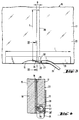
- glass glazing laminated 15 is shown with a wire antenna metal designed according to the invention.
- the glazing in laminated glass 15 consists of the glass sheet individual 16 facing outwards, in assembled condition, of the individual glass sheet 17 facing the interior of the passenger compartment and the middle layer thermoplastic 18 connecting the two glass sheets individual 16 and 17 to each other.
- the glass sheet individual interior 17 is provided on board lower, with a notch 19.
- thermoplastic 18 is a metal wire 20 in the form loop, i.e. in the form of a unipolar antenna folded whose two ends stand out in the area of the marginal notch 19.
- the length L of the wire loop 20 is again a function of the transmission frequency and reaches, for example, again 120 mm while the width B of the wire loop 20 is again about 10 mm.
- a electrically conductive surface in the form of a strip 23 is arranged along the lower edge of the glazing, on the free surface 22 of the laminated glass.
- a electrically conductive surface in the form of a strip 23.
- it may be, for example, a layer of ink or baking ink both conductive of electricity.
- the conductive surface 23 of electricity is however advantageously made of foil sheet which is stuck firmly and permanently on the surface 23 of the glass.
- the surface dimensions of the electrically conductive surface 23 are again not critical, but the length of the foil sheet should be at least about 120mm.
- the antenna is, of course, installed on the edge glass, but it can obviously be installed anywhere else on the glazing Laminated glass. It turned out that results particularly good can be obtained when the antenna is installed in the upper marginal area of the glazing in laminated glass.
- the marginal notch 19 is disposed at the end of an antenna supply cable 25 having the shape of a coaxial cable.
- the first end of the conductor loop 20, that is to say the base of the antenna, is connected to the central conductor 26 of the coaxial cable and the other end 20 'is connected to the external conductor 27 of the coaxial cable 25 and to the conductive surface 23.
- foil strip 28 is connected by soldering on the one hand to the sheet of foil 23 and on the other hand to the outer conductor 27 of the coaxial cable 25.
- the marginal notch 19 is then filled with a suitable hardening polymer and is sealed to protect the connection area and fix the coaxial cable 25 in the glazing.
- the electrically conductive surface 23 is, again, connected over a large area, conductively electricity, through the adhesive bead to the metal frame of the bodywork, so that the antenna receives a well-defined reference potential.
Description
Claims (6)
- Antenne de vitrage pour véhicules automobiles, dans laquelle, sur la surface d'un vitrage automobile (1) ou à l'intérieur de celui-ci est installé un conducteur d'antenne (6, 20) dont la base d'antenne (7), connectée au conducteur central (26) d'un câble coaxial, est disposée au voisinage d'une surface conductrice (8) prévue dans la région marginale du vitrage (1) et connectée au conducteur extérieur (27) du câble coaxial, le conducteur d'antenne (6, 20) ayant la forme d'une boucle ouverte et étant connecté à son extrémité (6', 20'), opposée à la base d'antenne (7), à la surface conductrice (8, 23), caractérisée en ce que le conducteur d'antenne (6, 20) et la surface conductrice (8, 23) sont disposés dans des plans parallèles sur le vitrage (1) et le conducteur d'antenne (6, 20) et la surface conductrice (8, 23) ou le conducteur d'antenne seulement (6, 20) sont constitués d'une encre à cuire conductrice de l'électricité.
- Antenne de vitrage suivant la revendication 1, caractérisée en ce que la base (7) du conducteur d'antenne (6) est disposée à l'intérieur d'un segment superficiel annulaire (10) de la surface conductrice (8) et le conducteur d'antenne (6) connecté à la base d'antenne (7) sort du segment superficiel annulaire (10) à travers une fente (11).
- Antenne de vitrage suivant la revendication 1, caractérisée en ce que dans le cas d'un vitrage en verre feuilleté (15), le conducteur d'antenne a la forme d'une boucle de fil métallique (20) disposée dans la couche intermédiaire thermoplastique (18), et la surface conductrice (23) est disposée dans la zone marginale du vitrage en verre feuilleté sur la surface libre (22) tournée vers l'intérieur de l'habitacle.
- Antenne de vitrage suivant la revendication 3, caractérisée en ce que la surface conductrice (23) est faite d'une feuille de clinquant collée à la surface (22) du vitrage.
- Antenne de vitrage suivant la revendication 3 ou 4, caractérisée en ce qu' à l'antenne est connecté un câble d'amenée d'antenne (25) ayant la forme d'un câble coaxial, le conducteur central (26) du câble coaxial étant connecté à la première extrémité du conducteur d'antenne (20) et le conducteur extérieur (27) du câble coaxial étant conecté d'une part à l'autre extrémité (20') du conducteur d'antenne (20) et d'autre part, par l'intermédiaire d'une bande de clinquant (28), à la surface conductrice (23).
- Antenne de vitrage suivant l'une quelconque des revendications 1 à 5, caractérisée en ce que dans l'état monté, la surface conductrice (8, 23) est reliée par l'intermédiaire d'une couche d'adhésif fixant le vitrage dans la baie de fenêtre, sur une zone étendue, au cadre de fenêtre métallique de la carrosserie du véhicule.
Applications Claiming Priority (2)
| Application Number | Priority Date | Filing Date | Title |
|---|---|---|---|
| DE4237818A DE4237818C3 (de) | 1992-11-10 | 1992-11-10 | Scheibenantenne für Kraftfahrzeuge |
| DE4237818 | 1992-11-10 |
Publications (3)
| Publication Number | Publication Date |
|---|---|
| EP0597757A2 EP0597757A2 (fr) | 1994-05-18 |
| EP0597757A3 EP0597757A3 (fr) | 1995-02-01 |
| EP0597757B1 true EP0597757B1 (fr) | 2000-04-12 |
Family
ID=6472456
Family Applications (1)
| Application Number | Title | Priority Date | Filing Date |
|---|---|---|---|
| EP93402701A Expired - Lifetime EP0597757B1 (fr) | 1992-11-10 | 1993-11-04 | Antenne de vitrage pour véhicule automobile |
Country Status (7)
| Country | Link |
|---|---|
| US (1) | US6198447B1 (fr) |
| EP (1) | EP0597757B1 (fr) |
| JP (1) | JPH06199184A (fr) |
| AT (1) | ATE191816T1 (fr) |
| DE (2) | DE4237818C3 (fr) |
| ES (1) | ES2146604T3 (fr) |
| PT (1) | PT597757E (fr) |
Families Citing this family (13)
| Publication number | Priority date | Publication date | Assignee | Title |
|---|---|---|---|---|
| US5986612A (en) * | 1996-12-30 | 1999-11-16 | General Motors Corporation | Vehicle window antenna |
| DE10002777C1 (de) * | 2000-01-22 | 2001-08-09 | Saint Gobain Sekurit D Gmbh | Kontaktierung einer Scheibe mit elektrischen Funktionen |
| US6317090B1 (en) * | 2000-08-03 | 2001-11-13 | General Motors Corporation | AM/FM solar-ray antenna with mirror wiring grounding strap |
| US6768467B2 (en) | 2002-03-04 | 2004-07-27 | Mia-Com Inc. | Method of RF grounding glass mounted antennas to automotive metal frames |
| US7154444B2 (en) * | 2003-04-04 | 2006-12-26 | General Motors Corporation | Ground plane compensation for mobile antennas |
| DE10319606B4 (de) * | 2003-05-02 | 2005-07-14 | Saint-Gobain Sekurit Deutschland Gmbh & Co. Kg | Antennenscheibe für Fahrzeuge |
| JP4064978B2 (ja) * | 2004-05-28 | 2008-03-19 | 株式会社デンソー | 車載アンテナの搭載構造 |
| US7446719B2 (en) * | 2004-05-28 | 2008-11-04 | Denso Corporation | Mobile antenna mounted on a vehicle body |
| DE102005039914A1 (de) | 2005-08-24 | 2007-03-08 | Robert Bosch Gmbh | Mehrbereichs-Antennenanordnung |
| JP2007081554A (ja) * | 2005-09-12 | 2007-03-29 | Fujitsu Ltd | ガラスアンテナ及びその製造方法 |
| DE202007012124U1 (de) * | 2007-08-30 | 2007-12-13 | Arvinmeritor Gmbh | Verbundbauteil, insbesondere Fahrzeugdachpaneel |
| DE102009030344A1 (de) * | 2009-06-25 | 2010-12-30 | Bayerische Motoren Werke Aktiengesellschaft | Fahrzeugscheibe mit mindestens einem Heizleiter und mindestens einer Antenne |
| WO2013091961A1 (fr) | 2011-12-20 | 2013-06-27 | Saint-Gobain Glass France | Vitre composite pourvue d'une structure d'antenne et d'un bouton de commande intégré |
Family Cites Families (11)
| Publication number | Priority date | Publication date | Assignee | Title |
|---|---|---|---|---|
| US3599214A (en) * | 1969-03-10 | 1971-08-10 | New Tronics Corp | Automobile windshield antenna |
| DE2136759C2 (de) * | 1971-07-22 | 1982-09-30 | Gerhard Prof. Dr.-Ing. 8012 Ottobrunn Flachenecker | Antenne mit metallischem Rahmen und den Rahmen erregendem Unipol |
| US3971030A (en) * | 1972-01-14 | 1976-07-20 | Saint-Gobain Industries | Antenna window |
| CA1034252A (fr) * | 1973-09-26 | 1978-07-04 | Ppg Industries, Inc. | Pare-brise a entenne incorporee |
| DE3630519A1 (de) * | 1986-09-08 | 1988-03-10 | Lindenmeier Heinz | Fensterscheibenantenne parallel zum fensterrahmen |
| GB8711995D0 (en) * | 1987-05-21 | 1987-06-24 | Bsh Electronics Ltd | Vehicle antenna |
| US5293174A (en) * | 1987-05-21 | 1994-03-08 | Kropielnicki Jerzy J | Vehicle antenna |
| US5220336A (en) * | 1990-02-28 | 1993-06-15 | Central Glass Company, Limited | Vehicle window glass antenna for transmission and reception of ultrashort waves |
| US5285210A (en) * | 1990-05-08 | 1994-02-08 | Nippon Sheet Glass Co., Ltd. | Double loop antenna with reactance elements |
| GB9103737D0 (en) * | 1991-02-22 | 1991-04-10 | Pilkington Plc | Antenna for vehicle window |
| DE4125999C1 (en) * | 1991-08-06 | 1992-10-29 | Flachglas Ag, 8510 Fuerth, De | Antenna signal coupler for motor vehicle window - consists of capacitor plates on either side of pane to supply mobile radio appts. e.g. CB or telephone |
-
1992
- 1992-11-10 DE DE4237818A patent/DE4237818C3/de not_active Expired - Fee Related
-
1993
- 1993-11-04 ES ES93402701T patent/ES2146604T3/es not_active Expired - Lifetime
- 1993-11-04 PT PT93402701T patent/PT597757E/pt unknown
- 1993-11-04 DE DE69328339T patent/DE69328339T2/de not_active Expired - Fee Related
- 1993-11-04 AT AT93402701T patent/ATE191816T1/de not_active IP Right Cessation
- 1993-11-04 EP EP93402701A patent/EP0597757B1/fr not_active Expired - Lifetime
- 1993-11-05 US US08/147,485 patent/US6198447B1/en not_active Expired - Fee Related
- 1993-11-05 JP JP5276528A patent/JPH06199184A/ja active Pending
Also Published As
| Publication number | Publication date |
|---|---|
| DE69328339T2 (de) | 2000-12-14 |
| DE4237818A1 (de) | 1994-05-19 |
| EP0597757A2 (fr) | 1994-05-18 |
| DE4237818C2 (de) | 1995-08-31 |
| ATE191816T1 (de) | 2000-04-15 |
| ES2146604T3 (es) | 2000-08-16 |
| PT597757E (pt) | 2000-09-29 |
| EP0597757A3 (fr) | 1995-02-01 |
| DE4237818C3 (de) | 2000-12-14 |
| US6198447B1 (en) | 2001-03-06 |
| DE69328339D1 (de) | 2000-05-18 |
| JPH06199184A (ja) | 1994-07-19 |
Similar Documents
| Publication | Publication Date | Title |
|---|---|---|
| EP0597757B1 (fr) | Antenne de vitrage pour véhicule automobile | |
| EP1119071B1 (fr) | Dispositif de liaison d'une vitre avec des fonctions électriques | |
| EP0975045A1 (fr) | Vitrage à antenne pour véhicules automobiles | |
| EP2649675B1 (fr) | Ensemble fenêtre ayant une couche transparente avec une fente pour un élément d'antenne filaire | |
| EP0766338B1 (fr) | Multicontact pour vitrage antenne | |
| WO2004100311A1 (fr) | Antenne de vitrage d’automobiles | |
| US9293813B2 (en) | Window assembly with transparent regions having a performance enhancing slit formed therein | |
| CA2164366C (fr) | Connecteur electrique | |
| CA2469708A1 (fr) | Vitre chauffante avec un revetement superficiel electriquement conducteur | |
| US5610618A (en) | Motor vehicle antenna systems | |
| FR2571179A1 (fr) | Unite d'antenne mobile | |
| WO2007110544A2 (fr) | Substrat muni d'un element electroconducteur a fonction d'antenne | |
| FR2621742A1 (fr) | Antenne pour vehicule | |
| FR2590728A1 (fr) | Antenne de vitre de vehicule | |
| WO2003009415A1 (fr) | Antenne de vitre avec un composant a haute frequence | |
| EP0800333A2 (fr) | Pare-brise pouvant être chauffé électriquement | |
| GB2157633A (en) | Rear view mirrors | |
| US20230402743A1 (en) | Antenna assembly, antenna system, and vehicle | |
| EP0675576B1 (fr) | Ruban de liaison électrique pour contacteur tournant, en particulier pour véhicules automobiles | |
| EP0325510A2 (fr) | Système d'antennes pour véhicule | |
| FR2737075A1 (fr) | Vitrage automobile a chauffage electrique | |
| EA046386B1 (ru) | Остекление транспортного средства с антенной | |
| EP1926148B1 (fr) | Procédé de fabrication pour un capteur d'image | |
| EP0613205A1 (fr) | Vitre dans laquelle est incorporé un montage radioélectrique et véhicule comportant une telle vitre | |
| EP1107353A1 (fr) | Véhicule automobile avec système d'accès sélectif du type "mains libres" |
Legal Events
| Date | Code | Title | Description |
|---|---|---|---|
| PUAI | Public reference made under article 153(3) epc to a published international application that has entered the european phase |
Free format text: ORIGINAL CODE: 0009012 |
|
| AK | Designated contracting states |
Kind code of ref document: A2 Designated state(s): AT BE DE ES FR GB IT LU NL PT SE |
|
| PUAL | Search report despatched |
Free format text: ORIGINAL CODE: 0009013 |
|
| AK | Designated contracting states |
Kind code of ref document: A3 Designated state(s): AT BE DE ES FR GB IT LU NL PT SE |
|
| 17P | Request for examination filed |
Effective date: 19950315 |
|
| 17Q | First examination report despatched |
Effective date: 19961129 |
|
| GRAG | Despatch of communication of intention to grant |
Free format text: ORIGINAL CODE: EPIDOS AGRA |
|
| RAP1 | Party data changed (applicant data changed or rights of an application transferred) |
Owner name: SEKURIT SAINT GOBAIN DEUTSCHLAND GMBH & CO. KG Owner name: SAINT GOBAIN VITRAGE INTERNATIONAL |
|
| GRAG | Despatch of communication of intention to grant |
Free format text: ORIGINAL CODE: EPIDOS AGRA |
|
| GRAG | Despatch of communication of intention to grant |
Free format text: ORIGINAL CODE: EPIDOS AGRA |
|
| GRAH | Despatch of communication of intention to grant a patent |
Free format text: ORIGINAL CODE: EPIDOS IGRA |
|
| RAP1 | Party data changed (applicant data changed or rights of an application transferred) |
Owner name: SEKURIT SAINT GOBAIN DEUTSCHLAND GMBH & CO. KG Owner name: SAINT-GOBAIN VITRAGE |
|
| GRAH | Despatch of communication of intention to grant a patent |
Free format text: ORIGINAL CODE: EPIDOS IGRA |
|
| GRAA | (expected) grant |
Free format text: ORIGINAL CODE: 0009210 |
|
| AK | Designated contracting states |
Kind code of ref document: B1 Designated state(s): AT BE DE ES FR GB IT LU NL PT SE |
|
| REF | Corresponds to: |
Ref document number: 191816 Country of ref document: AT Date of ref document: 20000415 Kind code of ref document: T |
|
| REF | Corresponds to: |
Ref document number: 69328339 Country of ref document: DE Date of ref document: 20000518 |
|
| ITF | It: translation for a ep patent filed |
Owner name: RACHELI & C. S.R.L. |
|
| GBT | Gb: translation of ep patent filed (gb section 77(6)(a)/1977) |
Effective date: 20000623 |
|
| REG | Reference to a national code |
Ref country code: ES Ref legal event code: FG2A Ref document number: 2146604 Country of ref document: ES Kind code of ref document: T3 |
|
| REG | Reference to a national code |
Ref country code: PT Ref legal event code: SC4A Free format text: AVAILABILITY OF NATIONAL TRANSLATION Effective date: 20000705 |
|
| PLBE | No opposition filed within time limit |
Free format text: ORIGINAL CODE: 0009261 |
|
| STAA | Information on the status of an ep patent application or granted ep patent |
Free format text: STATUS: NO OPPOSITION FILED WITHIN TIME LIMIT |
|
| 26N | No opposition filed | ||
| REG | Reference to a national code |
Ref country code: GB Ref legal event code: IF02 |
|
| PGFP | Annual fee paid to national office [announced via postgrant information from national office to epo] |
Ref country code: PT Payment date: 20061031 Year of fee payment: 14 |
|
| PGFP | Annual fee paid to national office [announced via postgrant information from national office to epo] |
Ref country code: GB Payment date: 20061101 Year of fee payment: 14 |
|
| PGFP | Annual fee paid to national office [announced via postgrant information from national office to epo] |
Ref country code: DE Payment date: 20061102 Year of fee payment: 14 |
|
| PGFP | Annual fee paid to national office [announced via postgrant information from national office to epo] |
Ref country code: NL Payment date: 20061105 Year of fee payment: 14 |
|
| PGFP | Annual fee paid to national office [announced via postgrant information from national office to epo] |
Ref country code: SE Payment date: 20061106 Year of fee payment: 14 |
|
| PGFP | Annual fee paid to national office [announced via postgrant information from national office to epo] |
Ref country code: FR Payment date: 20061107 Year of fee payment: 14 |
|
| PGFP | Annual fee paid to national office [announced via postgrant information from national office to epo] |
Ref country code: LU Payment date: 20061113 Year of fee payment: 14 Ref country code: AT Payment date: 20061113 Year of fee payment: 14 |
|
| PGFP | Annual fee paid to national office [announced via postgrant information from national office to epo] |
Ref country code: BE Payment date: 20061116 Year of fee payment: 14 |
|
| PGFP | Annual fee paid to national office [announced via postgrant information from national office to epo] |
Ref country code: IT Payment date: 20061130 Year of fee payment: 14 |
|
| PGFP | Annual fee paid to national office [announced via postgrant information from national office to epo] |
Ref country code: ES Payment date: 20061222 Year of fee payment: 14 |
|
| REG | Reference to a national code |
Ref country code: PT Ref legal event code: MM4A Free format text: LAPSE DUE TO NON-PAYMENT OF FEES Effective date: 20080505 |
|
| BERE | Be: lapsed |
Owner name: *SAINT-GOBAIN VITRAGE Effective date: 20071130 |
|
| EUG | Se: european patent has lapsed | ||
| GBPC | Gb: european patent ceased through non-payment of renewal fee |
Effective date: 20071104 |
|
| NLV4 | Nl: lapsed or anulled due to non-payment of the annual fee |
Effective date: 20080601 |
|
| PG25 | Lapsed in a contracting state [announced via postgrant information from national office to epo] |
Ref country code: AT Free format text: LAPSE BECAUSE OF NON-PAYMENT OF DUE FEES Effective date: 20071104 |
|
| PG25 | Lapsed in a contracting state [announced via postgrant information from national office to epo] |
Ref country code: PT Free format text: LAPSE BECAUSE OF NON-PAYMENT OF DUE FEES Effective date: 20080505 Ref country code: BE Free format text: LAPSE BECAUSE OF NON-PAYMENT OF DUE FEES Effective date: 20071130 |
|
| PG25 | Lapsed in a contracting state [announced via postgrant information from national office to epo] |
Ref country code: SE Free format text: LAPSE BECAUSE OF NON-PAYMENT OF DUE FEES Effective date: 20071105 Ref country code: NL Free format text: LAPSE BECAUSE OF NON-PAYMENT OF DUE FEES Effective date: 20080601 Ref country code: DE Free format text: LAPSE BECAUSE OF NON-PAYMENT OF DUE FEES Effective date: 20080603 |
|
| REG | Reference to a national code |
Ref country code: FR Ref legal event code: ST Effective date: 20080930 |
|
| PG25 | Lapsed in a contracting state [announced via postgrant information from national office to epo] |
Ref country code: GB Free format text: LAPSE BECAUSE OF NON-PAYMENT OF DUE FEES Effective date: 20071104 |
|
| REG | Reference to a national code |
Ref country code: ES Ref legal event code: FD2A Effective date: 20071105 |
|
| PG25 | Lapsed in a contracting state [announced via postgrant information from national office to epo] |
Ref country code: FR Free format text: LAPSE BECAUSE OF NON-PAYMENT OF DUE FEES Effective date: 20071130 Ref country code: ES Free format text: LAPSE BECAUSE OF NON-PAYMENT OF DUE FEES Effective date: 20071105 |
|
| PG25 | Lapsed in a contracting state [announced via postgrant information from national office to epo] |
Ref country code: LU Free format text: LAPSE BECAUSE OF NON-PAYMENT OF DUE FEES Effective date: 20071104 Ref country code: IT Free format text: LAPSE BECAUSE OF NON-PAYMENT OF DUE FEES Effective date: 20071104 |