EP1118042B1 - Druck- oder kopiersystem mit wiederverwendbarem behälter für verbrauchsmaterial und verfahren zur verwendung des behälters - Google Patents
Druck- oder kopiersystem mit wiederverwendbarem behälter für verbrauchsmaterial und verfahren zur verwendung des behälters Download PDFInfo
- Publication number
- EP1118042B1 EP1118042B1 EP99948885A EP99948885A EP1118042B1 EP 1118042 B1 EP1118042 B1 EP 1118042B1 EP 99948885 A EP99948885 A EP 99948885A EP 99948885 A EP99948885 A EP 99948885A EP 1118042 B1 EP1118042 B1 EP 1118042B1
- Authority
- EP
- European Patent Office
- Prior art keywords
- container
- transponder
- toner
- data
- consumable
- Prior art date
- Legal status (The legal status is an assumption and is not a legal conclusion. Google has not performed a legal analysis and makes no representation as to the accuracy of the status listed.)
- Expired - Lifetime
Links
Images


Classifications
-
- G—PHYSICS
- G03—PHOTOGRAPHY; CINEMATOGRAPHY; ANALOGOUS TECHNIQUES USING WAVES OTHER THAN OPTICAL WAVES; ELECTROGRAPHY; HOLOGRAPHY
- G03G—ELECTROGRAPHY; ELECTROPHOTOGRAPHY; MAGNETOGRAPHY
- G03G15/00—Apparatus for electrographic processes using a charge pattern
- G03G15/50—Machine control of apparatus for electrographic processes using a charge pattern, e.g. regulating differents parts of the machine, multimode copiers, microprocessor control
- G03G15/5075—Remote control machines, e.g. by a host
- G03G15/5079—Remote control machines, e.g. by a host for maintenance
-
- G—PHYSICS
- G03—PHOTOGRAPHY; CINEMATOGRAPHY; ANALOGOUS TECHNIQUES USING WAVES OTHER THAN OPTICAL WAVES; ELECTROGRAPHY; HOLOGRAPHY
- G03G—ELECTROGRAPHY; ELECTROPHOTOGRAPHY; MAGNETOGRAPHY
- G03G15/00—Apparatus for electrographic processes using a charge pattern
- G03G15/06—Apparatus for electrographic processes using a charge pattern for developing
- G03G15/08—Apparatus for electrographic processes using a charge pattern for developing using a solid developer, e.g. powder developer
- G03G15/0822—Arrangements for preparing, mixing, supplying or dispensing developer
- G03G15/0848—Arrangements for testing or measuring developer properties or quality, e.g. charge, size, flowability
- G03G15/0849—Detection or control means for the developer concentration
- G03G15/0855—Detection or control means for the developer concentration the concentration being measured by optical means
-
- G—PHYSICS
- G03—PHOTOGRAPHY; CINEMATOGRAPHY; ANALOGOUS TECHNIQUES USING WAVES OTHER THAN OPTICAL WAVES; ELECTROGRAPHY; HOLOGRAPHY
- G03G—ELECTROGRAPHY; ELECTROPHOTOGRAPHY; MAGNETOGRAPHY
- G03G15/00—Apparatus for electrographic processes using a charge pattern
- G03G15/06—Apparatus for electrographic processes using a charge pattern for developing
- G03G15/08—Apparatus for electrographic processes using a charge pattern for developing using a solid developer, e.g. powder developer
- G03G15/0822—Arrangements for preparing, mixing, supplying or dispensing developer
- G03G15/0863—Arrangements for preparing, mixing, supplying or dispensing developer provided with identifying means or means for storing process- or use parameters, e.g. an electronic memory
-
- G—PHYSICS
- G03—PHOTOGRAPHY; CINEMATOGRAPHY; ANALOGOUS TECHNIQUES USING WAVES OTHER THAN OPTICAL WAVES; ELECTROGRAPHY; HOLOGRAPHY
- G03G—ELECTROGRAPHY; ELECTROPHOTOGRAPHY; MAGNETOGRAPHY
- G03G15/00—Apparatus for electrographic processes using a charge pattern
- G03G15/06—Apparatus for electrographic processes using a charge pattern for developing
- G03G15/08—Apparatus for electrographic processes using a charge pattern for developing using a solid developer, e.g. powder developer
- G03G15/0822—Arrangements for preparing, mixing, supplying or dispensing developer
- G03G15/0865—Arrangements for supplying new developer
-
- G—PHYSICS
- G03—PHOTOGRAPHY; CINEMATOGRAPHY; ANALOGOUS TECHNIQUES USING WAVES OTHER THAN OPTICAL WAVES; ELECTROGRAPHY; HOLOGRAPHY
- G03G—ELECTROGRAPHY; ELECTROPHOTOGRAPHY; MAGNETOGRAPHY
- G03G15/00—Apparatus for electrographic processes using a charge pattern
- G03G15/06—Apparatus for electrographic processes using a charge pattern for developing
- G03G15/08—Apparatus for electrographic processes using a charge pattern for developing using a solid developer, e.g. powder developer
- G03G15/0894—Reconditioning of the developer unit, i.e. reusing or recycling parts of the unit, e.g. resealing of the unit before refilling with toner
-
- G—PHYSICS
- G03—PHOTOGRAPHY; CINEMATOGRAPHY; ANALOGOUS TECHNIQUES USING WAVES OTHER THAN OPTICAL WAVES; ELECTROGRAPHY; HOLOGRAPHY
- G03G—ELECTROGRAPHY; ELECTROPHOTOGRAPHY; MAGNETOGRAPHY
- G03G21/00—Arrangements not provided for by groups G03G13/00 - G03G19/00, e.g. cleaning, elimination of residual charge
- G03G21/10—Collecting or recycling waste developer
- G03G21/12—Toner waste containers
-
- G—PHYSICS
- G03—PHOTOGRAPHY; CINEMATOGRAPHY; ANALOGOUS TECHNIQUES USING WAVES OTHER THAN OPTICAL WAVES; ELECTROGRAPHY; HOLOGRAPHY
- G03G—ELECTROGRAPHY; ELECTROPHOTOGRAPHY; MAGNETOGRAPHY
- G03G15/00—Apparatus for electrographic processes using a charge pattern
- G03G15/55—Self-diagnostics; Malfunction or lifetime display
- G03G15/553—Monitoring or warning means for exhaustion or lifetime end of consumables, e.g. indication of insufficient copy sheet quantity for a job
-
- G—PHYSICS
- G03—PHOTOGRAPHY; CINEMATOGRAPHY; ANALOGOUS TECHNIQUES USING WAVES OTHER THAN OPTICAL WAVES; ELECTROGRAPHY; HOLOGRAPHY
- G03G—ELECTROGRAPHY; ELECTROPHOTOGRAPHY; MAGNETOGRAPHY
- G03G2215/00—Apparatus for electrophotographic processes
- G03G2215/00025—Machine control, e.g. regulating different parts of the machine
- G03G2215/00109—Remote control of apparatus, e.g. by a host
-
- G—PHYSICS
- G03—PHOTOGRAPHY; CINEMATOGRAPHY; ANALOGOUS TECHNIQUES USING WAVES OTHER THAN OPTICAL WAVES; ELECTROGRAPHY; HOLOGRAPHY
- G03G—ELECTROGRAPHY; ELECTROPHOTOGRAPHY; MAGNETOGRAPHY
- G03G2215/00—Apparatus for electrophotographic processes
- G03G2215/00987—Remanufacturing, i.e. reusing or recycling parts of the image forming apparatus
Definitions
- the invention relates to a printing or copying system and a method for filling a container with consumable material, a method for multiple use of such a container in at least one printing or copying machine, and a method for encoding the container. More particularly, the invention relates to a method of operating an electrophotographic printing or copying machine and to such a printing or copying machine. Furthermore, the invention relates to a printing or copying system comprising an electrographic printing or copying machine and a filling station for filling and a filling station for filling containers with electrographic consumables.
- High-performance printers of this type are often used to print data in data centers. These data can be eg invoices or other individualized printouts, eg individualized advertising. There is an increasing demand to print jobs in multiple colors. With modular printers, it is therefore possible to have ready for colored printing operation suitable developer stations, each for Printouts are provided in different colors. From the DE 195 40 138 C1 For example, a developer station is known, which can be inserted into the corresponding printer if necessary in the presence of a multicolor print job and can be exchanged for the monochrome developer station. This results in a uniform, performance-adapted utilization of printer parks in printer centers.
- JP-A-10-161411 It is known to attach to a toner container, a semiconductor memory element on which information about the toner contained in the container are stored and possibly updated.
- the toner data can be transmitted without contact.
- a corresponding toner container is known in which data can be transmitted without contact in a data memory by means of antennas.
- the JP-A-03-230172 Fig. 12 shows a system in which a replaceable unit includes a toner container, a developer station, and an erase station and an EPROM in which data is stored and used to control the image recording operation in an image recorder.
- JP-A-63-212956 there is shown a memory mounted on a cassette which is read out by means of a reading, writing station of an electrographic recorder. In this case, a remaining amount of toner or the operating time of a photosensitive member is calculated with corresponding data.
- the JP-A-62-173482 shows a toner cartridge with barcode information about the toner in the cartridge.
- US-A-5,208,631 there is described a toner cartridge having a PROM in which colorimetric characteristics of the toner contained in the cartridge are stored.
- a toner cartridge is described; having a coding disc.
- the encoder disc displays characteristic data about the toner cartridge, such as the amount of toner in the cartridge.
- a toner cartridge is tilted to which a magnetic strip is attached. From the magnetic strip maintenance information can be recorded and used for maintenance by means of a magnetic read / write head.
- a printing arrangement in which a storage element is connected to an inkjet printhead.
- An interface for connecting the printer controller and the memory element is provided.
- the ink jet print head has a paint reservoir and nozzles for discharging the ink.
- the memory element may be, for example, a magnetic stripe, a semiconductor memory element or a laser-scannable optical medium. This memory stores data related to the printhead, such as: Manufacturing date, location, lot number, serial number, etc., or may include printhead operating characteristics such as nozzle orientation, ink color, ink level, operating frequency, ink dilution, etc. The data can then be read by the printhead and used as intended or displayed.
- toner consumption is also high in high-performance electrographic printers.
- the toner is stored in containers used in electrophotographic printing or copying machines. If a developer station is exchanged, the toner matching the new developer station must also be supplied inside the copier.
- a container which is able to receive consumables, in particular toner for electrophotographic printing or copying apparatuses, is provided with machine-readable information by means of a transponder as a suitable information carrier or coded in a machine-readable manner.
- the information comprises a container-specific identifier and may in particular also contain data about the type of consumable contained in the container, such as poner recipes for printers or copiers, which operate on the electrographic principle. This is understood to mean, in particular, electrophotography, but for example also magnetography and other electrostatic recording methods.
- the inventive solution is also a recycling concept created with the container for consumables of printing or copying machines can be used several times, both in one and the same printing or copying machine or in various devices.
- the devices are particularly electrographic in nature. According to this second aspect of the invention, it is achieved that not only can fresh consumer material such as toner be stored in the container, but also, for example, spent mixtures such as toner-developer mixtures consisting of toner and magnetizable carrier particles.
- the consumables may be solid, powdery or liquid.
- the transport of the consumable material, in particular of the substance, in a closed system is completely monitored and the transport of the substance can be tracked from delivery to printing within the printing or copying machine and the information attached to the container electronically machine read and Control parameters of the printing process can be used.
- machine-readable coded in particular binary information about the current or last in the container consumable eliminates the need for this information must be entered by operating the printer or copier. Furthermore, this makes it possible to use one and the same container for a number of purposes, in particular for storing fresh toner, but also for disposing of unusable developer mixtures or toner residues.
- the invention enables an automated circulation system in which the containers for printing consumables can be processed fully automatically at various stations, such as a filling station, in the printer or even in a cleaning station.
- a computer network with a central database can be provided in the circulatory system, which will be described in more detail below.
- a measuring device is provided, with which the stored in the container amount of consumable can be detected.
- optically visible bar code carrier display static information - for example, the type of consumable - or that are both erasable and writable - for example, to easily update the amount of consumable contained in the container
- electrically codable labels or electrically readable and writable carriers such as magnetic strips, optical data carriers (DVD, rewritable CD-ROMS, laser cards) or EEPROMs (Electrical Erasable Programmable Read Only Memories) and in particular the claimed transponders are suitable for this purpose. The data transfer takes place without contact between the
- a transponder is used as an information carrier.
- Such electronic components usually carry a permanently assigned individual coding. It is defined as a hardware identifier, for example in an area reserved by the transponder manufacturer.
- the hardware identifier is filed in particular in a PROM area (Programmable Read Only Area) of a semiconductor memory.
- PROM area can only be written once, in particular by the manufacturer of the transponder and later only readable but no longer writable.
- several PROM areas can be provided, of which at least one area of a user of the transponder, in particular in the course of the initial filling of the toner container with toner, described only once and later can only be read.
- EEPROM electrically erasable read-only memory
- data can be dynamically stored, deleted and / or overwritten.
- the data transmission from and to the transponder can take place without contact by means of RF transmission.
- a read-write device is provided, which allows both a data exchange with the transponder and energy supplied to supply the electronic components contained in the transponder in the transponder contactless.
- a transponder may also be used which is described only once and later only readable.
- Such a transponder has only one PROM area and is slightly cheaper in terms of production costs than a rewritable transponder.
- it is suitable for once storing toner data on a toner container filled only once with toner.
- the printing operation can additionally be prevented in order to avoid misprints (waste).
- a database is provided outside the container for electrophotographic consumables, in which the data stored in the container are additionally stored.
- the database may contain the current data from a plurality of containers, so that the current values are available at any time for a large number of containers.
- toner reservoirs When refilling toner reservoirs, it may be detected whether the type of toner intended for filling is chemically and / or optically compatible with the (or the various) types of toner previously present in the toner reservoir. If only refilling toner is allowed for filling, and its color is darker than the color (s) of previous fills, high print quality is guaranteed, even if old toner remnants could not be completely removed from the toner container during cleaning.
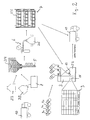
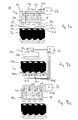
- FIG. 1 a container 2 is shown, which is equipped with a non-contact electronically writable and readable data memory, a so-called transponder 13.
- the container 2 is the train of a new manufacturing process (Pos. 2/1) fed to a filling station 3 (Pos. 2/2).
- the transponder 13 is occupied on the production side with a hardware identifier which lies in a reserved memory area.
- the hardware identifier 13 is burned in a non-erasable PROM (programmable read only memory) of the transponder 13 and thus suitable for unambiguous identification of the transponder 13. Identification can be used to encode (close) and decode (unlock) information, similar to electronic locking systems.
- the container 2 is filled according to a predetermined recipe with toner from one or more toner storage tanks 4a, 4b, 4c.
- the toner can be processed as a solid (powder) or dissolved as a liquid.
- filling data such as a recipe identity number, the filling date, the weight, etc. are encoded in a machine-readable manner and optionally additionally encoded encoded into an EEPROM (Electrically Erasable Progammable Read Only Memory) of the transponder 13 written. Describing the transponder 13 by means of electromagnetic radiation (RF) without contact.
- RF electromagnetic radiation
- All data or specific groups of data on the transponder 13 can password-protected or encrypted in a crypto-mode of the reading, writing station 11 are deposited. In these cases, the corresponding data or data groups can only be read out again by specifying the password and / or an encryption key.
- various modes of operation may be provided in the communication with the transponder 13.
- a first operating mode (crypto mode)
- data is only transmitted in encrypted form.
- a second operating mode (password mode)
- data can only be read from the transponder by specifying a password and / or written to the transponder.
- a password stored on the transponder in the transponder 13 is compared with a password to be input via read station 11. Only when the two passwords are identical, the transponder 13 releases the data stored on it for transmission.
- a password is stored on the transponder 13 or a password already stored on the transponder 13 is reused.
- first public mode only data from the transponder 13 can be read, but not written to it.
- a fourth operating mode (second public mode) both data can be read freely by the transponder 13 and written to the transponder 13.
- the transponder 13 is firmly embedded in the container 2 in the course of the manufacturing process (2/1). If the container 2 made of plastic, so the transponder 13 in the Plastic are welded. But it can also be used in a holder formed on the container 2, be glued or otherwise firmly connected to the container 2.
- the transponder 13 can be regarded as a passive electronic component with fixed and uniquely assigned, individual coding.
- the energy supply of the transponder is carried by the reading, writing station 11 also via radio signals, which are emitted by an antenna of the reading, writing station 11 and are received by an antenna integrated in the transponder 13.
- the reading and writing station determines the presence of the transponder 13 and its individual coding number (identifier).
- the container 2 After filling the container 2 in the filling station 2 (item 2/2), the container 2 is inserted into a printer 1.
- a printer 1 In high-performance printers such as the Océ-Pagestream ® series, which can print up to 500 DIN at 4 pages per minute, a 3 kg toner container 2 is emptied in about 30 minutes.
- the amount of toner removed during printing in the printer 1 is continuously detected, for example by weight measurement of the toner reservoir or by a Sensor that measures the toner level in the toner reservoir.
- a Sensor can be based for example on a capacitive measuring principle.
- the toner reservoir 2 is removed from the printer and cleaned in a cleaning station. Powdery toner residues can be emptied by shaking the toner reservoir 2, depending on requirements, he can additionally cleaned with cleaning brushes or with be rinsed out of a cleaning liquid.
- the container and the cleaning tools are each charged in opposite directions during the cleaning process (eg positive bottle, negative tools).
- the reservoir 2 can accommodate both toner and a mixture of toner and ferromagnetic material (developer).
- the cleaning process for reservoir and the filling process for toner reservoir is in the FIG. 2 explained in more detail.
- the containers 2 are delivered with a transport vehicle 10 and pre-selected in a Pos. 2/3 by means of the data of the transponder 13.
- Completely emptied toner reservoirs are fed directly to the cleaning station 5 (Item 2/4).
- Partially empty toner containers or containers 3 containing spent toner-developer mixtures are discharged into a disposal container 8 and then supplied to the cleaning station 5.
- the containers 2 After cleaning, the containers 2 pass through in a Pos. 2/5 a test station 6, at which they are checked for mechanical damage and leaks. The leak test is carried out by means of an air pressure device. Subsequently, the cleaned and tested containers 2 are stored in a warehouse 7 (2/6). Containers that are to be filled with toner are fed directly to the filling station 3, containers that are to be used again as a disposal container are fed directly to the transport vehicle 10, which delivers the containers towards the printing center. To distinguish between toner storage containers and disposal containers, they are accordingly identified as toner or disposal containers in the transponder.
- a database 9 This includes at least the identification number of the toner bottle as well as the toner type (recipe).
- data about the customer to be delivered as well as the filling date or the like can be stored.
- the database 9 is stored in a central logistics computer which is connected via a computer network to the filling station 3 and / or to the printers connected to the customers. Table 1 shows possibilities for such data as well as the interaction between the involved process units (printer, filling station, container).
- the identification data stored in the PROM area of the transponder 13 and / or the coded key data are read out and, if necessary, checked for correctness on the basis of previous data contained in the database 9.
- the variable data stored in the EEPROM area of the transponder are also checked and updated.
- the amount of toner actually charged in the toner is monitored by means of a suitable measuring system (weight sensor, capacitive level sensor).
- a suitable measuring system weight sensor, capacitive level sensor.
- the necessary variable data such as toner type and toner filling quantity are transferred to the variable storage areas of the transponder 13 and to the database 9.
- the data contained in the database 9 can be used for logistical purposes such. As for the management of circulating containers, for monitoring of toner waste data, etc. are used.
- toners of different colors can be mixed according to given recipes mixed into the reservoir or in intermediate containers, which in turn are used to fill the circulating, equipped with transponders 13 toner reservoirs.
- reading, writing station for transmitting electronic data from and into a transponder can also be another, for example, a label adhesive station for conductive / non-conductive coded labels or a magnetic coding station for processing appropriately equipped reservoir can be provided.
- the data transmission from and to the transponder or container can take place during filling before, during or after the filling process.
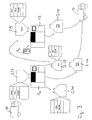
- FIG. 3 the use of a toner reservoir 2 is shown in a printing center.
- the filled toner reservoirs are delivered with a vehicle 10.
- the toner reservoir 2 contain in its electronic memory data about the contained toner (recipe), on the capacity (full) and optional other information such as your own customer identification, the date of filling of the toner, etc. (see Table 1).
- the toner reservoir 2 is then inserted into the toning station of the printer 1a.
- a reading, writing device for reading out the information of the transponder 13 applied to the toner reservoir 2 is provided.
- the read / write device is connected to a microcontroller which interrogates the toner type and checks if this type of toner can be processed.
- printing parameters eg corotron charges in the area of the electrographic developer station
- printing parameters eg corotron charges in the area of the electrographic developer station
- the microcontroller may further process the weight of the toner reservoir as well as the position of the toner reservoir within the printer 1, as long as multiple positions are provided (eg, in color printers).
- the reading and writing device has essentially the same structure as the reading and writing device 11 of the filling station 3 (cf. Fig. 2 ). It is adapted to the attached to the container 2 information carrier (transponder).
- the microcontroller is part of the genset control of an electrophotographic developer station and can communicate with other gensets of the printing device (eg, the control panel, the fuser, or the paper handling device) via a device system bus.
- a container which receives spent toner / developer mixture.
- This container is also provided with a transponder and the basic structure identical to the toner reservoir 2. He (Pos 2/11) is not provided with an indication of a toner formulation but with a disposal identifier that it is a disposal container. As soon as the Container is full (which can be determined for example by a weight measuring or a level sensor) he is provided with information "full", which is written in the transponder of the disposal container 2.
- the printers are preferably networked with each other in terms of data, so that any correction data for a particular toner mixture, which were determined in a first printer (la), can also be used by the second printer (1b).
- this correction data can be transmitted from the printer to the other printer via the data memory (transponder) contained in the toner box.
- the networking can also be extended to the other components of the described printing system, such as the filling station (s), the central computer and so on.
- LAN local area network
- WAN wide area network
- Internet transnational computer networks
- the exchange of data in particular the update of permitted toner types, indications of imminent expiration dates of certain toner batches or improved setting parameters for certain types of toner can be carried out in the course of remote diagnostics without significant effort.
- the fixed assignment of information to the containers by means of a transponder essentially comprises electronic and software engineering mechanisms. These mechanisms can easily be supplemented by mechanical or other electronic mechanisms.
- certain types of toner eg liquid toner
- a color coding can also be added to mechanical geometrical differences in shape, so that a distinction is also possible for the operator operating with the containers.
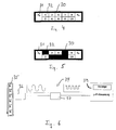
- a label 30 is used, which is adhered to the surface of the reservoir 2.
- the label 30 comprises a plurality of fields (0 a , 0 b , 1 - 10) which can be changed in conductivity.
- the conductivity of the individual fields can be selectively eliminated, for example, by pasting the fields with an insulating film, by overpainting the fields with an insulating paint or by punching out the conductive field from the label 30.
- Two fields (0 a and 0 b ) are the Base contact of the label and are redundant.
- the fields 31 and 32 are coded opposite, for example.
- a corresponding reading station for reading out such a label code has on the printer side spring pins and contact springs, which contact the individual fields of the label electrically after insertion of the toner container in the space provided receiving slot of the printer and scan.
- a conductive connection between the two base contacts 0 a and 0 b shows that a container is present in the printer. If there is no connection between the contact pins of the reading arrangement contacting these fields, then no container is present.
- the contact pins are advantageously pointed at their point of contact with the label when the label is on a horizontal or vertical surface of the container (eg, container bottom) and round when the label is on an oblique side of the container.
- FIG. 6 shows a further alternative embodiment for an information carrier which is mounted on a storage container.
- a magnetic plastic tape 35 consists of alternately magentintestinen areas with north poles N and south poles S.
- the magnetic lines are arranged at a uniform distance from each other.
- coding can be achieved over the length of the magnetized band 35, for example.
- the number of distinguishable Information toner types, toner color, etc.
- Corresponding coding methods are also known, for example, from the coding of cashless payment means (cash cards).
- a reading station 34 may be used, which has a magnetic read head 36 and a comparator 37 for converting the analog signal generated by the read head into digital signals and a controller 39 with a microprocessor for counting the digital pulses and for evaluation and control of the reading process.
- a prefabricated adhesive tape with a fixed magnetic line grid can be used. The coding is carried out by the length of the tape. The tape can easily be glued on and removed. Over the tape length, an optical recognition of the information content is possible. Alternatively, a firmly glued, pressed or sprayed into the container band can be used. When filling the container, the magnetic tape is then first deleted and the number of magnetic bars, ie, the code applied with a magnetic writing head.
- the magnetic read head can be firmly positioned in a container holder.
- the magnetically stored information can then be read when inserting the container into the holder. After a misreading, however, the container must be used again.
- the sensor is movable and thus the magnetic code can also be read from the fixed container.
- the fixed magnetic bar screen is also another coding, z.
- the optical barcode can be represented in particular with a laser ROM card which can be erased and rewritten.
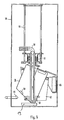
- FIG. 7 a toner supply device 56 of a developer station is shown, which contains a toner reservoir 2.
- the toner 59 therein is sucked out of the toner reservoir 2 by means of a suction pipe 58 and supplied to further components of the developer station 14.
- the suction nozzle 58 is thereby displaced along the guide rods 60, depending on the toner filling level in the toner supply container 2.
- a bellows 61 covers the filling opening of the toner reservoir and thus protects other components of the developer station 14 from contamination.
- the toner reservoir 2 is in a receptacle 62 which is pivotable via a hinge 63 in the interior of the printer. Details of this developer station are in the US 5,074,342 described, the contents of which are hereby incorporated by reference into the description.
- the toner reservoir 2 is provided with a chip card 64, which contains an electronic memory (EEPROM), a drive circuit (IC) and an antenna, via which a wireless data transfer to a reading station 65 can take place.
- the reading station 65 may optionally be attached to the developer station 14 or to the printer housing and is connected to the process control assembly 40 via a cable connection (eg, CAN bus). It can accomplish both the exchange of data with the chip card 64 and a power supply of the chip card 64. Details of such smart cards and reading stations are for example in the US 5,262,712 whose contents Bzgl. Such smart cards and reading stations are hereby also incorporated by reference.
- the toner type for example, the toner type, its color and the level of the container are binary coded and thus stored machine readable.
- the Level is continuously updated during operation of the printing unit by determining the amount of toner removed and subtracting it from the initial level. This makes it possible to remove toner reservoirs partially emptied from the developer station and later reuse in the same or in another device. Instead of with a balance, the exact level can also be determined by the amount of toner removed is determined, for example, based on pumping cycles of a toner delivery pump.
- the energy from the reading station can be capacitively or inductively coupled.
- FIG. 8 there is shown a toner conveying system 16 located within an electrophotographic printer. It conveys the in the containers 2a, 2b and 2c (not shown) in each associated developer stations 15a, 15b and 15c.
- the container 2a contains red toner, which is conveyed via the delivery tube 17a to the developer station 15a, which is prepared for printing in red color and which has a corresponding electronic circuit containing the current color or toner formulation of this developer station.
- an encoding line 18a is provided which is mechanically fixed to the delivery hose 17a with attachment clips 20a.
- the delivery hose 17a With the mechanical or electromechanical connection of the delivery hose 17a to the toner removal components in the region of the toner reservoir 2a and to the developer station 15a, an electrical connection between the microcontoller 21a of the developer station 15a and electronic or electromechanical components of a toner delivery unit 22a made.
- the toner delivery unit 22a can in turn be connected via a connecting line 23 to the reading and writing station 11a, which reads out the transponder 13a on the container 2a.
- connection 23a serves for the correct association between a toner container 2a and its toner conveying unit 22a.
- the connection 18a serves for the correct association between toner conveying unit 22a, conveying hose 17a and developer station 15a. If the connection 23a is missing, the toner formulation can be transferred via the lines 23a and 18a via a system bus 24 of the printer from the reading station 11a to the controller 21a of the developer station. There (or in a higher-level central printer control) is then checked whether the toner formulation is acceptable and possibly released the developer station for printing.
- the antenna 12a Within the reading station 11a is the antenna 12a, a drive circuit 25a and a microprocessor 26a, with which energy to the transponder 13a and data between microprocessor 26a and transponder 13a are exchanged without contact.
- a pulse pattern corresponding to the toner formulation, the individual code of the toner reservoir or the like is transferred via the conduit 18a.
- a verification pulse can also be transmitted via a grounding line according to the power-line principle.
- a necessary coupling can be done inductively or capacitively.
- a toner conveying device (22a, 22b) is asked by the device control via the system bus 24 which recipe is currently located in the associated toner supply container 2a, 2b.
- the associated addressed toner delivery unit 22a, 22b sets the relevant tubing 18a, 18b (not shown) to a defined level indicative of the current query (eg, high).
- the associated developer station 15a, 15b must confirm in response that the connected tubing indicates the agreed level. This process is repeated in succession for all other developer stations and toner conveyor units. This process can also take place in the opposite direction. In this method it is achieved that no protocol for data transmission on the hose must be agreed.
- transmission via optical waveguides can also take place.
- a mechanical and / or color coding of the fittings of the hose and the corresponding connections of the developer stations can be made, for. B. round, triangular, square cross section etc ..
- FIG. 9a, 9b and 9c Various variants of a reading and / or writing device are shown which monitor a plurality of juxtaposed toner reservoirs 2a, 2a, 2c and 2d with their associated transponders 13a, 13b, 13c and 13d. It must be ensured that the read, write device assigns each toner reservoir or each position the right transponder.
- each toner reservoir or each position is assigned a separate send, - and receive interface 11a, 11b, 11c and 11d.
- each These interfaces consist of an antenna and an ASIC containing decoders and encoders.
- the antenna is each dimensioned so that transponders can only be achieved up to a maximum distance, in particular up to 5 cm. This maximum range is matched to the distances between the individual transponders attached to the various toner storage containers. In particular, it is smaller than half the distance between two adjacent transponders.
- the interfaces 11a, 11b, 11c and 11d are managed by a common host microcontroller 26.
- each of the interfaces 11a, 11b, 11c and 11d is selected by a select signal and the send and receive readiness for the respective interface is established.
- a single transmitting and receiving unit is designed so that all toner containers with their associated transponders are in the range of a single antenna 12e.
- the toner reservoirs 2a - 2d may only be changed in succession (serial). It is not permissible to remove or attach two or more toner containers at the same time, otherwise the position assignment will be lost in this variant. Also, the containers should not be removed from a switched off device.
- senors 40a, 40b, 40c and 40d which are connected to the common microprocessor 26. They each provide a signal when the associated toner reservoir is inserted or removed.
- the transmitting and receiving unit 11e checks whether a transponder is within reach and if necessary identifies it using its hardware identifier.
- the sensor belonging to the relevant shaft (A, B, C or D) reports to the microcontroller 26 that its shaft has been occupied. With this information and the read identifier of the toner reservoir is uniquely identifiable and writable.
- Each additional container installed is recognized in the same way and the occupancy of the shafts or positions A - D is determined.
- FIG. 9c illustrated embodiment is substantially identical to the in Fig. 9a illustrated example.
- all transmitting, receiving interfaces 11a-11d are equipped with their own microcontrollers 41a, 41b, 41c and 41d, which are each connected to the common microprocessor 26.
- the microprocessor again performs a host function in this arrangement.
- the toner reservoirs are integrated in a holder in which they are to mount, for example.
- the holder may be provided with one or more closures, which must always be opened when a toner reservoir must be changed or removed.
- the opening of the lid or closure triggers an electrical signal, which in turn triggers the data transfer to the transponder.
- a sensor for example, Hall switches can be used.
- the transponder can be provided to electromechanically control a corresponding closure on the holder for the toner reservoir from the central device control.
- the data in the transponder is then updated, in particular the amount of toner currently contained in the toner reservoir is recorded. Only after updating the data is the lock released.
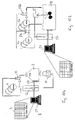
- FIG. 10a variant shown is suitable for filling toner of a color.
- toner reservoirs 2 having a lower toner content, for example, 6 kg, may be filled.
- the filling process is controlled by a filling computer (microprocessor 52), which is connected via a suitable data line or via a network connection to a central computer 51 containing the database 9.
- a test bench sensor 53 scale or capacitive level sensor measures the amount of toner currently contained in the container 2 and reports the status signal to the microprocessor 52. This controls a controllable discharge valve 54.
- the computer 51 can via a data network, for example via a local area network LAN, via wide area network WAN or via an Internet connection to one or more controllers of printing devices, in the filled toner containers are used for printing.
- a printing or copying system can be provided, which forms a data-linked, but locally distributed unit.
- the central database 9 can be used by all devices connected to the network.
- a mixing station in which a responsive microprocessor 52 controls a plurality of drain valves 54a, 54b which control the differently colored toner supply tanks 4a (red), 4b (yellow).
- the respective quantities of toner are introduced into a common toner mixing container 57 and uniformly mixed by means of a mixing motor 55 and a mixer screw.
- the containers may still have readable labels (labels) containing the respective identifier of the transponder integrated in the container, as well as data on the container contents and the date of filling, expiry dates, name of the bottler, owner of the container, intended application location, (Customer) etc.
- labels containing the respective identifier of the transponder integrated in the container, as well as data on the container contents and the date of filling, expiry dates, name of the bottler, owner of the container, intended application location, (Customer) etc.
- a developer station in particular, a according to WO 98/27469 trained station
- Printing consumables are monitored container accurate and substance-specific information used to control the printing process. Expiration dates for the consumables are determined and noticed early at the respective printing location. This avoids waste.
- An information carrier 13, 30, 35, 38 for contactless transmission of data and energy from a data reading and / or writing station 11 to the container 2 is provided on the container.
- a transponder 13 is proposed, which is provided with an individual identification number (hardware identifier). The identification number can be used as part of device control codes.
- the printing or copying system comprises a recycling concept for consumer containers, in particular for electrographic devices.
- One and the same container 2 is used multiple times, the current container contents can be detected at any time by machine container individually.
- the containers 2 are provided with an information carrier 13, 30, 35, 38 which contains machine-readable coded information about the consumable 59 currently or last in the container 2.
- an information carrier a non-contact electronically written and readable module is proposed, in particular a transponder 13.
- the data stored in the transponder can be supplied in parallel via a network to other system components such as a filling station 3, a central computer 51 with a database and the printing or copying devices 1 become.
- Table 1 "Data and interrelations between the locations of data storage" Data on / in the printer Data on the container Database / filling system Detection of valid container (reservation of identifiers), discrimination in case of mixture change, change d.
- Container from one printer to another printer possible ⁇ (Fix, laser trimmed) Identifier ⁇ Registration of the container (for individualization of the container)
- Counter how often transponders between filling and emptying are described, transfer when changing the printer ⁇ Number of times a transponder has been written in one revolution (will be updated on "empty" message or if the container is removed from the printer) ⁇ Counter how often transponders have been described.
- Disposal bit Read / Write, Write only after inquiry on control console Used to pre-determine and monitor the life of the container as it is used as a toner reservoir and can be queried individually by the printer during the inventory control of the container pool, or on a site-by-site basis Disposal bit Read / Write, Write only after inquiry on control console. This allows the premature conversion of the toner to a disposal container in the printer - for exceptions ⁇ Set Disposal Bit (optional) when a container is inserted into a holder on the printer to hold used toner developer mixture ⁇ Conversion of the toner container into disposal container when the disposal bit is set, the container is registered using the identifier as the disposal container, the waste container is kept in the customer's container pool, detection of the disposal bit on delivery, if necessary, separation of residual toner.
Landscapes
- General Physics & Mathematics (AREA)
- Physics & Mathematics (AREA)
- Sustainable Development (AREA)
- Life Sciences & Earth Sciences (AREA)
- Engineering & Computer Science (AREA)
- Microelectronics & Electronic Packaging (AREA)
- Environmental & Geological Engineering (AREA)
- Dry Development In Electrophotography (AREA)
- Control Or Security For Electrophotography (AREA)
- Electrophotography Configuration And Component (AREA)
- Developing Agents For Electrophotography (AREA)
- Accessory Devices And Overall Control Thereof (AREA)
- Packages (AREA)
Applications Claiming Priority (3)
| Application Number | Priority Date | Filing Date | Title |
|---|---|---|---|
| DE19844435 | 1998-09-28 | ||
| DE19844435 | 1998-09-28 | ||
| PCT/EP1999/007193 WO2000019278A1 (de) | 1998-09-28 | 1999-09-28 | Druck- oder kopiersystem mit wiederverwendbarem behälter für verbrauchsmaterial und verfahren zur verwendung des behälters |
Publications (2)
| Publication Number | Publication Date |
|---|---|
| EP1118042A1 EP1118042A1 (de) | 2001-07-25 |
| EP1118042B1 true EP1118042B1 (de) | 2009-01-07 |
Family
ID=7882513
Family Applications (1)
| Application Number | Title | Priority Date | Filing Date |
|---|---|---|---|
| EP99948885A Expired - Lifetime EP1118042B1 (de) | 1998-09-28 | 1999-09-28 | Druck- oder kopiersystem mit wiederverwendbarem behälter für verbrauchsmaterial und verfahren zur verwendung des behälters |
Country Status (10)
| Country | Link |
|---|---|
| US (2) | US6366742B1 (enExample) |
| EP (1) | EP1118042B1 (enExample) |
| JP (1) | JP2002526796A (enExample) |
| CN (2) | CN1320228A (enExample) |
| AT (1) | ATE420391T1 (enExample) |
| CA (1) | CA2345576C (enExample) |
| DE (2) | DE59914945D1 (enExample) |
| ES (1) | ES2318903T3 (enExample) |
| HK (1) | HK1041527A1 (enExample) |
| WO (1) | WO2000019278A1 (enExample) |
Families Citing this family (61)
| Publication number | Priority date | Publication date | Assignee | Title |
|---|---|---|---|---|
| US6494562B1 (en) * | 1998-09-03 | 2002-12-17 | Hewlett-Packard Company | Method and apparatus for identifying a sales channel |
| US6366742B1 (en) * | 1998-09-28 | 2002-04-02 | OCé PRINTING SYSTEMS GMBH | Printing or copying system with a reusable container for consumable materials and method for using said container |
| JP2000298711A (ja) * | 1999-04-12 | 2000-10-24 | Development Bank Of Japan | 反射波解析システム並びに反射波スキャナー |
| DE50000965D1 (de) * | 2000-05-05 | 2003-01-30 | Edomat Deutschland Treuhand Un | Verfahren zur Verwaltung von zu überprüfenden Geräten der Luftfahrtindustrie |
| EP1160619A3 (en) * | 2000-06-02 | 2002-04-17 | Eastman Kodak Company | Transmitting process parameters for imaging |
| US6685296B2 (en) * | 2000-06-16 | 2004-02-03 | Canon Kabushiki Kaisha | Ink tank and ink jet recording apparatus provided with the same |
| US6694106B2 (en) * | 2001-02-19 | 2004-02-17 | Canon Kabushiki Kaisha | Image processing apparatus, a unit used in the apparatus, and a memory device mounted on the unit |
| US20020154915A1 (en) * | 2001-04-24 | 2002-10-24 | Bullock Michael L. | Memory on a container for a consumable substance used to designate recycle information and method |
| US7221473B2 (en) * | 2001-08-03 | 2007-05-22 | Hewlett-Packard Development Company, L.P. | Printing system for updating printing characteristics with a printing consumable |
| JP3941620B2 (ja) * | 2001-08-31 | 2007-07-04 | 株式会社デンソーウェーブ | Idタグ内蔵電子機器 |
| US20030051767A1 (en) * | 2001-09-19 | 2003-03-20 | Unilever Home And Personal Care Usa | Package and system |
| US6685298B2 (en) * | 2001-09-28 | 2004-02-03 | Hewlett-Packard Development Company, L.P. | Method and apparatus for preventing theft of replaceable printing components |
| MXPA02011493A (es) * | 2001-11-28 | 2005-02-17 | Seiko Epson Corp | Comunicacion sin contacto entre el dispositivo y el cartucho que contiene componente consumible. |
| DE10211080A1 (de) | 2002-03-13 | 2003-10-09 | Oce Printing Systems Gmbh | Verfahren, Gerätesysteme und Computerprogramme zum Erzeugen gedruckter Dokumente mit einer eindeutigen Kennung |
| JP4039900B2 (ja) * | 2002-07-02 | 2008-01-30 | 株式会社リコー | トナー供給システム及び移送手段 |
| US6789864B2 (en) * | 2002-08-13 | 2004-09-14 | Hewlett-Packard Development Company, L.P. | Systems and methods for refilling printing cartridges |
| US7589850B2 (en) * | 2002-12-30 | 2009-09-15 | Lexmark International, Inc. | Licensing method for use with an imaging device |
| US6685290B1 (en) * | 2003-01-30 | 2004-02-03 | Hewlett-Packard Development Company, L.P. | Printer consumable having data storage for static and dynamic calibration data, and methods |
| US7240995B2 (en) * | 2003-05-06 | 2007-07-10 | Lexmark International, Inc. | Method of authenticating a consumable |
| DE10328600A1 (de) | 2003-06-25 | 2005-01-20 | OCé PRINTING SYSTEMS GMBH | Verfahren und Vorrichtung zum Fördern von Tonermaterial vorzugsweise in einem elektrofotografischen Drucker oder Kopierer |
| US20050034606A1 (en) * | 2003-08-15 | 2005-02-17 | Jean-Paul In Albon | Coffee machine |
| JP4707373B2 (ja) * | 2003-12-16 | 2011-06-22 | 株式会社リコー | 電子装置、電子装置の制御方法、プログラム、記録媒体、管理システム、および交換部材 |
| US7136608B2 (en) * | 2003-12-19 | 2006-11-14 | Steven Miller | Removable toner cartridge universal adapter |
| KR100601653B1 (ko) * | 2003-12-27 | 2006-07-14 | 삼성전자주식회사 | 비인증 토너 충전 방지 방법 및 장치 |
| DE102004003859A1 (de) * | 2004-01-26 | 2005-08-18 | OCé PRINTING SYSTEMS GMBH | Verfahren, Vorrichtung, Computersystem und Computerprogrammprodukt zum Steuern eines Materialflusses |
| JP4483349B2 (ja) * | 2004-03-08 | 2010-06-16 | 富士ゼロックス株式会社 | カートリッジ |
| US8099791B1 (en) | 2004-06-25 | 2012-01-17 | Lexmark International, Inc. | Method of authenticating a consumable in an imaging device |
| US9296214B2 (en) | 2004-07-02 | 2016-03-29 | Zih Corp. | Thermal print head usage monitor and method for using the monitor |
| JP5016189B2 (ja) * | 2004-08-03 | 2012-09-05 | 株式会社リコー | 電子装置、電子装置の制御方法、プログラム及び記録媒体 |
| DE102004064015B4 (de) * | 2004-08-16 | 2013-08-01 | Oce Printing Systems Gmbh | Behälter zur Aufnahme von Verbrauchsmaterial insbesondere für Druck-oder Kopiervorrichtungen |
| JP2006209060A (ja) * | 2004-12-28 | 2006-08-10 | Ricoh Co Ltd | 容器収納装置、該容器収納装置を備えた搬送装置及び画像形成装置 |
| US20060190324A1 (en) * | 2005-02-24 | 2006-08-24 | Lexmark International, Inc. | Method for providing reduced cost imaging to customers |
| JP4600087B2 (ja) * | 2005-03-01 | 2010-12-15 | ブラザー工業株式会社 | 現像カートリッジのリフィル方法 |
| DE102005012294B3 (de) * | 2005-03-17 | 2006-08-17 | Technotrans Ag | Druckmaschine |
| US8203449B2 (en) * | 2005-03-30 | 2012-06-19 | Samsung Electronics Co., Ltd. | RF-ID tag reading system for using password and method thereof |
| US20060285132A1 (en) * | 2005-06-21 | 2006-12-21 | Samsung Electronics Co., Ltd. | Electrophotographic image forming apparatus |
| JP2007094003A (ja) * | 2005-09-29 | 2007-04-12 | Seiko Epson Corp | 品質未確認の消耗品カートリッジを検出する画像形成装置及びその消耗品カートリッジ |
| US8721203B2 (en) * | 2005-10-06 | 2014-05-13 | Zih Corp. | Memory system and method for consumables of a printer |
| DE102006007304B3 (de) | 2006-02-16 | 2007-09-13 | OCé PRINTING SYSTEMS GMBH | Anordnung zur Förderung von Toner aus einem Tonervorratsbehälter in einen Toneraufnahmebehälter insbesondere bei einer Druck- oder Kopiereinrichtung |
| DE102006017846B3 (de) | 2006-04-18 | 2008-01-03 | OCé PRINTING SYSTEMS GMBH | Elektrografische Druckeinrichtung aus mindestens einem Druckwerk mit einer Mehrzahl von Entwicklerstationen |
| DE102006017847B3 (de) * | 2006-04-18 | 2008-01-03 | OCé PRINTING SYSTEMS GMBH | Verfahren zur Versorgung von Entwicklerstationen mit Toner bei einer elektrografischen Druckeinrichtung |
| US7865264B2 (en) * | 2007-06-01 | 2011-01-04 | Microblend Techologies, Inc. | Method and apparatus for matching amount and type of paint component in a paint manufacturing system |
| US10295946B2 (en) * | 2007-07-31 | 2019-05-21 | Stephen L. Testardi | Warranty entitlement of image-forming device consumable item |
| DE102008051744B4 (de) | 2008-10-15 | 2015-11-12 | Océ Printing Systems GmbH & Co. KG | Anordnung zur Herstellung einer Verbindung zwischen einem Tonervorratsbehälter und einem den Tonervorratsbehälter verschließenden Deckel |
| JP5501052B2 (ja) * | 2010-03-24 | 2014-05-21 | キヤノン株式会社 | 通信装置、通信装置の制御方法、プログラム |
| US8744283B2 (en) * | 2010-05-04 | 2014-06-03 | Kabushiki Kaisha Toshiba | Image forming apparatus and image forming method |
| US9098216B2 (en) | 2012-04-25 | 2015-08-04 | Hewlett-Packard Development Company, L.P. | Printer functionality enablement |
| CN104417072B (zh) * | 2013-08-30 | 2017-02-08 | 珠海纳思达企业管理有限公司 | 存储器组、耗材芯片、耗材芯片组和成像盒 |
| WO2015102793A1 (en) * | 2013-12-03 | 2015-07-09 | Static Control Components, Inc. | Network printer system |
| US10592289B2 (en) | 2014-10-31 | 2020-03-17 | Hewlett-Packard Development Company, L.P. | Providing auxiliary services or functionality on an apparatus |
| US20160120758A1 (en) * | 2014-11-05 | 2016-05-05 | Bo Pi | Smart pill container, control method and system |
| CN104731477A (zh) * | 2015-03-24 | 2015-06-24 | 上海富士施乐有限公司 | 一种复印机参数调试方法 |
| EP3331766A1 (de) | 2015-08-06 | 2018-06-13 | MULTIVAC Sepp Haggenmüller SE & Co. KG | Selbststeuernde verpackungsmaschine und verfahren dafür |
| US9606488B1 (en) * | 2016-01-19 | 2017-03-28 | Xerox Corporation | System for refilling replenisher cartridge |
| CN105882155A (zh) * | 2016-04-15 | 2016-08-24 | 珠海美佳音科技有限公司 | 耗材芯片、处理盒、成像设备和方法 |
| CN109070475B (zh) * | 2016-05-12 | 2021-07-09 | 惠普发展公司,有限责任合伙企业 | 增材制造材料管理站 |
| US10448938B2 (en) | 2016-06-16 | 2019-10-22 | Phillips Medical, LLC | Methods and systems for sealing a puncture of a vessel |
| CN110275401B (zh) * | 2018-03-15 | 2022-10-28 | 柯尼卡美能达办公系统研发(无锡)有限公司 | 可选装置监视装置、图像形成装置以及监视方法 |
| WO2020139323A1 (en) * | 2018-12-26 | 2020-07-02 | Hewlett-Packard Development Company, L.P. | Fluid dispensing systems |
| DE102019123585A1 (de) * | 2019-09-03 | 2021-03-04 | Andreas Berger | Verfahren und System zur Steuerung eines Mehrwegbehälterkreislaufs |
| WO2024043893A1 (en) * | 2022-08-25 | 2024-02-29 | Hewlett-Packard Development Company, L.P. | Toner cartridges including aggregated undeveloped toners of different colors |
Family Cites Families (24)
| Publication number | Priority date | Publication date | Assignee | Title |
|---|---|---|---|---|
| JPS62173482A (ja) * | 1986-01-28 | 1987-07-30 | Ricoh Co Ltd | 静電記録装置のトナ−補給装置 |
| JPS63212956A (ja) * | 1987-02-27 | 1988-09-05 | Bando Chem Ind Ltd | 電子写真記録装置 |
| US5049898A (en) * | 1989-03-20 | 1991-09-17 | Hewlett-Packard Company | Printhead having memory element |
| US4961088A (en) * | 1989-04-20 | 1990-10-02 | Xerox Corporation | Monitor/warranty system for electrostatographic reproducing machines using replaceable cartridges |
| DE4021242C2 (de) * | 1989-07-04 | 1996-10-17 | Ricoh Kk | Elektrofotografisches Druck- oder Kopiergerät mit austauschbarer Prozeßeinheit |
| JPH03161766A (ja) * | 1989-11-20 | 1991-07-11 | Sanyo Electric Co Ltd | 遠隔管理装置 |
| JP2985205B2 (ja) * | 1990-01-25 | 1999-11-29 | ミノルタ株式会社 | 画像形成装置 |
| JPH03230172A (ja) * | 1990-02-05 | 1991-10-14 | Seiko Epson Corp | 画像形成装置 |
| US5208631A (en) | 1991-12-09 | 1993-05-04 | Xerox Corporation | High light color toner identification scheme |
| US5289242A (en) * | 1992-11-17 | 1994-02-22 | Hewlett-Packard | Method and system for identifying the type of toner print cartridges loaded into electrophotographic printers |
| JPH07168513A (ja) | 1992-11-26 | 1995-07-04 | Canon Inc | プロセスカートリッジ及び画像形成装置 |
| JP3279770B2 (ja) * | 1993-10-27 | 2002-04-30 | 株式会社リコー | 電子写真記録装置 |
| JP3230172B2 (ja) | 1993-11-16 | 2001-11-19 | 富士通株式会社 | パラレルデータのシリアル同期保護回路 |
| JPH07234578A (ja) * | 1994-02-24 | 1995-09-05 | Ricoh Co Ltd | 電子写真記録装置 |
| US5512988A (en) * | 1994-10-31 | 1996-04-30 | Xerox Corporation | Apparatus and method for controlling development of developer material on a photoreceptive member |
| US5699091A (en) * | 1994-12-22 | 1997-12-16 | Hewlett-Packard Company | Replaceable part with integral memory for usage, calibration and other data |
| US5995772A (en) * | 1996-02-16 | 1999-11-30 | Lexmark International Inc. | Imaging apparatus cartridge including an encoded device |
| US5930553A (en) * | 1997-04-25 | 1999-07-27 | Hewlett-Packard Company | Image forming and office automation device consumable with memory |
| JPH09314828A (ja) * | 1996-05-30 | 1997-12-09 | Ricoh Co Ltd | インクジェット記録装置及び記録ヘッドユニット |
| JPH10161411A (ja) | 1996-12-05 | 1998-06-19 | Ricoh Co Ltd | 画像形成装置 |
| JPH10221938A (ja) * | 1997-02-03 | 1998-08-21 | Toshiba Chem Corp | トナーカートリッジ |
| US6227643B1 (en) * | 1997-05-20 | 2001-05-08 | Encad, Inc. | Intelligent printer components and printing system |
| US5974500A (en) * | 1997-11-14 | 1999-10-26 | Atmel Corporation | Memory device having programmable access protection and method of operating the same |
| US6366742B1 (en) * | 1998-09-28 | 2002-04-02 | OCé PRINTING SYSTEMS GMBH | Printing or copying system with a reusable container for consumable materials and method for using said container |
-
1999
- 1999-09-28 US US09/485,331 patent/US6366742B1/en not_active Expired - Lifetime
- 1999-09-28 CN CN99811472A patent/CN1320228A/zh active Pending
- 1999-09-28 CA CA002345576A patent/CA2345576C/en not_active Expired - Fee Related
- 1999-09-28 ES ES99948885T patent/ES2318903T3/es not_active Expired - Lifetime
- 1999-09-28 HK HK02103195.5A patent/HK1041527A1/zh unknown
- 1999-09-28 EP EP99948885A patent/EP1118042B1/de not_active Expired - Lifetime
- 1999-09-28 JP JP2000572724A patent/JP2002526796A/ja active Pending
- 1999-09-28 WO PCT/EP1999/007193 patent/WO2000019278A1/de not_active Ceased
- 1999-09-28 DE DE59914945T patent/DE59914945D1/de not_active Expired - Lifetime
- 1999-09-28 CN CN2008100838954A patent/CN101241339B/zh not_active Expired - Fee Related
- 1999-09-28 AT AT99948885T patent/ATE420391T1/de not_active IP Right Cessation
- 1999-09-28 DE DE19981945T patent/DE19981945D2/de not_active Expired - Fee Related
-
2002
- 2002-01-15 US US10/047,820 patent/US6535697B2/en not_active Expired - Lifetime
Also Published As
| Publication number | Publication date |
|---|---|
| CA2345576A1 (en) | 2000-04-06 |
| CA2345576C (en) | 2008-02-12 |
| WO2000019278A1 (de) | 2000-04-06 |
| EP1118042A1 (de) | 2001-07-25 |
| WO2000019278A9 (de) | 2000-06-22 |
| CN101241339A (zh) | 2008-08-13 |
| US6366742B1 (en) | 2002-04-02 |
| CN101241339B (zh) | 2012-04-18 |
| HK1120117A1 (en) | 2009-03-20 |
| CN1320228A (zh) | 2001-10-31 |
| ES2318903T3 (es) | 2009-05-01 |
| US6535697B2 (en) | 2003-03-18 |
| JP2002526796A (ja) | 2002-08-20 |
| US20020110379A1 (en) | 2002-08-15 |
| ATE420391T1 (de) | 2009-01-15 |
| DE19981945D2 (de) | 2002-04-11 |
| HK1041527A1 (zh) | 2002-07-12 |
| DE59914945D1 (de) | 2009-02-26 |
Similar Documents
| Publication | Publication Date | Title |
|---|---|---|
| EP1118042B1 (de) | Druck- oder kopiersystem mit wiederverwendbarem behälter für verbrauchsmaterial und verfahren zur verwendung des behälters | |
| EP0970406B2 (de) | Druck- oder kopiergerät mit austauschbaren, eine identifizierungsanordnung aufweisenden teilaggregaten, verfahren zum betrieb eines solchen geräts sowie ein tonerbehälter zur verwendung in einem solchen gerät | |
| DE69826903T2 (de) | Verfahren zum Betrieb eines Druckgerätes | |
| DE69526613T2 (de) | Informationswegregelkreis für ein System, das medizinische Flüssigkeiten ausliefert | |
| DE69411207T2 (de) | Überwachungssystem mit Doppelspeicher für elektrostatographische Wiedergabegeräte mit austauschbaren Kassetten | |
| EP2571547B1 (de) | Medizinische behandlungsanordnung | |
| DE60102344T2 (de) | Sicherheitssystem für auswechselbare Komponente | |
| DE69816692T2 (de) | Verwaltungssystem für Fixiermodul in einem digitalen Drucker | |
| WO1999048694A1 (de) | Tintenstrahldrucker für die beschriftung von waren | |
| EP2598013B1 (de) | Reinigungsvorrichtung | |
| EP1103924B1 (de) | Verfahren zum Schutz eines Gerätes vor einem Betreiben mit unzulässigem Verbrauchsmaterial und Anordnung zur Durchführung des Verfahrens | |
| DE69017549T2 (de) | Verfahren und Apparat zur Verwaltung von Müllbehältern. | |
| DE60202463T2 (de) | Überwachung eines flüssigkeitsverbrauches | |
| EP1711917A1 (de) | Verfahren, vorrichtung, computersystem und computerprogrammprodukt zum steuern eines materialflusses | |
| EP1103923A2 (de) | Verfahren zum automatischen Bestellen von Verbrauchsmaterial und Anordnung zur Durchführung des Verfahrens | |
| DE19958946B4 (de) | Verfahren zum Piraterieschutz eines Gerätes | |
| EP2010970B1 (de) | Elektrografische druckeinrichtung aus mindestens einem druckwerk mit einer mehrzahl von entwicklerstationen | |
| DE102017205579B4 (de) | Verarbeitungsmaschinensystem und Verfahren zum Betreiben eines Verarbeitungsmaschinensystems | |
| DE602004008996T2 (de) | Druckermodul mit eingebauter Intelligenz | |
| DE102018204918A1 (de) | Verarbeitungsmaschinensystem und Verfahren zum Betreiben eines Verarbeitungsmaschinensystems | |
| DE102017205580B4 (de) | Verarbeitungsmaschinensystem und Verfahren zum Betreiben eines Verarbeitungsmaschinensystems | |
| DE602005005470T2 (de) | Verfahren zum bestätigen der einhaltung von garantiebedingungen und zur sicherung des einsatzes kompatibler tinten | |
| DE102018211788A1 (de) | Behälterdeckel verbindbar mit einem Tintenbehälter einer Behälterdirektdruckmaschine | |
| DE102021122334A1 (de) | Verfahren zum Vorgeben einer Preisinformation sowie Produktverpackungskennzeichnungseinrichtung und Produktabfüllanlage | |
| DE102017205578B4 (de) | Verarbeitungsmaschinensystem und Betriebsverfahren eines Verarbeitungsmaschinensystems |
Legal Events
| Date | Code | Title | Description |
|---|---|---|---|
| PUAI | Public reference made under article 153(3) epc to a published international application that has entered the european phase |
Free format text: ORIGINAL CODE: 0009012 |
|
| 17P | Request for examination filed |
Effective date: 20010427 |
|
| AK | Designated contracting states |
Kind code of ref document: A1 Designated state(s): AT BE CH CY DE DK ES FI FR GB GR IE IT LI LU MC NL PT SE |
|
| 17Q | First examination report despatched |
Effective date: 20070904 |
|
| GRAP | Despatch of communication of intention to grant a patent |
Free format text: ORIGINAL CODE: EPIDOSNIGR1 |
|
| GRAS | Grant fee paid |
Free format text: ORIGINAL CODE: EPIDOSNIGR3 |
|
| GRAA | (expected) grant |
Free format text: ORIGINAL CODE: 0009210 |
|
| AK | Designated contracting states |
Kind code of ref document: B1 Designated state(s): AT BE CH CY DE DK ES FI FR GB GR IE IT LI LU MC NL PT SE |
|
| REG | Reference to a national code |
Ref country code: GB Ref legal event code: FG4D Free format text: NOT ENGLISH |
|
| REG | Reference to a national code |
Ref country code: CH Ref legal event code: EP |
|
| REG | Reference to a national code |
Ref country code: IE Ref legal event code: FG4D Free format text: LANGUAGE OF EP DOCUMENT: GERMAN |
|
| REF | Corresponds to: |
Ref document number: 59914945 Country of ref document: DE Date of ref document: 20090226 Kind code of ref document: P |
|
| REG | Reference to a national code |
Ref country code: ES Ref legal event code: FG2A Ref document number: 2318903 Country of ref document: ES Kind code of ref document: T3 |
|
| PG25 | Lapsed in a contracting state [announced via postgrant information from national office to epo] |
Ref country code: NL Free format text: LAPSE BECAUSE OF FAILURE TO SUBMIT A TRANSLATION OF THE DESCRIPTION OR TO PAY THE FEE WITHIN THE PRESCRIBED TIME-LIMIT Effective date: 20090107 |
|
| NLV1 | Nl: lapsed or annulled due to failure to fulfill the requirements of art. 29p and 29m of the patents act | ||
| PG25 | Lapsed in a contracting state [announced via postgrant information from national office to epo] |
Ref country code: FI Free format text: LAPSE BECAUSE OF FAILURE TO SUBMIT A TRANSLATION OF THE DESCRIPTION OR TO PAY THE FEE WITHIN THE PRESCRIBED TIME-LIMIT Effective date: 20090107 |
|
| REG | Reference to a national code |
Ref country code: IE Ref legal event code: FD4D |
|
| PG25 | Lapsed in a contracting state [announced via postgrant information from national office to epo] |
Ref country code: SE Free format text: LAPSE BECAUSE OF FAILURE TO SUBMIT A TRANSLATION OF THE DESCRIPTION OR TO PAY THE FEE WITHIN THE PRESCRIBED TIME-LIMIT Effective date: 20090407 Ref country code: PT Free format text: LAPSE BECAUSE OF FAILURE TO SUBMIT A TRANSLATION OF THE DESCRIPTION OR TO PAY THE FEE WITHIN THE PRESCRIBED TIME-LIMIT Effective date: 20090608 |
|
| PG25 | Lapsed in a contracting state [announced via postgrant information from national office to epo] |
Ref country code: IE Free format text: LAPSE BECAUSE OF FAILURE TO SUBMIT A TRANSLATION OF THE DESCRIPTION OR TO PAY THE FEE WITHIN THE PRESCRIBED TIME-LIMIT Effective date: 20090107 Ref country code: DK Free format text: LAPSE BECAUSE OF FAILURE TO SUBMIT A TRANSLATION OF THE DESCRIPTION OR TO PAY THE FEE WITHIN THE PRESCRIBED TIME-LIMIT Effective date: 20090107 |
|
| PLBE | No opposition filed within time limit |
Free format text: ORIGINAL CODE: 0009261 |
|
| STAA | Information on the status of an ep patent application or granted ep patent |
Free format text: STATUS: NO OPPOSITION FILED WITHIN TIME LIMIT |
|
| 26N | No opposition filed |
Effective date: 20091008 |
|
| BERE | Be: lapsed |
Owner name: OCE PRINTING SYSTEMS G.M.B.H. Effective date: 20090930 |
|
| PG25 | Lapsed in a contracting state [announced via postgrant information from national office to epo] |
Ref country code: MC Free format text: LAPSE BECAUSE OF NON-PAYMENT OF DUE FEES Effective date: 20090930 |
|
| REG | Reference to a national code |
Ref country code: CH Ref legal event code: PL |
|
| PG25 | Lapsed in a contracting state [announced via postgrant information from national office to epo] |
Ref country code: BE Free format text: LAPSE BECAUSE OF NON-PAYMENT OF DUE FEES Effective date: 20090930 |
|
| PG25 | Lapsed in a contracting state [announced via postgrant information from national office to epo] |
Ref country code: LI Free format text: LAPSE BECAUSE OF NON-PAYMENT OF DUE FEES Effective date: 20090930 Ref country code: GR Free format text: LAPSE BECAUSE OF FAILURE TO SUBMIT A TRANSLATION OF THE DESCRIPTION OR TO PAY THE FEE WITHIN THE PRESCRIBED TIME-LIMIT Effective date: 20090408 Ref country code: CH Free format text: LAPSE BECAUSE OF NON-PAYMENT OF DUE FEES Effective date: 20090930 |
|
| PG25 | Lapsed in a contracting state [announced via postgrant information from national office to epo] |
Ref country code: AT Free format text: LAPSE BECAUSE OF NON-PAYMENT OF DUE FEES Effective date: 20090928 |
|
| PG25 | Lapsed in a contracting state [announced via postgrant information from national office to epo] |
Ref country code: IT Free format text: LAPSE BECAUSE OF FAILURE TO SUBMIT A TRANSLATION OF THE DESCRIPTION OR TO PAY THE FEE WITHIN THE PRESCRIBED TIME-LIMIT Effective date: 20090107 |
|
| PG25 | Lapsed in a contracting state [announced via postgrant information from national office to epo] |
Ref country code: LU Free format text: LAPSE BECAUSE OF NON-PAYMENT OF DUE FEES Effective date: 20090928 |
|
| PG25 | Lapsed in a contracting state [announced via postgrant information from national office to epo] |
Ref country code: CY Free format text: LAPSE BECAUSE OF FAILURE TO SUBMIT A TRANSLATION OF THE DESCRIPTION OR TO PAY THE FEE WITHIN THE PRESCRIBED TIME-LIMIT Effective date: 20090107 |
|
| REG | Reference to a national code |
Ref country code: DE Ref legal event code: R082 Ref document number: 59914945 Country of ref document: DE Representative=s name: PATENTANWAELTE SCHAUMBURG, THOENES, THURN, LAN, DE |
|
| REG | Reference to a national code |
Ref country code: DE Ref legal event code: R082 Ref document number: 59914945 Country of ref document: DE Representative=s name: SCHAUMBURG UND PARTNER PATENTANWAELTE MBB, DE Effective date: 20130820 Ref country code: DE Ref legal event code: R082 Ref document number: 59914945 Country of ref document: DE Representative=s name: SCHAUMBURG & PARTNER PATENTANWAELTE MBB, DE Effective date: 20130820 Ref country code: DE Ref legal event code: R082 Ref document number: 59914945 Country of ref document: DE Representative=s name: SCHAUMBURG & PARTNER PATENTANWAELTE GBR, DE Effective date: 20130820 Ref country code: DE Ref legal event code: R082 Ref document number: 59914945 Country of ref document: DE Representative=s name: PATENTANWAELTE SCHAUMBURG, THOENES, THURN, LAN, DE Effective date: 20130820 Ref country code: DE Ref legal event code: R081 Ref document number: 59914945 Country of ref document: DE Owner name: OCE PRINTING SYSTEMS GMBH & CO. KG, DE Free format text: FORMER OWNER: OCE PRINTING SYSTEMS GMBH, 85586 POING, DE Effective date: 20130820 |
|
| REG | Reference to a national code |
Ref country code: ES Ref legal event code: PC2A Owner name: OCE PRINTING SYSTEMS GMBH & CO. KG Effective date: 20140122 |
|
| REG | Reference to a national code |
Ref country code: FR Ref legal event code: TP Owner name: OCE PRINTING SYSTEMS GMBH & CO. KG, DE Effective date: 20140513 |
|
| REG | Reference to a national code |
Ref country code: GB Ref legal event code: 732E Free format text: REGISTERED BETWEEN 20140904 AND 20140910 |
|
| REG | Reference to a national code |
Ref country code: DE Ref legal event code: R082 Ref document number: 59914945 Country of ref document: DE Representative=s name: SCHAUMBURG UND PARTNER PATENTANWAELTE MBB, DE Ref country code: DE Ref legal event code: R082 Ref document number: 59914945 Country of ref document: DE Representative=s name: SCHAUMBURG & PARTNER PATENTANWAELTE MBB, DE Ref country code: DE Ref legal event code: R082 Ref document number: 59914945 Country of ref document: DE Representative=s name: SCHAUMBURG & PARTNER PATENTANWAELTE GBR, DE |
|
| REG | Reference to a national code |
Ref country code: FR Ref legal event code: PLFP Year of fee payment: 18 |
|
| REG | Reference to a national code |
Ref country code: FR Ref legal event code: PLFP Year of fee payment: 19 |
|
| PGFP | Annual fee paid to national office [announced via postgrant information from national office to epo] |
Ref country code: GB Payment date: 20170925 Year of fee payment: 19 Ref country code: FR Payment date: 20170925 Year of fee payment: 19 |
|
| PGFP | Annual fee paid to national office [announced via postgrant information from national office to epo] |
Ref country code: DE Payment date: 20171026 Year of fee payment: 19 |
|
| PGFP | Annual fee paid to national office [announced via postgrant information from national office to epo] |
Ref country code: ES Payment date: 20171003 Year of fee payment: 19 |
|
| REG | Reference to a national code |
Ref country code: DE Ref legal event code: R119 Ref document number: 59914945 Country of ref document: DE |
|
| GBPC | Gb: european patent ceased through non-payment of renewal fee |
Effective date: 20180928 |
|
| PG25 | Lapsed in a contracting state [announced via postgrant information from national office to epo] |
Ref country code: DE Free format text: LAPSE BECAUSE OF NON-PAYMENT OF DUE FEES Effective date: 20190402 |
|
| PG25 | Lapsed in a contracting state [announced via postgrant information from national office to epo] |
Ref country code: FR Free format text: LAPSE BECAUSE OF NON-PAYMENT OF DUE FEES Effective date: 20180930 |
|
| PG25 | Lapsed in a contracting state [announced via postgrant information from national office to epo] |
Ref country code: GB Free format text: LAPSE BECAUSE OF NON-PAYMENT OF DUE FEES Effective date: 20180928 |
|
| REG | Reference to a national code |
Ref country code: ES Ref legal event code: FD2A Effective date: 20191104 |
|
| PG25 | Lapsed in a contracting state [announced via postgrant information from national office to epo] |
Ref country code: ES Free format text: LAPSE BECAUSE OF NON-PAYMENT OF DUE FEES Effective date: 20180929 |