EP1117609B1 - Vorrichtung zum stapeln von bögen - Google Patents
Vorrichtung zum stapeln von bögen Download PDFInfo
- Publication number
- EP1117609B1 EP1117609B1 EP99950582A EP99950582A EP1117609B1 EP 1117609 B1 EP1117609 B1 EP 1117609B1 EP 99950582 A EP99950582 A EP 99950582A EP 99950582 A EP99950582 A EP 99950582A EP 1117609 B1 EP1117609 B1 EP 1117609B1
- Authority
- EP
- European Patent Office
- Prior art keywords
- stacking
- upper belts
- sheets
- stack
- belts
- Prior art date
- Legal status (The legal status is an assumption and is not a legal conclusion. Google has not performed a legal analysis and makes no representation as to the accuracy of the status listed.)
- Expired - Lifetime
Links
- 239000011111 cardboard Substances 0.000 claims description 4
- 239000011087 paperboard Substances 0.000 claims description 4
- 238000005259 measurement Methods 0.000 claims 1
- 238000011144 upstream manufacturing Methods 0.000 abstract 2
- 238000005192 partition Methods 0.000 description 7
- 239000000123 paper Substances 0.000 description 6
- 238000007664 blowing Methods 0.000 description 5
- 238000000926 separation method Methods 0.000 description 4
- 230000001419 dependent effect Effects 0.000 description 3
- 230000000087 stabilizing effect Effects 0.000 description 2
- 230000004323 axial length Effects 0.000 description 1
- 230000015572 biosynthetic process Effects 0.000 description 1
- 230000008878 coupling Effects 0.000 description 1
- 238000010168 coupling process Methods 0.000 description 1
- 238000005859 coupling reaction Methods 0.000 description 1
- 230000000694 effects Effects 0.000 description 1
- 239000000463 material Substances 0.000 description 1
- 238000000034 method Methods 0.000 description 1
- 238000002604 ultrasonography Methods 0.000 description 1
Images



Classifications
-
- B—PERFORMING OPERATIONS; TRANSPORTING
- B65—CONVEYING; PACKING; STORING; HANDLING THIN OR FILAMENTARY MATERIAL
- B65H—HANDLING THIN OR FILAMENTARY MATERIAL, e.g. SHEETS, WEBS, CABLES
- B65H29/00—Delivering or advancing articles from machines; Advancing articles to or into piles
- B65H29/26—Delivering or advancing articles from machines; Advancing articles to or into piles by dropping the articles
-
- B—PERFORMING OPERATIONS; TRANSPORTING
- B65—CONVEYING; PACKING; STORING; HANDLING THIN OR FILAMENTARY MATERIAL
- B65H—HANDLING THIN OR FILAMENTARY MATERIAL, e.g. SHEETS, WEBS, CABLES
- B65H31/00—Pile receivers
- B65H31/20—Pile receivers adjustable for different article sizes
-
- B—PERFORMING OPERATIONS; TRANSPORTING
- B65—CONVEYING; PACKING; STORING; HANDLING THIN OR FILAMENTARY MATERIAL
- B65H—HANDLING THIN OR FILAMENTARY MATERIAL, e.g. SHEETS, WEBS, CABLES
- B65H31/00—Pile receivers
- B65H31/34—Apparatus for squaring-up piled articles
- B65H31/38—Apparatus for vibrating or knocking the pile during piling
-
- B—PERFORMING OPERATIONS; TRANSPORTING
- B65—CONVEYING; PACKING; STORING; HANDLING THIN OR FILAMENTARY MATERIAL
- B65H—HANDLING THIN OR FILAMENTARY MATERIAL, e.g. SHEETS, WEBS, CABLES
- B65H2301/00—Handling processes for sheets or webs
- B65H2301/40—Type of handling process
- B65H2301/42—Piling, depiling, handling piles
- B65H2301/421—Forming a pile
- B65H2301/4217—Forming multiple piles
- B65H2301/42172—Forming multiple piles simultaneously
-
- B—PERFORMING OPERATIONS; TRANSPORTING
- B65—CONVEYING; PACKING; STORING; HANDLING THIN OR FILAMENTARY MATERIAL
- B65H—HANDLING THIN OR FILAMENTARY MATERIAL, e.g. SHEETS, WEBS, CABLES
- B65H2701/00—Handled material; Storage means
- B65H2701/10—Handled articles or webs
- B65H2701/17—Nature of material
- B65H2701/176—Cardboard
Definitions
- the invention relates to a device for stacking sheets, in particular shingled conveyed sheets of paper or cardboard on pallets, with a vertical stationary, at a height above the maximum stacking height above the ground arranged feed conveyor for the sheets, with a lifting and lowering storage platform, on which the stacks are formed, and with stacking elements over the Working width are arranged positionable according to the preamble of the claim 1.
- Devices for cross-cutting paper or cardboard webs are known to end with a stacking device, of which those produced by cross cutting Sheets are placed on stacks with the exact edge.
- the arches are in Scale form transported by a belt conveyor to the stacking area, where it is on Pallets are stacked, which are placed on a storage platform.
- the storage platform is in the frame of the stacking device up to the area of the feed level Arches can be raised and hung down into the corridor area.
- On the storage platform one or more stacks are formed side by side if the paper or Cardboard web additionally in longitudinal direction before cross cutting Single lanes is divided.
- the stack formation elements partly transverse to the sheet running direction, partly longitudinally in the sheet running direction be positioned because their target position depends on the length and / or the width of the sheets to be filed is dependent.
- the dividers are in one Shake to offset the alignment of the sheets on a stack support.
- ejection rollers and Upper bands preferably at regular intervals across the working width are arranged.
- the discharge rollers are in the area of the end of the feed conveyor arranged directly above the feed plane at a distance from each other. she ensure the transfer of the sheets from the feed conveyor to the stacking area.
- To the To guide sheets in the stacking area there are several above the feed level upper belts extending in the direction of transport at least into the stacking area Spaced from each other. For stacking devices for sensitive papers the upper belts extend into the entire stacking area.
- Ejection rollers and Upper bands are preferably arranged in one plane. You are allowed for one safe transport of the sheets not too far apart and not in the Area of the longitudinal edges of the sheet must be positioned as they function as separators and would disrupt dividers.
- Stacking elements the position of which depends on the arc length and the must therefore be positioned in the longitudinal direction, are one or more notice boards, from which the sheet leading edges are aligned. It can also be be necessary to additionally position the dividing plates in the longitudinal direction so that they act on the longitudinal edges at the required position.
- a generic device that it enables the stacking elements to be automatically inserted when the format changes Position transverse direction.
- the device contains a number of itself Transport direction extending towing shafts, being on a towing shaft each two top hinges, two ejection rollers, a notice board and between the top hinges a separating shoe and a separating plate are each mounted. All on one towing shaft stored stacking elements are thus together with the drag shaft in one new transverse position adjusted.
- This solution is structurally complex because the number of upper belts required at the same time the number of stacking elements acting on the longitudinal edges certainly. May, for example, the distance when storing sensitive papers between two top hinges is a maximum of 200 mm, with a working width of approx. 2200 mm for the required number of upper belts more than 10 drag shafts with the stacking elements coupled to it. The only on the stack forming elements (separating shoes, Dividers), the required number of the number of longitudinal edges, that is The number of stacks formed next to each other must be determined in one large number are kept.
- the invention is therefore based on the object of a generic device to improve that a largely automatic transverse positioning of the individual stacking elements with the least possible design effort is possible.
- the top bands are independent of those on the longitudinal edges acting stacking elements adjustable. This enables the number of stacking elements acting on the longitudinal edges of the sheets to be stacked simultaneously limited to their necessary number (number of benefits + 1).
- the separation shoes can be lifted up to an area above the upper straps according to claim 2, it allows this regardless of the upper bands and to move into new transverse positions at the same time.
- each ejection roller is mounted on a holder that also serves as a guide for an upper band serves. This makes it possible to attach the holder to the adjustment device to couple and thus the assigned upper belt without its own coupling device an adjustment of the ejection roller in its new transverse position to drag.
- Claim 5 the top belts at the beginning and at the end of their conveyor line each a common guide roller extending across the working width. The Upper belts can be easily moved across the deflection rollers.
- a partition plate that can be positioned transversely arranged.
- the partition plates have in the embodiment according to claim 7 its own adjustment device for its transverse positioning. If the dividers can also be positioned in the longitudinal direction, this is structurally easier with a separate cross adjustment device. If no positioning in Longitudinal direction is required, the dividers to the cross adjustment of the separating shoes, as they are also on the longitudinal edges of the arches act (claim 8).
- the bulletin board therefore consists of a series of short segments, each in which are positioned transversely together with the top bands.
- Claim 9 contains a particularly advantageous embodiment of a Stacking device in which a continuous bulletin board is used, thus one Cross positioning of bulletin boards is not required.
- the cross adjustment device for the top bands is designed so that they are only predetermined from each other can take spaced transverse positions. Collisions with the continuous Message boards are avoided by making this possible on all possible Transverse positions of the upper bands has recesses through which they are guided can be.
- the bulletin boards can be moved out of the area of the upper belts for their transverse positioning.
- Claim 11 contains a structurally advantageous embodiment of the adjusting device for cross positioning.
- An absolutely measuring position measuring system Claim 12 makes it possible to directly control the individual target positions.
- the stacking device shown is used for stacking continuously in scale form conveyed sheets of paper 1, which are produced in a cross cutting machine were.
- the sheets 1 are the stacking area by a belt conveyor trained feeder 2, the vertically stationary at a height above the maximum stacking height is arranged above the floor.
- the stack 3 will be on Pallets 4 formed, which lie on a storage platform 5.
- the storage platform 5 is in the Frame of the stacking device up to the area of the feed plane of the sheets 1 can be raised and hung down into the hallway.
- the frame of the device consists of two upright stands 6 and two outlet-side stands 7, which are outside the working width on both sides of the machine arranged and at their upper ends via side members 8 and in Fig. 1st not visible cross members are connected.
- the stands 6, 7 limit the stacking area.
- On the inside of each upright 6 is a Cantilever beam 9 suspended vertically movably on pull chains 10, on the horizontal one Support parts, the storage platform 5 is attached.
- An electric motor 11 acts as a lifting drive, preferably a servo motor that extends across a working width in the upper
- a synchronizer shaft extending across the crossbeam has a sprocket 12 on each machine side drives, in which the pull chain 10 is suspended.
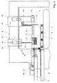
- FIG. 2 The stacking elements and their arrangement are shown in simplified form in FIG. 2:
- upper belts 13 Immediately above the feed level there are several in the direction of transport extending upper belts 13 spaced from each other by the feed conveyor 2 reach at least into the stacking area.
- the upper bands preferably extend 13 over the entire stack area or - as shown in Fig. 2 - so extendable to include the maximum sheet length across the entire stack 3 are enough. In the present exemplary embodiment, they have a width of 30-40 mm on.
- the number of top bands 13 depends on the sheet material and the working width dependent on the stacking device, with the storage of sheets 1 from sensitive Paper the number is sufficient to distance less than To be able to adjust 300 mm between two upper bands 13. All top bands are 13 at the beginning and at the end of their conveying route, all around common Deflection rollers 14, 15 guided, which extend over the entire working width.
- the circumferential storage and two common deflection rollers 14, 15 make it possible to move each upper belt 13 transversely into a new target position.
- the inlet-side deflection roller 14 and the outlet-side deflection roller 15 each mounted in a carriage 16, 17 slidably mounted in the longitudinal direction, so that the position of the deflection roller 15 on the outlet side depends on the The length of the bow can be adjusted without changing the length of the conveying strand.
- each upper belt 13 there is an ejection roller 18 arranged, whose axial length corresponds to the width of the band 13 and so that Upper band 13 is supported on its back.
- Each ejection roller 18 is transverse to one slidably mounted in the frame holder 19, which also serves as a side guide serves for the associated upper band 13. So with an adjustment of the holder 19 with the ejector roller 18 attached to it also the associated upper band 13 in his new position moved.
- Each holder 19 is transversely displaceable on a guide rail stored so that it only predetermined cross positions objected to by each other can take. In the present exemplary embodiment, the distance is two possible positions from each other 100 mm. Since each holder 19 also serves as a guide for the assigned upper belt 13 is used, the upper belts 13 can also in the transverse direction only occupy the previously defined positions.
- the Device separating shoes 20 which has a running edge on each long side have, from which the longitudinal edges of two adjacent arches are bent up.
- the curvature of a sheet 1 on its longitudinal edge has a stabilizing effect and also ensures a safe separation of two adjacent arches 1.
- the separation shoes 20 are at the end of the feed conveyor 2 directly in front of the stacking area in the amount of Infeed level arranged. So that you can act on each long edge, is yours Number one greater than the maximum number of stacks 3 to be formed steplessly displaceable, so that its transverse position is possible Longitudinal edge position can be adjusted. In addition, they are stored so that they can be raised up to the area above the upper belts 13.
- the Raising and lowering takes place by means of vertical piston-cylinder units 37 a separating element 18 is attached to the lower end of each.
- Further stacking elements acting on the longitudinal edges of the sheet are vertical dividers 21, each in the stacking area at the level of the feed level between two stacks 3 and on the two outer longitudinal edges of the outer Stack 3 are arranged. Their number and their transverse positions therefore correspond to that Number of separating shoes 20.
- the separating plates 21 have the task of one edge-accurate storage of the sheets 1 on the stacks 3 to guide the sheets 1 laterally and align.
- the separating plates 21 are usually shaken offset to help align sheets 1 on stacks 3.
- the Partitions 21 are slidably mounted in the frame of the device so that their Positions can be adapted to the respective positions of the longitudinal edges.
- the separating plates 21 are each detachable at the lower end of the vertical piston Piston-cylinder unit 22 attached, by means of which it goes up to the area can be raised above the upper belts 13.
- the cylinder of every piston-cylinder unit 22 is attached to a holder 23 which is slidable on a Crossbar 24 is mounted.
- the crossbar 24 is at both ends attached to a carriage 25 which is displaceable in the longitudinal direction on a longitudinal cross member 8 is hung.
- a drive on the carriage serves as the drive for the longitudinal adjustment of the carriage 25 25 attached electric motor 26, the drive pinion meshes with a rack 27, which is attached to the longitudinal cross member 8 and extends in the longitudinal direction.
- the upper straps 13 are independent of those on the Longitudinal edges acting stacking elements (here dividing shoes 20, dividing plates 21) are adjustable.
- the independent adjustability enables the cross adjustment to automate without too many stacking elements must be kept available.
- Message board 28 arranged on which the sheet leading edges are aligned. So that the position of the bulletin board 28 in the longitudinal direction of the respective arc length can be adjusted, it is suspended longitudinally. It is expedient the bulletin board 28 hung on each side of the carriage 17, in which the outlet-side deflection rollers 15 of the upper belts 13 are mounted. It will be so positioned together with the deflection rollers 15 in the longitudinal direction. As a drive for the An electric motor 29, attached to the carriage 17, serves for longitudinal adjustment Drive pinion also meshes with the rack 27.
- the bulletin board 28 points in at regular intervals at all possible transverse positions of the upper belts 13 open recesses at the bottom through which the upper bands 13 can be guided.
- the distance between two cutouts is therefore also 100 mm.
- the width of the recesses is larger than the width of the Upper bands 13, and they extend from the bottom up to above the range of upper run of the upper belts 13.
- the notice board 28 is by means of a Lifting drive, for example a piston-cylinder unit 30, can be raised so far that its lower edge is above the upper runs of the upper belts 13. This enables transverse positioning of the upper belts 13 regardless of the longitudinal position of the bulletin board 28.
- blowpipes 31 arranged to detach the sheets 1 from the upper straps 13 support with compressed air that blows from above and at the same time the sheets 1 for a trouble-free storage on a stack 3 stabilized.
- a blow pipe 31 is arranged on the upper belts 13, the underside of which Blowing part having blowing nozzles parallel to the top of the stack against the direction of sheet travel extends at least over the rear part of a stack 3.
- the blowpipes 31 each have an upwardly angled feed pipe without blowing nozzles, with which they on a across the working width and a compressed air supply connected Hohitraverse 33 are attached.
- the hollow cross member 33 is on the Carriage 17 attached so that the blowpipes 31 together with the bulletin board 28 and the outlet-side deflection rollers 15 of the upper belts 13 in the longitudinal direction be positioned.
- the blowing nozzles 31 With their feed pipe, the blowing nozzles 31 are in the hollow cross member 32 detachably hooked in so that if necessary before transverse positioning of the top hinges 13 can be easily unhooked and removed. if necessary they are adapted against other blowpipes 31 with a new arc length Blow part replaced and / or hung in the new transverse position.
- the Traverse 32 therefore has a number of closable connecting pieces on its upper side on, in each of which a blow pipe 31 can be hung.
- FIG 3 are the adjustment devices for the individual stacking elements presented in more detail.
- the partition plates 21 and the separating shoes 20 each have their own transverse adjustment device.
- a common adjustment device it is possible to use these two stacking elements with a common adjustment device to be positioned transversely, as they correspond to the position of the longitudinal edges of the Sheets 1 are positioned.
- the three transverse adjustment devices are each constructed in the same way. Matching Parts are labeled with the same reference numbers for simplicity.
- Matching Parts are labeled with the same reference numbers for simplicity.
- Across the working width is a revolving drive by means of a Motors 33 driven belt 34 stored in the frame of the stacking device.
- a piston-cylinder unit 35 attached, which serves the respective element to a strand of the circumferential Band 34 to couple for an adjustment movement.
- the respective stacking elements can be coupled together and from the associated band 34 in their new target position to be promoted. There they are back from the respective band 34 solved and by means of a further piston-cylinder unit on their respective Guide rail clamped to fix it in the desired position.
- each Position measuring system contains a measuring tube 36 which extends over the working width that a magnet is pushed with play, which is attached to the respective holder 19.
- In the measuring tube 36 are generated by current pulses magnetic fields with the Permanent magnets interact and each in the tube 36 by magnetostriction trigger an ultrasound pulse, its duration for the respective position determination is evaluated.
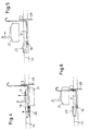
- the dividing shoes 20 and the dividing plates 21 are in one area raised above the upper belts 13 (FIG. 4). Then the Partitions 21 moved longitudinally to the message board 28 in an exchange position ( Figure 5). The separating plates 21 and the blowing tubes 31 are in the changing position exchanged for such shorter length ( Figure 6). After hanging the new one Partitions 21 and blowpipes 31 become the bulletin board 28 and the blowpipes 31 raised to a position above the upper belts 13 and then lengthways moved against the sheet running direction into its new longitudinal soliposition, as in FIG. 7 is indicated.
- the separating shoes 20, the dividers 21 and the blowpipes 31 are now all elements except for the Blowpipes 31 and the notice board 28 extending across the working width moved to their new transverse target positions at the same time.
- the upper straps 13 are thereby carried along by the holder 19 of the ejection rollers 18 since they are each carried by the holder 19 the associated ejection roller 18 are guided.
- the Upper belts 13 moved on the continuous deflection rollers 14, 15. So that she a movement of a holder 19 follow a discharge roller 18, they are during the Transverse adjustment in a circular movement. If the cross-adjustable Stacking elements have reached their target positions, the separation shoes 20, the partition plates 21 and the message board 28 back into their working positions lowered ( Figure 9).
- the stacking device can stack with the sheets 1 in the start new format.
Landscapes
- Engineering & Computer Science (AREA)
- Mechanical Engineering (AREA)
- Pile Receivers (AREA)
- Sheets, Magazines, And Separation Thereof (AREA)
- Forming Counted Batches (AREA)
Description
- Figur 1
- zeigt in schematischer Darstellung die Seitenansicht einer Stapelvorrichtung.
- Figur 2
- zeigt eine etwas vergrößerte Darstellung.
- Figur 3
- zeigt Details der Stapelbildungselemente und ihrer Verstelleinrichtungen.
- Die Figuren 4 bis 9
- zeigen den Ablauf einer Positionierung der Stapelbildungselemente auf ein neues Bogenformat.
Claims (12)
- Vorrichtung zum Stapeln von Bögen (1), insbesondere von geschuppt zugeförderten Papier- oder Kartonbögen auf Paletten (4), mit einem vertikal ortsfesten, in einer Höhe oberhalb der maximalen Stapelhöhe über dem Boden angeordneten Zuförderer (2) für die Bögen (1), einer heb- und senkbaren Ablageplattform (5), auf der die Stapel (3) gebildet werden,
mit einer Reihe von Oberbändern (13), die vom Zuförderer (2) zumindest bis in den Stapelbereich reichen und mit weiteren Stapelbildungselementen, die auf jede Längskante eines Bogens (1) einwirken, wobei die Oberbänder (13) und die weiteren Stapelbildungselemente über die Arbeitsbreite mittels einer Verstelleinrichtung quer positionierbar sind, dadurch gekennzeichnet, dass die Oberbänder (13) unabhängig von den auf die Längskanten einwirkenden Stapelbildungselementen verstellbar sind. - Vorrichtung nach Anspruch 1, dadurch gekennzeichnet, dass am Ende des Zuförderers (2) auf jede Längskante eines Bogens (1) einwirkende Trennschuhe (20) angeordnet sind, die bis in den Bereich oberhalb der Oberbänder (13) anhebbar sind und an eine von der Verstelleinrichtung für die Oberbänder (13) getrennten Verstelleinrichtung für ihre Querpositionierung ankuppelbar sind.
- Vorrichtung nach Anspruch 1 oder 2, dadurch gekennzeichnet, dass am Ende des Zuförderers (2) eine Reihe von Ausstossrollen (18) angeordnet ist, die mit den Oberbändern (13) eine gemeinsame Verstelleinrichtung aufweisen.
- Vorrichtung nach Anspruch 3, dadurch gekennzeichnet, dass jede Ausstossrolle (18) an einem Halter (19) gelagert ist, der zugleich als Führung für ein Oberband (13) dient.
- Vorrichtung nach einem der Ansprüche 1 bis 4, dadurch gekennzeichnet, dass die umlaufend geführten Oberbänder (13) am Anfang und am Ende ihrer Föderstrecke jeweils um eine gemeinsame, sich über die Arbeitsbreite erstreckende Umlenkwalze (14, 15) geführt sind.
- Vorrichtung nach einem der Ansprüche 1 bis 5, dadurch gekennzeichnet, dass im Stapelbereich jeweils im Bereich einer Längskante eines Bogens (1) ein quer positionierbares Trennblech (21) angeordnet ist.
- Vorrichtung nach Anspruch 6 gekennzeichnet durch eine eigene Verstelleinrichtung zum Querpositionieren der Trennbleche (21).
- Vorrichtung nach Anspruch 6, dadurch gekennzeichnet, dass die Trennbleche (21) an die Querverstelleinrichtung der Trennschuhe (18) ankuppelbar sind.
- Vorrichtung nach einem der Ansprüche 1 bis 8, dadurch gekennzeichnet, dass die Oberbänder (13) sich über den gesamten Stapelbereich erstrecken oder verlängerbar sind, sie nur vorbestimmte, voneinander beabstandene Querpositionen einnehmen können, und dass ein sich über die Arbeitsbreite erstreckendes Anschlagbrett (28) für die Bogenvorderkanten vorhanden ist, das in Längsrichtung verstellbar ist und an allen möglichen Querpositionen der Oberbänder (13) Aussparungen aufweist, durch die diese geführt werden können.
- Vorrichtung nach Anspruch 9, dadurch gekennzeichnet, dass das Anschlagbrett (28) nach unten offene Aussparungen aufweist und bis in den Bereich oberhalb der Oberbänder (13) anhebbar ist.
- Vorrichtung nach einem der Ansprüche 1 bis 10, dadurch gekennzeichnet, dass als Verstelleinrichtungen zum Querpositionieren umlaufend angetriebene Bänder (34) quer über die Arbeitsbreite angeordnet sind, an die die jeweiligen Stapelbildungselemente ankuppelbar sind.
- Vorrichtung nach einem der Ansprüche 1 bis 11, dadurch gekennzeichnet, dass jede Verstelleinrichtung ein sich über die Arbeitsbreite erstreckendes absolut messendes Positionsmesssystem zur Steuerung der Positionierbewegung jedes Stapelbildungselements enthält.
Applications Claiming Priority (3)
| Application Number | Priority Date | Filing Date | Title |
|---|---|---|---|
| DE19845850A DE19845850C2 (de) | 1998-10-05 | 1998-10-05 | Vorrichtung zum Stapeln von Bögen |
| DE19845850 | 1998-10-05 | ||
| PCT/EP1999/007259 WO2000020315A1 (de) | 1998-10-05 | 1999-09-30 | Vorrichtung zum stapeln von bögen |
Publications (3)
| Publication Number | Publication Date |
|---|---|
| EP1117609A1 EP1117609A1 (de) | 2001-07-25 |
| EP1117609B1 true EP1117609B1 (de) | 2002-06-05 |
| EP1117609B2 EP1117609B2 (de) | 2007-05-23 |
Family
ID=7883485
Family Applications (1)
| Application Number | Title | Priority Date | Filing Date |
|---|---|---|---|
| EP99950582A Expired - Lifetime EP1117609B2 (de) | 1998-10-05 | 1999-09-30 | Vorrichtung zum stapeln von bögen |
Country Status (6)
| Country | Link |
|---|---|
| US (1) | US6626430B1 (de) |
| EP (1) | EP1117609B2 (de) |
| AT (1) | ATE218495T1 (de) |
| DE (2) | DE19845850C2 (de) |
| ES (1) | ES2183611T5 (de) |
| WO (1) | WO2000020315A1 (de) |
Families Citing this family (6)
| Publication number | Priority date | Publication date | Assignee | Title |
|---|---|---|---|---|
| DE10134423A1 (de) * | 2001-07-19 | 2003-02-06 | Jagenberg Querschneider Gmbh | Vorrichtung zum Stapeln von Bögen, insbesondere von geschuppt zugeförderten Papier- oder Kartonbögen auf Paletten |
| DE10134425A1 (de) * | 2001-07-19 | 2003-02-06 | Jagenberg Querschneider Gmbh | Vorrichtung zum Stapeln von Bögen, insbesondere von geschuppt zugeförderten Papier- oder Kartonbögen auf Paletten |
| DE102004051243A1 (de) * | 2004-10-20 | 2006-05-04 | Bhs Corrugated Maschinen- Und Anlagenbau Gmbh | Stapel-Vorrichtung für Wellpappe-Bögen |
| DE102009045319B4 (de) * | 2009-10-02 | 2018-12-13 | Bw Papersystems Hamburg Gmbh | Formateinstellvorrichtung |
| DE102012214629A1 (de) * | 2012-08-17 | 2014-02-20 | Bielomatik Leuze Gmbh + Co. Kg | Vorrichtung zum Schuppen und Ablegen von Bögen auf einen Stapel |
| JP7458624B2 (ja) * | 2019-11-07 | 2024-04-01 | ホリゾン・インターナショナル株式会社 | 用紙束揃え装置 |
Citations (1)
| Publication number | Priority date | Publication date | Assignee | Title |
|---|---|---|---|---|
| DE4224010A1 (de) * | 1991-08-03 | 1993-02-04 | Will E C H Gmbh & Co | Vorrichtung zum handhaben von bahn- oder bogenmaterial aus papier |
Family Cites Families (2)
| Publication number | Priority date | Publication date | Assignee | Title |
|---|---|---|---|---|
| DE3114414C2 (de) * | 1981-04-09 | 1984-08-09 | Jagenberg-Werke AG, 4000 Düsseldorf | Vorrichtung zum Stapeln von Bögen |
| DE3601295A1 (de) * | 1986-01-17 | 1987-07-23 | Waertsilae Strecker Gmbh | Bogenstapelvorrichtung fuer einstellbare formatbreiten |
-
1998
- 1998-10-05 DE DE19845850A patent/DE19845850C2/de not_active Expired - Fee Related
-
1999
- 1999-09-30 DE DE59901664T patent/DE59901664D1/de not_active Expired - Lifetime
- 1999-09-30 ES ES99950582T patent/ES2183611T5/es not_active Expired - Lifetime
- 1999-09-30 US US09/787,931 patent/US6626430B1/en not_active Expired - Fee Related
- 1999-09-30 AT AT99950582T patent/ATE218495T1/de active
- 1999-09-30 WO PCT/EP1999/007259 patent/WO2000020315A1/de not_active Ceased
- 1999-09-30 EP EP99950582A patent/EP1117609B2/de not_active Expired - Lifetime
Patent Citations (1)
| Publication number | Priority date | Publication date | Assignee | Title |
|---|---|---|---|---|
| DE4224010A1 (de) * | 1991-08-03 | 1993-02-04 | Will E C H Gmbh & Co | Vorrichtung zum handhaben von bahn- oder bogenmaterial aus papier |
Also Published As
| Publication number | Publication date |
|---|---|
| DE59901664D1 (de) | 2002-07-11 |
| WO2000020315A1 (de) | 2000-04-13 |
| ES2183611T5 (es) | 2007-12-16 |
| ATE218495T1 (de) | 2002-06-15 |
| EP1117609A1 (de) | 2001-07-25 |
| EP1117609B2 (de) | 2007-05-23 |
| DE19845850A1 (de) | 2000-04-13 |
| ES2183611T3 (es) | 2003-03-16 |
| DE19845850C2 (de) | 2002-06-20 |
| US6626430B1 (en) | 2003-09-30 |
Similar Documents
| Publication | Publication Date | Title |
|---|---|---|
| DE2443106C2 (de) | Stapelvorrichtung zur Bildung eines Stapels gegeneinander versetzt angeordneter Blattstöße | |
| DE3535113C2 (de) | ||
| EP0847949B1 (de) | Einrichtung zur Bildung eines sich senkrecht zu den stehend aneinandergereihten Druckbogen erstreckenden Stapels | |
| EP0187344A1 (de) | Verfahren und Vorrichtung zum Herstellen einzelner, aus einer zickzackförmig gefalteten Materialbahn bestehender Stapel | |
| EP0350642B1 (de) | Vorrichtung zum Abstapeln von Bögen, insbesondere von Kartonbögen | |
| EP0718231B1 (de) | Vorrichtung zum Stapeln von Bögen, insbesondere von geschuppt zugeförderten Papier- oder Kartonbögen | |
| CH680363A5 (de) | ||
| DE102010053587A1 (de) | Non-Stop-Stab mit Transportband | |
| EP1117609B2 (de) | Vorrichtung zum stapeln von bögen | |
| DE4127854C2 (de) | Vorrichtung zum Zuführen von zwei plattenförmigen Zuschnitten zu einer Tiefziehmaschine | |
| EP0591099B1 (de) | Verfahren und Vorrichtung zur Herstellung gebundener Stapel von Erzeugnissen aus Papier | |
| EP3889087A1 (de) | Sammel- und weiterfördervorrichtung zum sammeln und weiterfördern von blattförmigen druckereiprodukten | |
| EP1528023A1 (de) | Verfahren und Vorrichtung zur Wandlung eines Förderstromes von flachen Gegenständen | |
| DE102011006482A1 (de) | Stapelbildungsvorrichtung | |
| DE2744061C2 (de) | ||
| DE102005002532A1 (de) | Vorrichtung und Verfahren zum automatisierten und zeitgleichen Bereitstellen und Wechseln von mindestens zwei Rollen aus Papierbahnen oder dergleichen für einen nachgeordneten Formatschneider | |
| EP0974543B1 (de) | Einrichtung zur Bildung einer Lücke | |
| DE2940399C2 (de) | Vorrichtung zum Stapeln von Kunststoffbeuteln | |
| EP1412269B1 (de) | Vorrichtung zum stapeln von bögen, insbesondere von geschuppt zugeförderten papier- oder kartonbögen auf paletten | |
| EP1058670B1 (de) | Vorrichtung zum stapeln von bögen | |
| EP1868931A1 (de) | Gruppiervorrichtung | |
| DE102009045319A1 (de) | Formateinstellvorrichtung | |
| DE4235732C2 (de) | Vorrichtung zum Schneiden und Ablegen von bedrucktem Endlospapier | |
| EP1671908B1 (de) | Einrichtung zur Beschickung einer Verarbeitungsvorrichtung mit in einem Förderstrom transportierten Druckprodukten | |
| EP1270261A2 (de) | Verfahren zum Einlegen von zumindest einem Leseband in Buchblocks sowie Vorrichtung zur Durchführung des Verfahrens |
Legal Events
| Date | Code | Title | Description |
|---|---|---|---|
| PUAI | Public reference made under article 153(3) epc to a published international application that has entered the european phase |
Free format text: ORIGINAL CODE: 0009012 |
|
| 17P | Request for examination filed |
Effective date: 20010214 |
|
| AK | Designated contracting states |
Kind code of ref document: A1 Designated state(s): AT BE CH CY DE DK ES FI FR GB GR IE IT LI LU MC NL PT SE |
|
| GRAG | Despatch of communication of intention to grant |
Free format text: ORIGINAL CODE: EPIDOS AGRA |
|
| 17Q | First examination report despatched |
Effective date: 20010911 |
|
| GRAG | Despatch of communication of intention to grant |
Free format text: ORIGINAL CODE: EPIDOS AGRA |
|
| GRAH | Despatch of communication of intention to grant a patent |
Free format text: ORIGINAL CODE: EPIDOS IGRA |
|
| GRAH | Despatch of communication of intention to grant a patent |
Free format text: ORIGINAL CODE: EPIDOS IGRA |
|
| GRAA | (expected) grant |
Free format text: ORIGINAL CODE: 0009210 |
|
| AK | Designated contracting states |
Kind code of ref document: B1 Designated state(s): AT DE DK ES FR GB IT |
|
| REF | Corresponds to: |
Ref document number: 218495 Country of ref document: AT Date of ref document: 20020615 Kind code of ref document: T |
|
| REG | Reference to a national code |
Ref country code: GB Ref legal event code: FG4D Free format text: NOT ENGLISH |
|
| REG | Reference to a national code |
Ref country code: IE Ref legal event code: FG4D Free format text: GERMAN |
|
| REF | Corresponds to: |
Ref document number: 59901664 Country of ref document: DE Date of ref document: 20020711 |
|
| GBT | Gb: translation of ep patent filed (gb section 77(6)(a)/1977) |
Effective date: 20020721 |
|
| RAP2 | Party data changed (patent owner data changed or rights of a patent transferred) |
Owner name: VOITH PAPER JAGENBERG GMBH |
|
| PG25 | Lapsed in a contracting state [announced via postgrant information from national office to epo] |
Ref country code: DK Free format text: LAPSE BECAUSE OF FAILURE TO SUBMIT A TRANSLATION OF THE DESCRIPTION OR TO PAY THE FEE WITHIN THE PRESCRIBED TIME-LIMIT Effective date: 20020905 |
|
| ET | Fr: translation filed | ||
| REG | Reference to a national code |
Ref country code: IE Ref legal event code: FD4D Ref document number: 1117609E Country of ref document: IE |
|
| REG | Reference to a national code |
Ref country code: ES Ref legal event code: FG2A Ref document number: 2183611 Country of ref document: ES Kind code of ref document: T3 |
|
| PLBQ | Unpublished change to opponent data |
Free format text: ORIGINAL CODE: EPIDOS OPPO |
|
| PLBI | Opposition filed |
Free format text: ORIGINAL CODE: 0009260 |
|
| PLBF | Reply of patent proprietor to notice(s) of opposition |
Free format text: ORIGINAL CODE: EPIDOS OBSO |
|
| 26 | Opposition filed |
Opponent name: E.C.H. WILL GMBH Effective date: 20030304 |
|
| REG | Reference to a national code |
Ref country code: GB Ref legal event code: 732E |
|
| PLBB | Reply of patent proprietor to notice(s) of opposition received |
Free format text: ORIGINAL CODE: EPIDOSNOBS3 |
|
| RAP2 | Party data changed (patent owner data changed or rights of a patent transferred) |
Owner name: VOITH PAPER JAGENBERG GMBH |
|
| PLAB | Opposition data, opponent's data or that of the opponent's representative modified |
Free format text: ORIGINAL CODE: 0009299OPPO |
|
| R26 | Opposition filed (corrected) |
Opponent name: E.C.H. WILL GMBH Effective date: 20030304 |
|
| PUAH | Patent maintained in amended form |
Free format text: ORIGINAL CODE: 0009272 |
|
| STAA | Information on the status of an ep patent application or granted ep patent |
Free format text: STATUS: PATENT MAINTAINED AS AMENDED |
|
| 27A | Patent maintained in amended form |
Effective date: 20070523 |
|
| AK | Designated contracting states |
Kind code of ref document: B2 Designated state(s): AT DE DK ES FR GB IT |
|
| GBTA | Gb: translation of amended ep patent filed (gb section 77(6)(b)/1977) | ||
| ET3 | Fr: translation filed ** decision concerning opposition | ||
| REG | Reference to a national code |
Ref country code: ES Ref legal event code: DC2A Date of ref document: 20070823 Kind code of ref document: T5 |
|
| PGFP | Annual fee paid to national office [announced via postgrant information from national office to epo] |
Ref country code: DE Payment date: 20140922 Year of fee payment: 16 |
|
| PGFP | Annual fee paid to national office [announced via postgrant information from national office to epo] |
Ref country code: ES Payment date: 20140926 Year of fee payment: 16 Ref country code: GB Payment date: 20140919 Year of fee payment: 16 Ref country code: FR Payment date: 20140919 Year of fee payment: 16 Ref country code: AT Payment date: 20140911 Year of fee payment: 16 |
|
| PGFP | Annual fee paid to national office [announced via postgrant information from national office to epo] |
Ref country code: IT Payment date: 20140929 Year of fee payment: 16 |
|
| REG | Reference to a national code |
Ref country code: DE Ref legal event code: R119 Ref document number: 59901664 Country of ref document: DE |
|
| PG25 | Lapsed in a contracting state [announced via postgrant information from national office to epo] |
Ref country code: IT Free format text: LAPSE BECAUSE OF NON-PAYMENT OF DUE FEES Effective date: 20150930 |
|
| REG | Reference to a national code |
Ref country code: AT Ref legal event code: MM01 Ref document number: 218495 Country of ref document: AT Kind code of ref document: T Effective date: 20150930 |
|
| GBPC | Gb: european patent ceased through non-payment of renewal fee |
Effective date: 20150930 |
|
| REG | Reference to a national code |
Ref country code: FR Ref legal event code: ST Effective date: 20160531 |
|
| PG25 | Lapsed in a contracting state [announced via postgrant information from national office to epo] |
Ref country code: GB Free format text: LAPSE BECAUSE OF NON-PAYMENT OF DUE FEES Effective date: 20150930 Ref country code: DE Free format text: LAPSE BECAUSE OF NON-PAYMENT OF DUE FEES Effective date: 20160401 |
|
| PG25 | Lapsed in a contracting state [announced via postgrant information from national office to epo] |
Ref country code: AT Free format text: LAPSE BECAUSE OF NON-PAYMENT OF DUE FEES Effective date: 20150930 Ref country code: FR Free format text: LAPSE BECAUSE OF NON-PAYMENT OF DUE FEES Effective date: 20150930 |
|
| REG | Reference to a national code |
Ref country code: ES Ref legal event code: FD2A Effective date: 20170203 |
|
| PG25 | Lapsed in a contracting state [announced via postgrant information from national office to epo] |
Ref country code: ES Free format text: LAPSE BECAUSE OF NON-PAYMENT OF DUE FEES Effective date: 20151001 |