EP1116679A2 - Vorderkantenanschlagvorrichtung - Google Patents
Vorderkantenanschlagvorrichtung Download PDFInfo
- Publication number
- EP1116679A2 EP1116679A2 EP01100410A EP01100410A EP1116679A2 EP 1116679 A2 EP1116679 A2 EP 1116679A2 EP 01100410 A EP01100410 A EP 01100410A EP 01100410 A EP01100410 A EP 01100410A EP 1116679 A2 EP1116679 A2 EP 1116679A2
- Authority
- EP
- European Patent Office
- Prior art keywords
- leading edge
- sheet
- metal
- stops
- front edge
- Prior art date
- Legal status (The legal status is an assumption and is not a legal conclusion. Google has not performed a legal analysis and makes no representation as to the accuracy of the status listed.)
- Granted
Links
- 239000011248 coating agent Substances 0.000 claims abstract description 4
- 238000000576 coating method Methods 0.000 claims abstract description 4
- 239000002184 metal Substances 0.000 claims description 37
- 238000010422 painting Methods 0.000 description 8
- 238000007761 roller coating Methods 0.000 description 3
- 238000010276 construction Methods 0.000 description 2
- 238000005096 rolling process Methods 0.000 description 2
- 230000009189 diving Effects 0.000 description 1
Images
Classifications
-
- B—PERFORMING OPERATIONS; TRANSPORTING
- B65—CONVEYING; PACKING; STORING; HANDLING THIN OR FILAMENTARY MATERIAL
- B65H—HANDLING THIN OR FILAMENTARY MATERIAL, e.g. SHEETS, WEBS, CABLES
- B65H9/00—Registering, e.g. orientating, articles; Devices therefor
- B65H9/10—Pusher and like movable registers; Pusher or gripper devices which move articles into registered position
- B65H9/101—Pusher and like movable registers; Pusher or gripper devices which move articles into registered position acting on the edge of the article
-
- B—PERFORMING OPERATIONS; TRANSPORTING
- B65—CONVEYING; PACKING; STORING; HANDLING THIN OR FILAMENTARY MATERIAL
- B65H—HANDLING THIN OR FILAMENTARY MATERIAL, e.g. SHEETS, WEBS, CABLES
- B65H11/00—Feed tables
- B65H11/007—Feed tables with front stop arrangements
-
- B—PERFORMING OPERATIONS; TRANSPORTING
- B65—CONVEYING; PACKING; STORING; HANDLING THIN OR FILAMENTARY MATERIAL
- B65H—HANDLING THIN OR FILAMENTARY MATERIAL, e.g. SHEETS, WEBS, CABLES
- B65H2404/00—Parts for transporting or guiding the handled material
- B65H2404/20—Belts
- B65H2404/23—Belts with auxiliary handling means
- B65H2404/232—Blade, plate, finger
-
- B—PERFORMING OPERATIONS; TRANSPORTING
- B65—CONVEYING; PACKING; STORING; HANDLING THIN OR FILAMENTARY MATERIAL
- B65H—HANDLING THIN OR FILAMENTARY MATERIAL, e.g. SHEETS, WEBS, CABLES
- B65H2701/00—Handled material; Storage means
- B65H2701/10—Handled articles or webs
- B65H2701/17—Nature of material
- B65H2701/173—Metal
Definitions
- the invention relates to a leading edge stop device a sheet metal printing machine or sheet metal coating machine, with the respective rear edge of table drawers acting on sheet metal, the respective front edge of the metal sheets leading edge stops and a feed drum that has at least one feed mark for the front edge of the respective metal sheet.
- the contact marks are preferably as gripper marks educated.
- the tablet is in the gripper marks using all-round, spring-loaded table drawers from behind, i.e. at the rear edge of the sheet edge attacking support stops, pushed.
- the table drawers run a little faster than the board that transported by an appropriate feed device becomes. This way the table drawers get the Metal sheet.
- the table drawers are on a revolving Trum attached, so that the mentioned catching up after the table drawers appear from the returning strand strand takes place. It can happen occasionally come to bounce, that is, the respective one Sheet metal is going forward uncontrollably encountered.
- leading edge stop system are both table drawers for the rear edges of the boards as well as stop lugs for the front edges of the plates provided.
- the metal sheets are between the stop lugs and the table drawers added, with that of the leading edge of each Table assigned stop tabs in the direction of the table seen diving in front of the feed drum, so that the board against the lay marks of the lay drum be pushed using the table drawers.
- This known device does not always ensure that the sheet of metal fits perfectly for running in is provided in the rolling mill.
- the invention is therefore based on the object Specify leading edge stop device that works with high precision and the metal sheets fit perfectly provides.
- this object is achieved by that the leading edge stops the leading edge of the each sheet of metal until delivery to the landing mark leads seamlessly. Hence the leading edge of the respective metal sheet not at a great distance in front of the landing mark or landing marks the feed drum released, but by means of the front edge stops until they are reached of the landing mark / landing marks.
- This is a high-precision, precisely fitting sheet metal sheet ensured without causing bouncing effects or troubled state of the tablet is coming.
- sheet metal is therefore highly precise the landing mark or the landing marks fed to the feed drum and can therefore fit perfectly geared towards further processing, for example painting in the subsequent roller coating plant, be fed.
- the subject of the invention is Provide the feed drum with at least one feed mark.
- This can preferably be designed as a gripper mark his.
- the sheet is therefore exact and in defined position in the gripper mark. Improper feeding or even spreading the sheet of metal on the gripper mark, like this can occur with known devices, is safely prevented by the subject of the invention.
- the table drawers arranged on a circumferential table drawer are.
- leading edge stops arranged on a circumferential leading edge stop strand are.
- leading edge stop strand is guided around the feed drum. This makes it particularly simple and convenient Construction ensures that the leading edge stops the leading edge of each Sheet of metal until delivery to the landing mark leads.
- the aforementioned "gapless" leadership means that there are no long release times The front edge of the metal sheet is there until it turns on creates the landing mark, but that either the The leading edge has already reached the landing mark before the leading edge stops leave the leading edge, that the leading edge is the landing mark in the Moment reached when the leading edge stops the Leaving leading edge or that just a very short one There is a time span during which the leading edge stops leave the front edge of the sheet have before the leading edge against the landing mark occurs. All three possibilities are according to the invention includes.
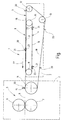
- the figure shows the invention using an exemplary embodiment.
- the leading edge stop device 1 a machine frame 2 on which a Front edge stop strand 3 and a panel push strand 4 are arranged.
- the two runs 3 and 4 exist preferably each of several at a distance from each other lying circumferential straps or chains, so that they can be manipulated across the breadth of Metal sheets, not shown, extend.
- the figure also shows a roller coating unit 5 one Sheet metal painting machine.
- the roller coating unit 5 has one Painting cylinder 6 and an impression cylinder 7 on.
- the arrangement is such that the Leading edge stop device 1 on its transport level 8 sheet metal sheets transported horizontally in the splitting plane 9 between painting cylinder 6 and impression cylinder 7 a perfect fit, which means correct aligned, leads to a register-accurate painting takes place in the rolling mill 5.
- the table drawer 4 is over a first deflection wheel 10 and guided over a second deflection wheel 11.
- the leading edge stop strand 3 has two deflection wheels 12 and 13 and is also around a feed drum 14 guided around, the at least one contact mark 15 having.
- the running strands 16 and 17 of the leading edge stop strand 3 or the table pushing strand 4 are in the transport plane 8.
- the returning runs 18 and 19 are below the Transport level 8.
- the whiteboard is along the transport plane 8 in the transport direction 22 out until the front edge of the Sheet against the lay mark 15 of the lay drum 14 occurs. Only now do you leave the leading edge stops 20 the front edge of the sheet, so that a highly precise handover to the feed drum 14 takes place. This makes it possible for the Feed drum 14 from now by means of further not shown means of transport the precise aligned sheet in the gap between the Painting cylinder 6 and impression cylinder 7 exactly is introduced in a defined position.
- a high cycle rate even with large sheet metal formats ensure follow in the transport plane 8 board drawers 21 assigned to a metal sheet are, with only a small distance leading edge stops 20, which are assigned to a follow-up table.
Landscapes
- Collation Of Sheets And Webs (AREA)
- Registering Or Overturning Sheets (AREA)
- Pile Receivers (AREA)
- Feeding Of Articles By Means Other Than Belts Or Rollers (AREA)
Abstract
Description
Claims (4)
- Vorderkantenanschlagvorrichtung einer Blech-Druckmaschine oder Blech-Lackiermaschine, mit die jeweilige Hinterkante von zu bearbeitenden Blechtafeln beaufschlagenden Tafelschüben, die jeweilige Vorderkante der Blechtafeln beaufschlagenden Vorderkantenanschlägen und eine Anlegetrommel, die mindestens eine Anlegemarke für die Vorderkante der jeweiligen Blechtafel aufweist, dadurch gekennzeichnet, dass die Vorderkantenanschläge (20) die Vorderkante der jeweiligen Blechtafel bis zur Übergabe an die Anlegemarke (15) lückenlos führen.
- Vorderkantenanschlagvorrichtung nach Anspruch 1, dadurch gekennzeichnet, dass die Tafelschübe (21) an einem umlaufenden Tafelschubtrum (4) angeordnet sind.
- Vorderkantenanschlagvorrichtung nach einem der vorhergehenden Ansprüche, dadurch gekennzeichnet, dass die Vorderkantenanschläge (20) an einem umlaufend Vorderkantenanschlagtrum (3) angeordnet sind.
- Vorderkantenanschlagvorrichtung nach einem der vorhergehenden Ansprüche, dadurch gekennzeichnet, dass das Vorderkantenanschlagtrum (3) um die Anlegetrommel (14) herumgeführt ist.
Applications Claiming Priority (2)
| Application Number | Priority Date | Filing Date | Title |
|---|---|---|---|
| DE20000247U | 2000-01-12 | ||
| DE20000247U DE20000247U1 (de) | 2000-01-12 | 2000-01-12 | Vorderkantenanschlagvorrichtung |
Publications (3)
| Publication Number | Publication Date |
|---|---|
| EP1116679A2 true EP1116679A2 (de) | 2001-07-18 |
| EP1116679A3 EP1116679A3 (de) | 2002-12-11 |
| EP1116679B1 EP1116679B1 (de) | 2004-10-13 |
Family
ID=7935659
Family Applications (1)
| Application Number | Title | Priority Date | Filing Date |
|---|---|---|---|
| EP01100410A Expired - Lifetime EP1116679B1 (de) | 2000-01-12 | 2001-01-08 | Vorderkantenanschlagvorrichtung |
Country Status (3)
| Country | Link |
|---|---|
| EP (1) | EP1116679B1 (de) |
| DE (2) | DE20000247U1 (de) |
| ES (1) | ES2228666T3 (de) |
Cited By (2)
| Publication number | Priority date | Publication date | Assignee | Title |
|---|---|---|---|---|
| WO2003066490A3 (de) * | 2002-02-09 | 2003-12-31 | Dieter Klepser | Transportsystem |
| WO2014005812A1 (de) | 2012-07-06 | 2014-01-09 | Kba-Metalprint Gmbh | Fördervorrichtung und verfahren zum fördern von bedruckstoffbogen mit nachgiebigem vorschub |
Families Citing this family (2)
| Publication number | Priority date | Publication date | Assignee | Title |
|---|---|---|---|---|
| DE102005037128B4 (de) * | 2005-08-06 | 2009-04-23 | LTG Mailänder GmbH & Co. KG | Transportsystem einer Blechdruck- oder Blechlackiermaschine |
| DE102007031115B4 (de) * | 2007-06-28 | 2009-04-23 | Kba-Metalprint Gmbh | Vorrichtung zum positionsgenauen Zuführen von tafelförmigen Gütern sowie entsprechendes Verfahren |
Family Cites Families (6)
| Publication number | Priority date | Publication date | Assignee | Title |
|---|---|---|---|---|
| US2811355A (en) * | 1954-12-10 | 1957-10-29 | American Can Co | Feed finger mechanism for sheet feeding and gauging apparatus |
| US4090703A (en) * | 1977-02-07 | 1978-05-23 | Gulf & Western Manufacturing Company | Feeding apparatus for sheet material |
| US4398629A (en) * | 1980-10-20 | 1983-08-16 | Kaiser Steel Corporation | Plate latch and guide system |
| US4508210A (en) * | 1982-02-13 | 1985-04-02 | E.C.H. Will (Gmbh & Co.) | Apparatus for transporting paper stacks or the like |
| JPS59190105A (ja) * | 1983-04-13 | 1984-10-27 | Toppan Printing Co Ltd | 物品搬送装置の物品幅変換装置 |
| JPH0826437A (ja) * | 1994-07-11 | 1996-01-30 | Fuji Photo Film Co Ltd | ワーク移送方法及び移送装置 |
-
2000
- 2000-01-12 DE DE20000247U patent/DE20000247U1/de not_active Expired - Lifetime
-
2001
- 2001-01-08 DE DE2001504054 patent/DE50104054D1/de not_active Expired - Lifetime
- 2001-01-08 ES ES01100410T patent/ES2228666T3/es not_active Expired - Lifetime
- 2001-01-08 EP EP01100410A patent/EP1116679B1/de not_active Expired - Lifetime
Cited By (5)
| Publication number | Priority date | Publication date | Assignee | Title |
|---|---|---|---|---|
| WO2003066490A3 (de) * | 2002-02-09 | 2003-12-31 | Dieter Klepser | Transportsystem |
| WO2014005812A1 (de) | 2012-07-06 | 2014-01-09 | Kba-Metalprint Gmbh | Fördervorrichtung und verfahren zum fördern von bedruckstoffbogen mit nachgiebigem vorschub |
| DE102012211784A1 (de) * | 2012-07-06 | 2014-01-09 | Kba-Metalprint Gmbh | Fördervorrichtung und ein Verfahren zum Fördern von Bedruckstoffbogen |
| CN104487250A (zh) * | 2012-07-06 | 2015-04-01 | Kba金属印刷有限公司 | 用于以易曲式进给来传送单张承印材料的传送设备和方法 |
| CN104487250B (zh) * | 2012-07-06 | 2016-03-16 | Kba金属印刷有限公司 | 用于以易曲式进给来传送单张承印材料的传送设备和方法 |
Also Published As
| Publication number | Publication date |
|---|---|
| EP1116679B1 (de) | 2004-10-13 |
| DE20000247U1 (de) | 2000-03-02 |
| DE50104054D1 (de) | 2004-11-18 |
| ES2228666T3 (es) | 2005-04-16 |
| EP1116679A3 (de) | 2002-12-11 |
Similar Documents
| Publication | Publication Date | Title |
|---|---|---|
| DE2404323C3 (de) | Zuführungsvorrichtung für Platten oder Folien | |
| EP2008956A2 (de) | Vorrichtung zum positionsgenauen Zuführen von tafelförmigen Gütern sowie entsprechendes Verfahren | |
| DE2164056A1 (de) | Maschine zum Schneiden und Falten von Plänen od.dgl. auf ein vorbestimmtes Format und für ähnliche Zwecke | |
| DE8014325U1 (de) | Maschine zum rillen von platten, insbesondere fuer gedruckte schaltungen | |
| DE3028929C2 (de) | ||
| DE3332992A1 (de) | Drucker mit mosaikdruckkoepfen | |
| CH660577A5 (de) | Geraet zum handhaben von flaechigen materialstuecken und schneidemaschine mit einem solchen geraet. | |
| EP1116679B1 (de) | Vorderkantenanschlagvorrichtung | |
| EP1472164B3 (de) | Transportsystem | |
| DE3039541C2 (de) | ||
| DE3030489A1 (de) | Vorrichtung zur ausgabe von papierblaettern | |
| DE1115500B (de) | Transporteinrichtung fuer kartenfoermige Aufzeichnungstraeger, insbesondere Lochkarten | |
| DE2655098B2 (de) | Belegzuführvorrichtung | |
| DE3212199C2 (de) | ||
| DE2712677A1 (de) | Transportvorrichtung fuer gegenstaende, insbesondere blattlagen o.dgl. | |
| DE1233244B (de) | Vorrichtung zum rotierenden Bearbeiten kontinuierlich oder intermittierend gefoerderter Bahnen | |
| DE944925C (de) | Vorrichtung zum Ausrichten von Blechtafeln an Lackiermaschinen | |
| DE2457070C3 (de) | Vorrichtung zum seitlichen Ausrichten von Bogen | |
| DE2735932A1 (de) | Sperrvorrichtung fuer ein blattbehandlungsgeraet | |
| EP0000366A1 (de) | Blattzufuhrvorrichtung | |
| DE1216329B (de) | Zufuehrungsvorrichtung zum vereinzelten Zufuehren von Blaettern zu einer Bogen verarbeitenden Maschine | |
| DE60202945T2 (de) | Vorrichtung zum ausrichten von in einem schuppenstrom bewegten bogen | |
| EP1110894A2 (de) | Verfahren und Vorrichtung zum Falzen von Materialbogen | |
| EP1671908B1 (de) | Einrichtung zur Beschickung einer Verarbeitungsvorrichtung mit in einem Förderstrom transportierten Druckprodukten | |
| DE2612092C2 (de) | Verfahren und Vorrichtung zum automatischen Aufbringen eines Klebebandes auf zumindest eine Randzone einer Schaltungsplatte |
Legal Events
| Date | Code | Title | Description |
|---|---|---|---|
| PUAI | Public reference made under article 153(3) epc to a published international application that has entered the european phase |
Free format text: ORIGINAL CODE: 0009012 |
|
| AK | Designated contracting states |
Kind code of ref document: A2 Designated state(s): AT BE CH CY DE DK ES FI FR GB GR IE IT LI LU MC NL PT SE TR |
|
| AX | Request for extension of the european patent |
Free format text: AL;LT;LV;MK;RO;SI |
|
| PUAL | Search report despatched |
Free format text: ORIGINAL CODE: 0009013 |
|
| AK | Designated contracting states |
Kind code of ref document: A3 Designated state(s): AT BE CH CY DE DK ES FI FR GB GR IE IT LI LU MC NL PT SE TR |
|
| AX | Request for extension of the european patent |
Free format text: AL;LT;LV;MK;RO;SI |
|
| 17P | Request for examination filed |
Effective date: 20030611 |
|
| AKX | Designation fees paid |
Designated state(s): DE ES GB IT |
|
| GRAP | Despatch of communication of intention to grant a patent |
Free format text: ORIGINAL CODE: EPIDOSNIGR1 |
|
| GRAS | Grant fee paid |
Free format text: ORIGINAL CODE: EPIDOSNIGR3 |
|
| GRAA | (expected) grant |
Free format text: ORIGINAL CODE: 0009210 |
|
| AK | Designated contracting states |
Kind code of ref document: B1 Designated state(s): DE ES GB IT |
|
| REG | Reference to a national code |
Ref country code: GB Ref legal event code: FG4D Free format text: NOT ENGLISH |
|
| REG | Reference to a national code |
Ref country code: IE Ref legal event code: FG4D Free format text: GERMAN |
|
| REF | Corresponds to: |
Ref document number: 50104054 Country of ref document: DE Date of ref document: 20041118 Kind code of ref document: P |
|
| GBT | Gb: translation of ep patent filed (gb section 77(6)(a)/1977) |
Effective date: 20050124 |
|
| REG | Reference to a national code |
Ref country code: ES Ref legal event code: FG2A Ref document number: 2228666 Country of ref document: ES Kind code of ref document: T3 |
|
| REG | Reference to a national code |
Ref country code: IE Ref legal event code: FD4D |
|
| PLBE | No opposition filed within time limit |
Free format text: ORIGINAL CODE: 0009261 |
|
| STAA | Information on the status of an ep patent application or granted ep patent |
Free format text: STATUS: NO OPPOSITION FILED WITHIN TIME LIMIT |
|
| 26N | No opposition filed |
Effective date: 20050714 |
|
| REG | Reference to a national code |
Ref country code: DE Ref legal event code: R082 Ref document number: 50104054 Country of ref document: DE |
|
| REG | Reference to a national code |
Ref country code: GB Ref legal event code: 732E Free format text: REGISTERED BETWEEN 20120315 AND 20120321 |
|
| REG | Reference to a national code |
Ref country code: DE Ref legal event code: R081 Ref document number: 50104054 Country of ref document: DE Owner name: KBA-METALPRINT GMBH, DE Free format text: FORMER OWNER: LTG MAILAENDER GMBH & CO. KG, 70435 STUTTGART, DE Effective date: 20120328 |
|
| REG | Reference to a national code |
Ref country code: ES Ref legal event code: PC2A Owner name: KBA-METALPRINT GMBH Effective date: 20120510 |
|
| PGFP | Annual fee paid to national office [announced via postgrant information from national office to epo] |
Ref country code: IT Payment date: 20140124 Year of fee payment: 14 |
|
| PGFP | Annual fee paid to national office [announced via postgrant information from national office to epo] |
Ref country code: GB Payment date: 20140123 Year of fee payment: 14 |
|
| GBPC | Gb: european patent ceased through non-payment of renewal fee |
Effective date: 20150108 |
|
| PG25 | Lapsed in a contracting state [announced via postgrant information from national office to epo] |
Ref country code: GB Free format text: LAPSE BECAUSE OF NON-PAYMENT OF DUE FEES Effective date: 20150108 |
|
| PG25 | Lapsed in a contracting state [announced via postgrant information from national office to epo] |
Ref country code: IT Free format text: LAPSE BECAUSE OF NON-PAYMENT OF DUE FEES Effective date: 20150108 |
|
| PGFP | Annual fee paid to national office [announced via postgrant information from national office to epo] |
Ref country code: ES Payment date: 20190214 Year of fee payment: 19 Ref country code: DE Payment date: 20190304 Year of fee payment: 19 |
|
| REG | Reference to a national code |
Ref country code: DE Ref legal event code: R119 Ref document number: 50104054 Country of ref document: DE |
|
| PG25 | Lapsed in a contracting state [announced via postgrant information from national office to epo] |
Ref country code: DE Free format text: LAPSE BECAUSE OF NON-PAYMENT OF DUE FEES Effective date: 20200801 |
|
| REG | Reference to a national code |
Ref country code: ES Ref legal event code: FD2A Effective date: 20210602 |
|
| PG25 | Lapsed in a contracting state [announced via postgrant information from national office to epo] |
Ref country code: ES Free format text: LAPSE BECAUSE OF NON-PAYMENT OF DUE FEES Effective date: 20200109 |