EP1116679A2 - Front-edge stop device - Google Patents
Front-edge stop device Download PDFInfo
- Publication number
- EP1116679A2 EP1116679A2 EP01100410A EP01100410A EP1116679A2 EP 1116679 A2 EP1116679 A2 EP 1116679A2 EP 01100410 A EP01100410 A EP 01100410A EP 01100410 A EP01100410 A EP 01100410A EP 1116679 A2 EP1116679 A2 EP 1116679A2
- Authority
- EP
- European Patent Office
- Prior art keywords
- leading edge
- sheet
- metal
- stops
- front edge
- Prior art date
- Legal status (The legal status is an assumption and is not a legal conclusion. Google has not performed a legal analysis and makes no representation as to the accuracy of the status listed.)
- Granted
Links
Images
Classifications
-
- B—PERFORMING OPERATIONS; TRANSPORTING
- B65—CONVEYING; PACKING; STORING; HANDLING THIN OR FILAMENTARY MATERIAL
- B65H—HANDLING THIN OR FILAMENTARY MATERIAL, e.g. SHEETS, WEBS, CABLES
- B65H9/00—Registering, e.g. orientating, articles; Devices therefor
- B65H9/10—Pusher and like movable registers; Pusher or gripper devices which move articles into registered position
- B65H9/101—Pusher and like movable registers; Pusher or gripper devices which move articles into registered position acting on the edge of the article
-
- B—PERFORMING OPERATIONS; TRANSPORTING
- B65—CONVEYING; PACKING; STORING; HANDLING THIN OR FILAMENTARY MATERIAL
- B65H—HANDLING THIN OR FILAMENTARY MATERIAL, e.g. SHEETS, WEBS, CABLES
- B65H11/00—Feed tables
- B65H11/007—Feed tables with front stop arrangements
-
- B—PERFORMING OPERATIONS; TRANSPORTING
- B65—CONVEYING; PACKING; STORING; HANDLING THIN OR FILAMENTARY MATERIAL
- B65H—HANDLING THIN OR FILAMENTARY MATERIAL, e.g. SHEETS, WEBS, CABLES
- B65H2404/00—Parts for transporting or guiding the handled material
- B65H2404/20—Belts
- B65H2404/23—Belts with auxiliary handling means
- B65H2404/232—Blade, plate, finger
-
- B—PERFORMING OPERATIONS; TRANSPORTING
- B65—CONVEYING; PACKING; STORING; HANDLING THIN OR FILAMENTARY MATERIAL
- B65H—HANDLING THIN OR FILAMENTARY MATERIAL, e.g. SHEETS, WEBS, CABLES
- B65H2701/00—Handled material; Storage means
- B65H2701/10—Handled articles or webs
- B65H2701/17—Nature of material
- B65H2701/173—Metal
Definitions
- the invention relates to a leading edge stop device a sheet metal printing machine or sheet metal coating machine, with the respective rear edge of table drawers acting on sheet metal, the respective front edge of the metal sheets leading edge stops and a feed drum that has at least one feed mark for the front edge of the respective metal sheet.
- the contact marks are preferably as gripper marks educated.
- the tablet is in the gripper marks using all-round, spring-loaded table drawers from behind, i.e. at the rear edge of the sheet edge attacking support stops, pushed.
- the table drawers run a little faster than the board that transported by an appropriate feed device becomes. This way the table drawers get the Metal sheet.
- the table drawers are on a revolving Trum attached, so that the mentioned catching up after the table drawers appear from the returning strand strand takes place. It can happen occasionally come to bounce, that is, the respective one Sheet metal is going forward uncontrollably encountered.
- leading edge stop system are both table drawers for the rear edges of the boards as well as stop lugs for the front edges of the plates provided.
- the metal sheets are between the stop lugs and the table drawers added, with that of the leading edge of each Table assigned stop tabs in the direction of the table seen diving in front of the feed drum, so that the board against the lay marks of the lay drum be pushed using the table drawers.
- This known device does not always ensure that the sheet of metal fits perfectly for running in is provided in the rolling mill.
- the invention is therefore based on the object Specify leading edge stop device that works with high precision and the metal sheets fit perfectly provides.
- this object is achieved by that the leading edge stops the leading edge of the each sheet of metal until delivery to the landing mark leads seamlessly. Hence the leading edge of the respective metal sheet not at a great distance in front of the landing mark or landing marks the feed drum released, but by means of the front edge stops until they are reached of the landing mark / landing marks.
- This is a high-precision, precisely fitting sheet metal sheet ensured without causing bouncing effects or troubled state of the tablet is coming.
- sheet metal is therefore highly precise the landing mark or the landing marks fed to the feed drum and can therefore fit perfectly geared towards further processing, for example painting in the subsequent roller coating plant, be fed.
- the subject of the invention is Provide the feed drum with at least one feed mark.
- This can preferably be designed as a gripper mark his.
- the sheet is therefore exact and in defined position in the gripper mark. Improper feeding or even spreading the sheet of metal on the gripper mark, like this can occur with known devices, is safely prevented by the subject of the invention.
- the table drawers arranged on a circumferential table drawer are.
- leading edge stops arranged on a circumferential leading edge stop strand are.
- leading edge stop strand is guided around the feed drum. This makes it particularly simple and convenient Construction ensures that the leading edge stops the leading edge of each Sheet of metal until delivery to the landing mark leads.
- the aforementioned "gapless" leadership means that there are no long release times The front edge of the metal sheet is there until it turns on creates the landing mark, but that either the The leading edge has already reached the landing mark before the leading edge stops leave the leading edge, that the leading edge is the landing mark in the Moment reached when the leading edge stops the Leaving leading edge or that just a very short one There is a time span during which the leading edge stops leave the front edge of the sheet have before the leading edge against the landing mark occurs. All three possibilities are according to the invention includes.
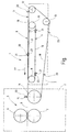
- the figure shows the invention using an exemplary embodiment.
- the leading edge stop device 1 a machine frame 2 on which a Front edge stop strand 3 and a panel push strand 4 are arranged.
- the two runs 3 and 4 exist preferably each of several at a distance from each other lying circumferential straps or chains, so that they can be manipulated across the breadth of Metal sheets, not shown, extend.
- the figure also shows a roller coating unit 5 one Sheet metal painting machine.
- the roller coating unit 5 has one Painting cylinder 6 and an impression cylinder 7 on.
- the arrangement is such that the Leading edge stop device 1 on its transport level 8 sheet metal sheets transported horizontally in the splitting plane 9 between painting cylinder 6 and impression cylinder 7 a perfect fit, which means correct aligned, leads to a register-accurate painting takes place in the rolling mill 5.
- the table drawer 4 is over a first deflection wheel 10 and guided over a second deflection wheel 11.
- the leading edge stop strand 3 has two deflection wheels 12 and 13 and is also around a feed drum 14 guided around, the at least one contact mark 15 having.
- the running strands 16 and 17 of the leading edge stop strand 3 or the table pushing strand 4 are in the transport plane 8.
- the returning runs 18 and 19 are below the Transport level 8.
- the whiteboard is along the transport plane 8 in the transport direction 22 out until the front edge of the Sheet against the lay mark 15 of the lay drum 14 occurs. Only now do you leave the leading edge stops 20 the front edge of the sheet, so that a highly precise handover to the feed drum 14 takes place. This makes it possible for the Feed drum 14 from now by means of further not shown means of transport the precise aligned sheet in the gap between the Painting cylinder 6 and impression cylinder 7 exactly is introduced in a defined position.
- a high cycle rate even with large sheet metal formats ensure follow in the transport plane 8 board drawers 21 assigned to a metal sheet are, with only a small distance leading edge stops 20, which are assigned to a follow-up table.
Abstract
Description
Die Erfindung betrifft eine Vorderkantenanschlagvorrichtung einer Blech-Druckmaschine oder Blech-Lackiermaschine, mit die jeweilige Hinterkante von zu bearbeitenden Blechtafeln beaufschlagenden Tafelschüben, die jeweilige Vorderkante der Blechtafeln beaufschlagenden Vorderkantenanschlägen und eine Anlegetrommel, die mindestens eine Anlegemarke für die Vorderkante der jeweiligen Blechtafel aufweist.The invention relates to a leading edge stop device a sheet metal printing machine or sheet metal coating machine, with the respective rear edge of table drawers acting on sheet metal, the respective front edge of the metal sheets leading edge stops and a feed drum that has at least one feed mark for the front edge of the respective metal sheet.
Von auf dem Markt befindlichen Lackiermaschinen, die dem Lackieren von Blechtafeln dienen, wird die möglichst passgenaue Bereitstellung einer in das Walzlackwerk dieser Maschine einlaufenden Blechtafel durch vorgelagertes Anlegen der Tafelvorderkante an Anlegemarken einer Anlegetrommel erreicht. Die Anlegemarken sind vorzugsweise als Greifermarken ausgebildet. In die Greifermarken wird die Tafel mittels umlaufenden, gefederten Tafelschüben von hinten, also an der Hinterkante der Blechkante angreifenden Stützanschlägen, geschoben. Die Tafelschübe laufen etwas schneller als die Tafel, die von einer entsprechenden Zuführeinrichtung transportiert wird. Hierdurch holen die Tafelschübe die Blechtafel ein. Die Tafelschübe sind an einem umlaufenden Trum befestigt, so dass das erwähnte Einholen nach dem Auftauchen der Tafelschübe aus dem rücklaufenden Trumstrang erfolgt. Dabei kann es gelegentlich zum Prellen kommen, das heißt, die jeweilige Blechtafel wird unkontrolliert nach vorn gestoßen.Of painting machines on the market, which are used for painting metal sheets, the Provision of one in the Roll coating machine of this machine incoming sheet metal by placing the front edge of the board in front reached on the contact marks of a contact drum. The contact marks are preferably as gripper marks educated. The tablet is in the gripper marks using all-round, spring-loaded table drawers from behind, i.e. at the rear edge of the sheet edge attacking support stops, pushed. The table drawers run a little faster than the board that transported by an appropriate feed device becomes. This way the table drawers get the Metal sheet. The table drawers are on a revolving Trum attached, so that the mentioned catching up after the table drawers appear from the returning strand strand takes place. It can happen occasionally come to bounce, that is, the respective one Sheet metal is going forward uncontrollably encountered.
Um das unkontrollierte Nach-Vorne-Stoßen einer Blechtafel zu vermeiden, ist nach einem anderen bekannten Vorderkantenanschlagsystem vorgesehen, dass ein umlaufendes Trum mit Anschlagnasen ausgebildet ist. Die Umlaufgeschwindigkeit dieses mit Anschlagnasen versehenen Trums ist etwas geringer als die Tafelgeschwindigkeit, so dass die Tafeln mit ihren Vorderkanten auf die Anschlagnasen auflaufen und die Transportriemen der Zuführeinrichtung dann leicht durchrutschen.About the uncontrolled thrusting forward Avoiding sheet metal is known according to another Leading edge stop system provided that a circumferential run with stop lugs formed is. The rotational speed of this with stop lugs provided strand is slightly less than that Board speed, so the boards with their Run the front edges onto the stop lugs and then the conveyor belts of the feed device slip easily.
Nach einem weiteren bekannten Vorderkantenanschlagsystem sind sowohl Tafelschübe für die Hinterkanten der Tafeln als auch Anschlagnasen für die Vorderkanten der Tafeln vorgesehen. Die Blechtafeln werden zwischen den Anschlagnasen und den Tafelschüben aufgenommen, wobei die der Vorderkante der jeweiligen Tafel zugeordneten Anschlagnasen in Tafellaufrichtung gesehen vor der Anlegetrommel abtauchen, so dass die Tafel gegen die Anlegemarken der Anlegetrommel mittels der Tafelschübe geschoben werden. Diese bekannte Vorrichtung stellt nicht immer sicher, dass die Blechtafel passgenau für das Einlaufen in das Walzlackwerk bereitgestellt wird.According to another known leading edge stop system are both table drawers for the rear edges of the boards as well as stop lugs for the front edges of the plates provided. The metal sheets are between the stop lugs and the table drawers added, with that of the leading edge of each Table assigned stop tabs in the direction of the table seen diving in front of the feed drum, so that the board against the lay marks of the lay drum be pushed using the table drawers. This known device does not always ensure that the sheet of metal fits perfectly for running in is provided in the rolling mill.
Der Erfindung liegt daher die Aufgabe zugrunde, eine Vorderkantenanschlagvorrichtung anzugeben, die hochpräzise arbeitet und die Blechtafeln passgenau bereitstellt. The invention is therefore based on the object Specify leading edge stop device that works with high precision and the metal sheets fit perfectly provides.
Diese Aufgabe wird erfindungsgemäß dadurch gelöst, dass die Vorderkantenanschläge die Vorderkante der jeweiligen Blechtafel bis zur Übergabe an die Anlegemarke lückenlos führt. Mithin wird die Vorderkante der jeweiligen Blechtafel nicht mit großem Abstand vor der Anlegemarke beziehungsweise Anlegemarken der Anlegetrommel freigegeben, sondern mittels der Vorderkantenanschläge bis zum Erreichen der Anlegemarke/Anlegemarken geführt. Hierdurch ist ein hochpräzises, passgenaues Anlegen der Blechtafel sichergestellt, ohne dass es zu Prelleffekten oder unruhigen Zuständen der Tafel kommt. Die Blechtafel wird also erfindungsgemäß hochpräzise der Anlegemarke beziehungsweise den Anlegemarken der Anlegetrommel zugeführt und kann daher passgenau ausgerichtet der Weiterverarbeitung, beispielsweise dem Lackieren im nachfolgenden Walzlackwerk, zugeführt werden. Beim Erfindungsgegenstand ist die Anlegetrommel mindestens mit einer Anlegemarke versehen. Diese kann bevorzugt als Greifermarke ausgebildet sein. Die Blechtafel wird daher exakt und in definierter Lage in die Greifermarke eingeführt. Ein nicht passgenaues Zuführen oder sogar ein Aufreiten der Blechtafel auf die Greifermarke, wie dies bei bekannten Vorrichtungen vorkommen kann, ist durch den Gegenstand der Erfindung sicher verhindert.According to the invention, this object is achieved by that the leading edge stops the leading edge of the each sheet of metal until delivery to the landing mark leads seamlessly. Hence the leading edge of the respective metal sheet not at a great distance in front of the landing mark or landing marks the feed drum released, but by means of the front edge stops until they are reached of the landing mark / landing marks. This is a high-precision, precisely fitting sheet metal sheet ensured without causing bouncing effects or troubled state of the tablet is coming. The According to the invention, sheet metal is therefore highly precise the landing mark or the landing marks fed to the feed drum and can therefore fit perfectly geared towards further processing, for example painting in the subsequent roller coating plant, be fed. The subject of the invention is Provide the feed drum with at least one feed mark. This can preferably be designed as a gripper mark his. The sheet is therefore exact and in defined position in the gripper mark. Improper feeding or even spreading the sheet of metal on the gripper mark, like this can occur with known devices, is safely prevented by the subject of the invention.
Vorzugsweise kann vorgesehen sein, dass die Tafelschübe an einem umlaufenden Tafelschubtrum angeordnet sind. It can preferably be provided that the table drawers arranged on a circumferential table drawer are.
Es ist vorteilhaft, wenn die Vorderkantenanschläge an einem umlaufenden Vorderkantenanschlagtrum angeordnet sind.It is advantageous if the leading edge stops arranged on a circumferential leading edge stop strand are.
Besonders bevorzugt ist, wenn das Vorderkantenanschlagtrum um die Anlegetrommel herumgeführt ist. Hierdurch ist in besonders einfacher und zweckmäßiger Konstruktion sichergestellt, dass die Vorderkantenanschläge die Vorderkante der jeweiligen Blechtafel bis zur Übergabe an die Anlegemarke führt. Die vorstehend erwähnte "lückenlose" Führung bedeutet, dass es keine langen Freigabezeiten der Vorderkante der Blechtafel gibt, bis sich diese an die Anlegemarke anlegt, sondern dass entweder die Vorderkante bereits die Anlegemarke erreicht, bevor die Vorderkantenanschläge die Vorderkante verlassen, dass die Vorderkante die Anlegemarke in dem Moment erreicht, wenn die Vorderkantenanschläge die Vorderkante verlassen oder dass nur eine sehr kurze Zeitspanne vorhanden ist, während der die Vorderkantenanschläge die Vorderkante der Blechtafel verlassen haben, bevor die Vorderkante gegen die Anlegemarke tritt. Alle drei Möglichkeiten sind erfindungsgemäß umfasst.It is particularly preferred if the leading edge stop strand is guided around the feed drum. This makes it particularly simple and convenient Construction ensures that the leading edge stops the leading edge of each Sheet of metal until delivery to the landing mark leads. The aforementioned "gapless" leadership means that there are no long release times The front edge of the metal sheet is there until it turns on creates the landing mark, but that either the The leading edge has already reached the landing mark before the leading edge stops leave the leading edge, that the leading edge is the landing mark in the Moment reached when the leading edge stops the Leaving leading edge or that just a very short one There is a time span during which the leading edge stops leave the front edge of the sheet have before the leading edge against the landing mark occurs. All three possibilities are according to the invention includes.
Die Figur zeigt die Erfindung anhand eines Ausführungsbeispiels.The figure shows the invention using an exemplary embodiment.
Gemäß der Figur weist die Vorderkantenanschlagvorrichtung
1 ein Maschinengestell 2 auf, an dem ein
Vorderkantenanschlagtrum 3 und ein Tafelschubtrum 4
angeordnet sind. Die beiden Trums 3 und 4 bestehen
vorzugsweise jeweils aus mehreren mit Abstand zueinander
liegenden umlaufenden Riemen oder Ketten,
so dass sie sich über die Breite von zu manipulierenden,
nicht dargestellten Blechtafeln erstrecken.
Die Figur zeigt ferner ein Walzlackwerk 5 einer
Blech-Lackiermaschine. Das Walzlackwerk 5 weist einen
Lackierzylinder 6 und einen Gegendruckzylinder
7 auf. Die Anordnung ist derart getroffen, dass die
Vorderkantenanschlagvorrichtung 1 auf ihrer Transportebene
8 liegend transportierte Blechtafeln in
die Spaltebene 9 zwischen Lackierzylinder 6 und Gegendruckzylinder
7 passgenau, das heißt korrekt
ausgerichtet, führt, so dass ein passergenaues Lackieren
im Walzlackwerk 5 erfolgt.According to the figure, the leading edge stop device
1 a
Das Tafelschubtrum 4 ist über ein erstes Umlenkrad
10 und über ein zweites Umlenkrad 11 geführt. Das
Vorderkantenanschlagtrum 3 weist zwei Umlenkräder
12 und 13 auf und ist ferner um eine Anlegetrommel
14 herumgeführt, die mindestens eine Anlegemarke 15
aufweist. Die hinlaufenden Trums 16 und 17 des Vorderkantenanschlagtrums
3 beziehungsweise des Tafelschubtrums
4 liegen in der Transportebene 8. Die
rücklaufenden Trums 18 und 19 liegen unterhalb der
Transportebene 8.The table drawer 4 is over a
Gleichmäßig voneinander beabstandet sind am Vorderkantenanschlagtrum
3 Vorderkantenanschläge 20 befestigt.
Ebenfalls mit äquidistanten Abständen sind
am Tafelschubtrum 4 Tafelschübe 21 befestigt, die
-bei Lage in der Transportebene 8- entgegen der
Transportrichtung (Pfeil 22) mittels Federn 23
nachgeben können. Die Konstruktion ist derart gestaltet,
dass im Betrieb eine mittels nicht dargestellter
Fördermittel von einem Blechtafelstapel
abgehobene und mittels einer Fördereinrichtung zugeführte
Blechtafel mit ihrer Vorderkante gegen die
Vorderkantenanschläge 20 tritt. Im Zuge der Weiterförderung
der Blechtafel in ihrer in der Transportebene
8 liegenden Position treten gegen die Hinterkante
der Blechtafel die Tafelschübe 21. Die Blechtafel
ist zwischen den Vorderkantenanschlägen 20
und Tafelschüben 21 mit möglichst geringem Spiel
aufgenommen. Die Aufnahme erfolgt so vorsichtig,
dass Kantenbeschädigungen vermieden sind. Die Tafel
wird entlang der Transportebene 8 in Transportrichtung
22 geführt, solange, bis die Vorderkante der
Blechtafel gegen die Anlegemarke 15 der Anlegetrommel
14 tritt. Erst jetzt verlassen die Vorderkantenanschläge
20 die Vorderkante der Blechtafel, so
dass eine hochpräzise Übergabe an die Anlegetrommel
14 erfolgt. Hierdurch ist es möglich, dass von der
Anlegetrommel 14 aus nunmehr mittels weiterer,
nicht dargestellter Transportmittel die präzise
ausgerichtete Blechtafel in den Spalt zwischen dem
Lackierzylinder 6 und Gegendruckzylinder 7 exakt
lagedefiniert eingeführt wird.Are evenly spaced from each other on the leading
Um eine hohe Taktfolge auch bei großen Blechtafelformaten
sicherzustellen, folgen in der Transportebene
8 Tafelschübe 21, die einer Blechtafel zugeordnet
sind, mit nur geringem Abstand Vorderkantenanschläge
20, die einer Folgetafel zugeordnet sind.A high cycle rate even with large sheet metal formats
ensure follow in the
Aufgrund der erfindungsgemäßen durchgängigen Tafelführung ist ein reproduzierbares passgenaues Anlegen der Blechtafeln möglich.Because of the consistent table guidance according to the invention is a reproducible fitting of the metal sheets possible.
Claims (4)
Applications Claiming Priority (2)
| Application Number | Priority Date | Filing Date | Title |
|---|---|---|---|
| DE20000247U | 2000-01-12 | ||
| DE20000247U DE20000247U1 (en) | 2000-01-12 | 2000-01-12 | Leading edge stop device |
Publications (3)
| Publication Number | Publication Date |
|---|---|
| EP1116679A2 true EP1116679A2 (en) | 2001-07-18 |
| EP1116679A3 EP1116679A3 (en) | 2002-12-11 |
| EP1116679B1 EP1116679B1 (en) | 2004-10-13 |
Family
ID=7935659
Family Applications (1)
| Application Number | Title | Priority Date | Filing Date |
|---|---|---|---|
| EP01100410A Expired - Lifetime EP1116679B1 (en) | 2000-01-12 | 2001-01-08 | Front-edge stop device |
Country Status (3)
| Country | Link |
|---|---|
| EP (1) | EP1116679B1 (en) |
| DE (2) | DE20000247U1 (en) |
| ES (1) | ES2228666T3 (en) |
Cited By (2)
| Publication number | Priority date | Publication date | Assignee | Title |
|---|---|---|---|---|
| WO2003066490A2 (en) * | 2002-02-09 | 2003-08-14 | Dieter Klepser | Transport system |
| WO2014005812A1 (en) | 2012-07-06 | 2014-01-09 | Kba-Metalprint Gmbh | Conveying device and method for conveying printed sheets with an elastic advancement |
Families Citing this family (2)
| Publication number | Priority date | Publication date | Assignee | Title |
|---|---|---|---|---|
| DE102005037128B4 (en) * | 2005-08-06 | 2009-04-23 | LTG Mailänder GmbH & Co. KG | Transport system of a sheet metal or sheet metal painting machine |
| DE102007031115B4 (en) * | 2007-06-28 | 2009-04-23 | Kba-Metalprint Gmbh | Device for positionally accurate feeding of tabular goods and corresponding method |
Citations (6)
| Publication number | Priority date | Publication date | Assignee | Title |
|---|---|---|---|---|
| US2811355A (en) * | 1954-12-10 | 1957-10-29 | American Can Co | Feed finger mechanism for sheet feeding and gauging apparatus |
| DE2804759A1 (en) * | 1977-02-07 | 1978-08-10 | Gulf & Western Mfg Co | FEED DEVICE FOR SURFACE MATERIAL, IN PARTICULAR FOR PANELS |
| US4398629A (en) * | 1980-10-20 | 1983-08-16 | Kaiser Steel Corporation | Plate latch and guide system |
| DE3303331A1 (en) * | 1982-02-13 | 1983-08-25 | E.C.H. Will (Gmbh & Co), 2000 Hamburg | Conveying arrangement for feeding loose paper layers in an intermittent manner |
| US4641742A (en) * | 1983-04-13 | 1987-02-10 | Toppan Printing Co., Ltd. | Article transfer apparatus |
| DE19525115A1 (en) * | 1994-07-11 | 1996-01-18 | Fuji Photo Film Co Ltd | Method for transporting workpieces |
-
2000
- 2000-01-12 DE DE20000247U patent/DE20000247U1/en not_active Expired - Lifetime
-
2001
- 2001-01-08 DE DE2001504054 patent/DE50104054D1/en not_active Expired - Lifetime
- 2001-01-08 EP EP01100410A patent/EP1116679B1/en not_active Expired - Lifetime
- 2001-01-08 ES ES01100410T patent/ES2228666T3/en not_active Expired - Lifetime
Patent Citations (6)
| Publication number | Priority date | Publication date | Assignee | Title |
|---|---|---|---|---|
| US2811355A (en) * | 1954-12-10 | 1957-10-29 | American Can Co | Feed finger mechanism for sheet feeding and gauging apparatus |
| DE2804759A1 (en) * | 1977-02-07 | 1978-08-10 | Gulf & Western Mfg Co | FEED DEVICE FOR SURFACE MATERIAL, IN PARTICULAR FOR PANELS |
| US4398629A (en) * | 1980-10-20 | 1983-08-16 | Kaiser Steel Corporation | Plate latch and guide system |
| DE3303331A1 (en) * | 1982-02-13 | 1983-08-25 | E.C.H. Will (Gmbh & Co), 2000 Hamburg | Conveying arrangement for feeding loose paper layers in an intermittent manner |
| US4641742A (en) * | 1983-04-13 | 1987-02-10 | Toppan Printing Co., Ltd. | Article transfer apparatus |
| DE19525115A1 (en) * | 1994-07-11 | 1996-01-18 | Fuji Photo Film Co Ltd | Method for transporting workpieces |
Cited By (6)
| Publication number | Priority date | Publication date | Assignee | Title |
|---|---|---|---|---|
| WO2003066490A2 (en) * | 2002-02-09 | 2003-08-14 | Dieter Klepser | Transport system |
| WO2003066490A3 (en) * | 2002-02-09 | 2003-12-31 | Dieter Klepser | Transport system |
| WO2014005812A1 (en) | 2012-07-06 | 2014-01-09 | Kba-Metalprint Gmbh | Conveying device and method for conveying printed sheets with an elastic advancement |
| DE102012211784A1 (en) * | 2012-07-06 | 2014-01-09 | Kba-Metalprint Gmbh | Conveying device and a method for conveying of printing material sheet |
| CN104487250A (en) * | 2012-07-06 | 2015-04-01 | Kba金属印刷有限公司 | Conveying device and method for conveying printed sheets with an elastic advancement |
| CN104487250B (en) * | 2012-07-06 | 2016-03-16 | Kba金属印刷有限公司 | For transmitting transfer equipment and the method for individual printable fabric with easy musical form feeding |
Also Published As
| Publication number | Publication date |
|---|---|
| EP1116679B1 (en) | 2004-10-13 |
| DE50104054D1 (en) | 2004-11-18 |
| EP1116679A3 (en) | 2002-12-11 |
| DE20000247U1 (en) | 2000-03-02 |
| ES2228666T3 (en) | 2005-04-16 |
Similar Documents
| Publication | Publication Date | Title |
|---|---|---|
| DE2404323C3 (en) | Feeding device for plates or foils | |
| EP2008956A2 (en) | Device for supplying exactly positioned bar-shaped goods and corresponding method | |
| DE2164056A1 (en) | Machine for cutting and folding plans or the like. to a predetermined format and for similar purposes | |
| CH619399A5 (en) | ||
| DE8014325U1 (en) | MACHINE FOR SCRAPING PANELS, ESPECIALLY FOR PRINTED CIRCUITS | |
| DE3028929C2 (en) | ||
| CH660577A5 (en) | DEVICE FOR HANDLING AREA MATERIAL PIECES AND CUTTING MACHINE WITH SUCH A DEVICE. | |
| EP1116679B1 (en) | Front-edge stop device | |
| DE2655098C3 (en) | Document feeder | |
| DE3030489A1 (en) | Automatic banknote dispensing appts. - has slot limiter preventing dispensing more than one note simultaneously using link and roller | |
| DE3039541C2 (en) | ||
| EP1472164B3 (en) | Transport system | |
| DE1115500B (en) | Transport device for card-shaped recording media, especially punch cards | |
| DE3212199C2 (en) | ||
| DE2712677A1 (en) | TRANSPORT DEVICE FOR OBJECTS, IN PARTICULAR LAYERS OF LEAVES OR DGL. | |
| DE1233244B (en) | Device for rotating processing of continuously or intermittently conveyed tracks | |
| DE944925C (en) | Device for aligning sheet metal on painting machines | |
| DE2457070C3 (en) | Device for the lateral alignment of sheets | |
| DE2735932A1 (en) | LOCKING DEVICE FOR A LEAF TREATMENT DEVICE | |
| EP0000366A1 (en) | Sheet feeding device | |
| DE3122585A1 (en) | DEVICE FOR TAKING FILMS, IN PARTICULAR X-RAY FILMS FROM A MAGAZINE | |
| DE1216329B (en) | Feeding device for the individual feeding of sheets to a sheet processing machine | |
| DE60202945T2 (en) | DEVICE FOR ALIGNING ARC MOVED IN A SHOW CURRENT | |
| EP1110894A2 (en) | Method and device for folding sheets of material | |
| EP1671908B1 (en) | Apparatus for supplying a processing device with a transport stream of printing products |
Legal Events
| Date | Code | Title | Description |
|---|---|---|---|
| PUAI | Public reference made under article 153(3) epc to a published international application that has entered the european phase |
Free format text: ORIGINAL CODE: 0009012 |
|
| AK | Designated contracting states |
Kind code of ref document: A2 Designated state(s): AT BE CH CY DE DK ES FI FR GB GR IE IT LI LU MC NL PT SE TR |
|
| AX | Request for extension of the european patent |
Free format text: AL;LT;LV;MK;RO;SI |
|
| PUAL | Search report despatched |
Free format text: ORIGINAL CODE: 0009013 |
|
| AK | Designated contracting states |
Kind code of ref document: A3 Designated state(s): AT BE CH CY DE DK ES FI FR GB GR IE IT LI LU MC NL PT SE TR |
|
| AX | Request for extension of the european patent |
Free format text: AL;LT;LV;MK;RO;SI |
|
| 17P | Request for examination filed |
Effective date: 20030611 |
|
| AKX | Designation fees paid |
Designated state(s): DE ES GB IT |
|
| GRAP | Despatch of communication of intention to grant a patent |
Free format text: ORIGINAL CODE: EPIDOSNIGR1 |
|
| GRAS | Grant fee paid |
Free format text: ORIGINAL CODE: EPIDOSNIGR3 |
|
| GRAA | (expected) grant |
Free format text: ORIGINAL CODE: 0009210 |
|
| AK | Designated contracting states |
Kind code of ref document: B1 Designated state(s): DE ES GB IT |
|
| REG | Reference to a national code |
Ref country code: GB Ref legal event code: FG4D Free format text: NOT ENGLISH |
|
| REG | Reference to a national code |
Ref country code: IE Ref legal event code: FG4D Free format text: GERMAN |
|
| REF | Corresponds to: |
Ref document number: 50104054 Country of ref document: DE Date of ref document: 20041118 Kind code of ref document: P |
|
| GBT | Gb: translation of ep patent filed (gb section 77(6)(a)/1977) |
Effective date: 20050124 |
|
| REG | Reference to a national code |
Ref country code: ES Ref legal event code: FG2A Ref document number: 2228666 Country of ref document: ES Kind code of ref document: T3 |
|
| REG | Reference to a national code |
Ref country code: IE Ref legal event code: FD4D |
|
| PLBE | No opposition filed within time limit |
Free format text: ORIGINAL CODE: 0009261 |
|
| STAA | Information on the status of an ep patent application or granted ep patent |
Free format text: STATUS: NO OPPOSITION FILED WITHIN TIME LIMIT |
|
| 26N | No opposition filed |
Effective date: 20050714 |
|
| REG | Reference to a national code |
Ref country code: DE Ref legal event code: R082 Ref document number: 50104054 Country of ref document: DE |
|
| REG | Reference to a national code |
Ref country code: GB Ref legal event code: 732E Free format text: REGISTERED BETWEEN 20120315 AND 20120321 |
|
| REG | Reference to a national code |
Ref country code: DE Ref legal event code: R081 Ref document number: 50104054 Country of ref document: DE Owner name: KBA-METALPRINT GMBH, DE Free format text: FORMER OWNER: LTG MAILAENDER GMBH & CO. KG, 70435 STUTTGART, DE Effective date: 20120328 |
|
| REG | Reference to a national code |
Ref country code: ES Ref legal event code: PC2A Owner name: KBA-METALPRINT GMBH Effective date: 20120510 |
|
| PGFP | Annual fee paid to national office [announced via postgrant information from national office to epo] |
Ref country code: IT Payment date: 20140124 Year of fee payment: 14 |
|
| PGFP | Annual fee paid to national office [announced via postgrant information from national office to epo] |
Ref country code: GB Payment date: 20140123 Year of fee payment: 14 |
|
| GBPC | Gb: european patent ceased through non-payment of renewal fee |
Effective date: 20150108 |
|
| PG25 | Lapsed in a contracting state [announced via postgrant information from national office to epo] |
Ref country code: GB Free format text: LAPSE BECAUSE OF NON-PAYMENT OF DUE FEES Effective date: 20150108 |
|
| PG25 | Lapsed in a contracting state [announced via postgrant information from national office to epo] |
Ref country code: IT Free format text: LAPSE BECAUSE OF NON-PAYMENT OF DUE FEES Effective date: 20150108 |
|
| PGFP | Annual fee paid to national office [announced via postgrant information from national office to epo] |
Ref country code: ES Payment date: 20190214 Year of fee payment: 19 Ref country code: DE Payment date: 20190304 Year of fee payment: 19 |
|
| REG | Reference to a national code |
Ref country code: DE Ref legal event code: R119 Ref document number: 50104054 Country of ref document: DE |
|
| PG25 | Lapsed in a contracting state [announced via postgrant information from national office to epo] |
Ref country code: DE Free format text: LAPSE BECAUSE OF NON-PAYMENT OF DUE FEES Effective date: 20200801 |
|
| REG | Reference to a national code |
Ref country code: ES Ref legal event code: FD2A Effective date: 20210602 |
|
| PG25 | Lapsed in a contracting state [announced via postgrant information from national office to epo] |
Ref country code: ES Free format text: LAPSE BECAUSE OF NON-PAYMENT OF DUE FEES Effective date: 20200109 |