EP1114705A1 - Dispositif pour aligner et déposer des particules oblongues telles que des copeaux de bois, des fibres de bois ou similaires sur un support déplacé en continu - Google Patents
Dispositif pour aligner et déposer des particules oblongues telles que des copeaux de bois, des fibres de bois ou similaires sur un support déplacé en continu Download PDFInfo
- Publication number
- EP1114705A1 EP1114705A1 EP01107199A EP01107199A EP1114705A1 EP 1114705 A1 EP1114705 A1 EP 1114705A1 EP 01107199 A EP01107199 A EP 01107199A EP 01107199 A EP01107199 A EP 01107199A EP 1114705 A1 EP1114705 A1 EP 1114705A1
- Authority
- EP
- European Patent Office
- Prior art keywords
- continuously moving
- particles
- straightening
- moving support
- base
- Prior art date
- Legal status (The legal status is an assumption and is not a legal conclusion. Google has not performed a legal analysis and makes no representation as to the accuracy of the status listed.)
- Withdrawn
Links
Images

Classifications
-
- B—PERFORMING OPERATIONS; TRANSPORTING
- B27—WORKING OR PRESERVING WOOD OR SIMILAR MATERIAL; NAILING OR STAPLING MACHINES IN GENERAL
- B27N—MANUFACTURE BY DRY PROCESSES OF ARTICLES, WITH OR WITHOUT ORGANIC BINDING AGENTS, MADE FROM PARTICLES OR FIBRES CONSISTING OF WOOD OR OTHER LIGNOCELLULOSIC OR LIKE ORGANIC MATERIAL
- B27N3/00—Manufacture of substantially flat articles, e.g. boards, from particles or fibres
- B27N3/08—Moulding or pressing
- B27N3/10—Moulding of mats
- B27N3/14—Distributing or orienting the particles or fibres
- B27N3/143—Orienting the particles or fibres
-
- B—PERFORMING OPERATIONS; TRANSPORTING
- B27—WORKING OR PRESERVING WOOD OR SIMILAR MATERIAL; NAILING OR STAPLING MACHINES IN GENERAL
- B27N—MANUFACTURE BY DRY PROCESSES OF ARTICLES, WITH OR WITHOUT ORGANIC BINDING AGENTS, MADE FROM PARTICLES OR FIBRES CONSISTING OF WOOD OR OTHER LIGNOCELLULOSIC OR LIKE ORGANIC MATERIAL
- B27N3/00—Manufacture of substantially flat articles, e.g. boards, from particles or fibres
- B27N3/08—Moulding or pressing
- B27N3/10—Moulding of mats
- B27N3/14—Distributing or orienting the particles or fibres
Definitions
- the invention relates to a device for aligning and depositing elongated lignocellulose containing at least one binder and / or cellulose-containing particles such as wood chips, wood fibers or the like on a continuously moving pad to a fleece for the subsequent production of plates containing such a particle Dosing bunker, a unit for transferring the particles an orientation unit above a continuously moving one Underlay is arranged, the distance between the orientation unit and the continuously moving pad is higher than that Top of the fleece to be formed.
- each guide surface protrudes in the same plane
- a plurality of spaced apart projections, their thickness is equal to the thickness of the guide surface.
- These tabs are as regular Quadrilaterals with two parallel edges and one on top, for Border edge parallel top edge and / or as triangles with an overhead Tip trained. What is achieved is that those particles the top edges of two or more moving guide surfaces span first, twisted in an arc and then aligned parallel to each other between the guide surfaces continuously moving pad fall, but there is at least the Risk of clogging and damage to the particles.
- a differently designed device for aligning wooden particles (strands) across the width of a moving pad is from the German Laid-open publication 2,523,515. Belong to this facility a pre-orientation unit that has a plurality of upright ribs also has a drum with attached to its outer circumference Wooden strand orientation guide plates and a catching device, which the wooden strands between an arcuate casing and a plurality of spaces, each through the peripheral surface the drum and a pair of baffle surfaces, so long trapped until released at a predetermined location to be aligned parallel to each other on a moving surface to fall on which they lie across their direction of movement. The throughput and the degree of orientation of the particles are however not satisfactory.
- the invention has for its object an alignment device trained in such a way that the degree of orientation of Particles with high throughput and without damage to the particles can be improved in trouble-free operation.
- the solution task in that the orientation unit in the direction of movement the pad several parallel to each other across the width of the Underlay arranged vertical straightening surfaces with above their upper Has edge protruding projections and each adjacent Straightening surfaces can be driven in the opposite direction, that each straightening surface superimposed movements accordingly their longitudinal extent as well as perpendicular to it.
- Figure 1 shows a dosing hopper 1, which is carried out in a conventional manner can be and next to a bottom conveyor belt and Stripping rollers has a feed unit 2, by means of which the glued lignocellulosic and / or cellulosic elongated particles over pendulum flaps 3 an orientation unit enclosed in a housing 4 provided group of opening rollers 5 are supplied.
- the opening rollers 5 extend across the width of a moving base 10, on which the respective fleece is formed.
- a first group of Opening rollers 5 is counterclockwise and a second group in Driven clockwise so that the supplied via the feed unit 2 Particle material is evenly distributed and accordingly evenly meets a group of fan rollers 7, which below the Group of opening rollers 5 arranged and against the direction of movement the moving pad 10 are driven in rotation.
- Between the opening rollers 5 and the fan rollers 7 are in relation to the Vertical inclined baffles 6 are provided, which ensure that the fan rollers 7 targeted in their upper area where the fans 9 open towards the opening rollers 5, be loaded.
- the fan rollers 7 have a plurality of alignment surfaces 8, which are impermeable to air are executed and such a mutual distance have that only so much particulate matter in a compartment 9 can be that a complete alignment of the elongated particles can be guaranteed.
- the alignment surfaces 8 are designed so that they are the recorded and due to the flat structure transverse to the direction of movement of the base 10 aligned elongated particles only then again from the compartments 9 give up when the fall of the particles between fan roller 7 and moving Base 10 or the base 10 formed on this moving base Fleece is minimized.
- the alignment surfaces 8 are opposite to the direction of rotation of the fan roller 7 curved and / or at least in the region of their free ends angled. Depending on the practical circumstances, can the alignment surfaces are continuously curved, with towards the free end decreasing radius of curvature curved or only in the area the free ends can be curved. Instead of a continuous one Curvature can also be provided, the alignment surfaces 8 especially to fold several times, so that several levels, over kinks interconnected partial surfaces are present, which is a curved Approach the structure like a polygon.
- the orientation unit 4 enclosed by a housing is preferred is adjustable in height with respect to the moving base 10, as indicated by double arrows.
- the axes of each other Identical fan rollers 7 preferably lie in one plane, the one with the moving pad 10 the angle of rise of the on the Base 10 formed nonwoven at least substantially corresponding History.
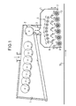
- the embodiment according to FIG. 2 differs from the device according to Figure 1 in that instead of the group of fan rollers 7, a group of straightening surfaces 11 is arranged below the opening rollers 5 is. These straightening surfaces 11 have a mutual relationship with one another Distance that is less than the longitudinal extent of the to be aligned Particles. There are so many in parallel Straightening surfaces 11 provided that coming from the feed unit 2 Particles only over the entire width of the moving surface 10 extending arrangement of straightening surfaces 11 reach the base 10 can.
- the straightening surfaces 11 must ensure that the opening rollers 5 particles oriented so that they do not orientate themselves on the straightening surfaces 11 that they are parallel to the direction of movement of the pad 10 run and get appropriately aligned on this pad 10.
- the straightening surfaces 11 are set in motion on the one hand and others provided on their top with projections 12 so that on the Directional forces corresponding to particles can be exerted.
- the straightening surfaces 11 not only execute a movement parallel to the moving base 10, but that these straightening surfaces 11 always have movement components have perpendicular to this pad 10, because in this way the Alignment effect, i.e. the degree of orientation is significantly improved and thus also the performance of the overall device accordingly is increased.
- the side-by-side straightening surfaces 11, of which the neighboring straightening surfaces 11 are always driven in opposite directions, are hinged at the end to swivel arms 13, and this articulation leads to the straightening surfaces 11 having a rocking movement, ie a movement with horizontal ones and perform vertical motion components.
- the straightening surfaces 11 are provided on their upper side with friction-increasing projections 12.
- projections 12 can be designed in a wave or arc shape but also the shape of triangles, rectangles, trapezoids and the like have, wherein edges of the projections are preferably rounded to to ensure a gentle and damage-free treatment of the particles.
Landscapes
- Life Sciences & Earth Sciences (AREA)
- Engineering & Computer Science (AREA)
- Manufacturing & Machinery (AREA)
- Wood Science & Technology (AREA)
- Forests & Forestry (AREA)
- Dry Formation Of Fiberboard And The Like (AREA)
- Preliminary Treatment Of Fibers (AREA)
- Debarking, Splitting, And Disintegration Of Timber (AREA)
- Feeding Of Articles To Conveyors (AREA)
- Chemical And Physical Treatments For Wood And The Like (AREA)
- Nonwoven Fabrics (AREA)
Applications Claiming Priority (3)
| Application Number | Priority Date | Filing Date | Title |
|---|---|---|---|
| DE29707143U | 1997-04-21 | ||
| DE29707143U DE29707143U1 (de) | 1997-04-21 | 1997-04-21 | Vorrichtung zum Ausrichten und Ablegen von länglichen Teilchen wie Holzspänen, Holzfasern o.dgl. auf einer kontinuierlich bewegten Unterlage |
| EP98922744A EP0977656B1 (fr) | 1997-04-21 | 1998-04-20 | Dispositif pour aligner et deposer des particules oblongues telles que des copeaux de bois, des fibres de bois ou similaires sur un support deplace en continu |
Related Parent Applications (1)
| Application Number | Title | Priority Date | Filing Date |
|---|---|---|---|
| EP98922744.2 Division | 1998-10-29 |
Publications (1)
| Publication Number | Publication Date |
|---|---|
| EP1114705A1 true EP1114705A1 (fr) | 2001-07-11 |
Family
ID=8039290
Family Applications (2)
| Application Number | Title | Priority Date | Filing Date |
|---|---|---|---|
| EP01107199A Withdrawn EP1114705A1 (fr) | 1997-04-21 | 1998-04-20 | Dispositif pour aligner et déposer des particules oblongues telles que des copeaux de bois, des fibres de bois ou similaires sur un support déplacé en continu |
| EP98922744A Expired - Lifetime EP0977656B1 (fr) | 1997-04-21 | 1998-04-20 | Dispositif pour aligner et deposer des particules oblongues telles que des copeaux de bois, des fibres de bois ou similaires sur un support deplace en continu |
Family Applications After (1)
| Application Number | Title | Priority Date | Filing Date |
|---|---|---|---|
| EP98922744A Expired - Lifetime EP0977656B1 (fr) | 1997-04-21 | 1998-04-20 | Dispositif pour aligner et deposer des particules oblongues telles que des copeaux de bois, des fibres de bois ou similaires sur un support deplace en continu |
Country Status (8)
| Country | Link |
|---|---|
| US (1) | US6276511B1 (fr) |
| EP (2) | EP1114705A1 (fr) |
| CN (1) | CN1258244A (fr) |
| AT (1) | ATE219994T1 (fr) |
| AU (1) | AU739553B2 (fr) |
| DE (2) | DE29707143U1 (fr) |
| NZ (1) | NZ500290A (fr) |
| WO (1) | WO1998047678A1 (fr) |
Families Citing this family (14)
| Publication number | Priority date | Publication date | Assignee | Title |
|---|---|---|---|---|
| DE10230606B4 (de) | 2002-07-08 | 2016-09-08 | Dieffenbacher GmbH Maschinen- und Anlagenbau | Vorrichtung zur Längsorientierung von länglichen Holzspänen |
| DE10304133A1 (de) * | 2003-02-03 | 2004-08-05 | Dieffenbacher Gmbh + Co. Kg | Vorrichtung zur Orientierung von länglichen Holzspänen |
| DE10304147A1 (de) * | 2003-02-03 | 2004-08-05 | Dieffenbacher Gmbh + Co. Kg | Vorrichtung zum Streuen von Streugut auf eine kontinuierlich bewegte Unterlage sowie Bunker für die Vorrichtung zum Streuen von Streugut |
| DE10321116B4 (de) * | 2003-05-09 | 2010-03-25 | Dieffenbacher Gmbh + Co. Kg | Vorrichtung zur Längsorientierung von länglichen Holzspänen |
| DE102004033777A1 (de) * | 2004-07-12 | 2006-02-02 | Dieffenbacher Gmbh + Co. Kg | Verfahren, Vorrichtung und Streukopf zur Streuung oder Schüttung von Partikeln |
| FI118331B (fi) * | 2006-03-20 | 2007-10-15 | Andritz Oy | Menetelmä ja laite puiden käsittelemiseksi |
| FI122575B (fi) * | 2006-12-04 | 2012-03-30 | Dieffenbacher Panelboard Oy | Laitteisto kuitujen, kuten lastujen sirottelemiseksi |
| BE1017906A5 (fr) * | 2007-12-17 | 2009-11-03 | Visar | Dispositif de reception et transport. |
| CA2741175A1 (fr) * | 2008-10-20 | 2010-04-29 | Habib J. Dagher | Panneau de grandes particules orientees renforce de composite |
| DE102009054807A1 (de) | 2009-12-16 | 2011-06-22 | Dieffenbacher GmbH + Co. KG, 75031 | Verfahren und Streukopf zur Herstellung einer Streugutmatte aus zumindest einer orientiert gestreuten Schicht im Zuge der Herstellung von Holzwerkstoffplatten |
| DE102010001649A1 (de) * | 2010-02-05 | 2011-08-11 | Dieffenbacher GmbH + Co. KG, 75031 | Verfahren und Anlage zur Herstellung einer Streugutmatte aus zumindest einer gestreuten Schicht und eine Streugutmatte zur Verpressung in einer Presse im Zuge der Herstellung von Holzwerkstoffplatten (L) |
| CN102335946B (zh) * | 2010-07-20 | 2014-08-13 | 金华市捷特包装有限公司 | 定向铺装机及其定向铺装方法 |
| CN107520941A (zh) * | 2017-09-21 | 2017-12-29 | 中南林业科技大学 | 植物基无机复合材铺装系统及铺装方法 |
| JP6938450B2 (ja) * | 2018-10-31 | 2021-09-22 | Jx金属株式会社 | 原料供給装置、電子・電気機器部品屑の処理装置及び電子・電気機器部品屑の処理方法 |
Citations (6)
| Publication number | Priority date | Publication date | Assignee | Title |
|---|---|---|---|---|
| DE2523515A1 (de) * | 1974-07-10 | 1976-01-29 | Potlatch Corp | Einrichtung zum ausrichten von laengsverlaufenden holzstraengen bzw. -fasern |
| DE2734403A1 (de) * | 1977-03-17 | 1978-09-28 | Baehre & Greten | Vorrichtung zum ausrichten von mit einem bindemittel versehenen, lignozellulosehaltigen teilchen |
| US4494919A (en) * | 1982-09-20 | 1985-01-22 | Macmillan Bloedel Limited | Apparatus for laying a mat of wood strands |
| US4505663A (en) * | 1982-06-01 | 1985-03-19 | Board Of Control Of Michigan Technological University | Flake feeder aligner including reciprocating baffles |
| DE3731322A1 (de) * | 1986-09-29 | 1988-03-31 | Rauma Repola Oy | Spaenerichter |
| DE19544866A1 (de) * | 1995-12-01 | 1997-06-05 | Siempelkamp Gmbh & Co | Vorrichtung zum Streuen von Spänen, insbesondere von Langspänen, im Zuge der Herstellung von spanorientierten Spanplatten |
Family Cites Families (3)
| Publication number | Priority date | Publication date | Assignee | Title |
|---|---|---|---|---|
| US2931076A (en) * | 1948-11-23 | 1960-04-05 | Fibrofelt Corp | Apparatus and method for producing fibrous structures |
| US3680175A (en) * | 1970-07-02 | 1972-08-01 | Union Carbide Corp | Linear apparatus for the production of non-woven fabrics |
| US4058201A (en) * | 1974-12-20 | 1977-11-15 | Elmendorf Research, Inc. | Method and apparatus for orienting wood strands into parallelism |
-
1997
- 1997-04-21 DE DE29707143U patent/DE29707143U1/de not_active Expired - Lifetime
-
1998
- 1998-04-20 CN CN98805276A patent/CN1258244A/zh active Pending
- 1998-04-20 EP EP01107199A patent/EP1114705A1/fr not_active Withdrawn
- 1998-04-20 AT AT98922744T patent/ATE219994T1/de not_active IP Right Cessation
- 1998-04-20 WO PCT/EP1998/002313 patent/WO1998047678A1/fr active IP Right Grant
- 1998-04-20 NZ NZ500290A patent/NZ500290A/en unknown
- 1998-04-20 EP EP98922744A patent/EP0977656B1/fr not_active Expired - Lifetime
- 1998-04-20 DE DE59804676T patent/DE59804676D1/de not_active Expired - Fee Related
- 1998-04-20 AU AU75273/98A patent/AU739553B2/en not_active Ceased
- 1998-04-20 US US09/403,172 patent/US6276511B1/en not_active Expired - Fee Related
Patent Citations (6)
| Publication number | Priority date | Publication date | Assignee | Title |
|---|---|---|---|---|
| DE2523515A1 (de) * | 1974-07-10 | 1976-01-29 | Potlatch Corp | Einrichtung zum ausrichten von laengsverlaufenden holzstraengen bzw. -fasern |
| DE2734403A1 (de) * | 1977-03-17 | 1978-09-28 | Baehre & Greten | Vorrichtung zum ausrichten von mit einem bindemittel versehenen, lignozellulosehaltigen teilchen |
| US4505663A (en) * | 1982-06-01 | 1985-03-19 | Board Of Control Of Michigan Technological University | Flake feeder aligner including reciprocating baffles |
| US4494919A (en) * | 1982-09-20 | 1985-01-22 | Macmillan Bloedel Limited | Apparatus for laying a mat of wood strands |
| DE3731322A1 (de) * | 1986-09-29 | 1988-03-31 | Rauma Repola Oy | Spaenerichter |
| DE19544866A1 (de) * | 1995-12-01 | 1997-06-05 | Siempelkamp Gmbh & Co | Vorrichtung zum Streuen von Spänen, insbesondere von Langspänen, im Zuge der Herstellung von spanorientierten Spanplatten |
Also Published As
| Publication number | Publication date |
|---|---|
| WO1998047678A8 (fr) | 2000-04-06 |
| WO1998047678A1 (fr) | 1998-10-29 |
| DE59804676D1 (de) | 2002-08-08 |
| US6276511B1 (en) | 2001-08-21 |
| DE29707143U1 (de) | 1997-07-03 |
| ATE219994T1 (de) | 2002-07-15 |
| EP0977656B1 (fr) | 2002-07-03 |
| NZ500290A (en) | 2001-11-30 |
| CN1258244A (zh) | 2000-06-28 |
| EP0977656A1 (fr) | 2000-02-09 |
| AU739553B2 (en) | 2001-10-18 |
| AU7527398A (en) | 1998-11-13 |
Similar Documents
| Publication | Publication Date | Title |
|---|---|---|
| EP1114705A1 (fr) | Dispositif pour aligner et déposer des particules oblongues telles que des copeaux de bois, des fibres de bois ou similaires sur un support déplacé en continu | |
| EP2535158B1 (fr) | Agencement de boulons scalper pour la mise de niveau de quantités de marchandises en bois se trouvant sur une bande de transport | |
| DE2848459A1 (de) | Vorrichtung zur herstellung einer faserbahn | |
| DE2045028A1 (de) | Fordersystem | |
| DE10163054B4 (de) | Streugutanlage zum Streuen von Streugut, insbesondere beleimten Holzspänen, Holzfasern oder dergleichen, auf einen Streubandförderer | |
| DE3815771A1 (de) | Aufbereitungsmaschine fuer faserpflanzen | |
| DE2734403C3 (de) | Vorrichtung zum Ausrichten von mit einem Bindemittel versehenen, lignozellulosehaltigen Teilchen | |
| DE3638993C2 (fr) | ||
| DE1482962A1 (de) | Vorrichtung an Apparaten zum Zerteilen von Stroh | |
| DE3906084A1 (de) | Verfahren und einrichtung zum parallelausrichten von nutzholz | |
| DE3121030A1 (de) | "vorrichtung zum oeffnen von faserballen" | |
| DE19508298A1 (de) | Schabvorrichtung für eine Walze | |
| DE2909133C2 (fr) | ||
| DE19544866A1 (de) | Vorrichtung zum Streuen von Spänen, insbesondere von Langspänen, im Zuge der Herstellung von spanorientierten Spanplatten | |
| DE2621885C2 (de) | Vorrichtung zur Abtragung von Textilfasern von Faserballen | |
| DE1556694C3 (de) | Vorrichtung zum Ausrichten von Ampullen in eine gleichmäßige Reihenfolge | |
| DE1031220B (de) | Vorrichtung zum Austragen von Holzspaenen u. dgl. aus einem Bunker | |
| DE948323C (de) | Maschine zur Herstellung von Buersten | |
| DE2715146C2 (de) | Flachbettsiebmaschine | |
| DE1632148B1 (de) | Maschine zum Entrippen und Glätten von Tabakblättern | |
| WO1985002357A1 (fr) | Scie a ruban reglable a coupe multiple | |
| DE3627444A1 (de) | Sisalentfaserungsmaschine | |
| CH682824A5 (de) | Verfahren und Vorrichtung zum Abtragen von Faserflocken von Textilfaserballen. | |
| CH685163A5 (de) | Oberzangenmesser für eine Kämmaschine. | |
| CH687458A5 (de) | Vorrichtung zum Austragen von Schuettgut. |
Legal Events
| Date | Code | Title | Description |
|---|---|---|---|
| PUAI | Public reference made under article 153(3) epc to a published international application that has entered the european phase |
Free format text: ORIGINAL CODE: 0009012 |
|
| AC | Divisional application: reference to earlier application |
Ref document number: 977656 Country of ref document: EP |
|
| AK | Designated contracting states |
Kind code of ref document: A1 Designated state(s): AT BE CH CY DE DK ES FI FR GB GR IE IT LI LU MC NL PT SE |
|
| RAP1 | Party data changed (applicant data changed or rights of an application transferred) |
Owner name: METSO PANELBOARD GMBH |
|
| 17P | Request for examination filed |
Effective date: 20010823 |
|
| AKX | Designation fees paid |
Free format text: AT BE CH CY DE DK ES FI FR GB GR IE IT LI LU MC NL PT SE |
|
| 18D | Application deemed to be withdrawn |
Effective date: 20031031 |
|
| STAA | Information on the status of an ep patent application or granted ep patent |
Free format text: STATUS: THE APPLICATION IS DEEMED TO BE WITHDRAWN |
|
| R18D | Application deemed to be withdrawn (corrected) |
Effective date: 20031101 |