EP1107073A2 - Entwicklungseinheit und Bilderzeugungsgerät - Google Patents
Entwicklungseinheit und Bilderzeugungsgerät Download PDFInfo
- Publication number
- EP1107073A2 EP1107073A2 EP00310607A EP00310607A EP1107073A2 EP 1107073 A2 EP1107073 A2 EP 1107073A2 EP 00310607 A EP00310607 A EP 00310607A EP 00310607 A EP00310607 A EP 00310607A EP 1107073 A2 EP1107073 A2 EP 1107073A2
- Authority
- EP
- European Patent Office
- Prior art keywords
- developer
- image forming
- forming apparatus
- opening
- driving source
- Prior art date
- Legal status (The legal status is an assumption and is not a legal conclusion. Google has not performed a legal analysis and makes no representation as to the accuracy of the status listed.)
- Granted
Links
Images


Classifications
-
- G—PHYSICS
- G03—PHOTOGRAPHY; CINEMATOGRAPHY; ANALOGOUS TECHNIQUES USING WAVES OTHER THAN OPTICAL WAVES; ELECTROGRAPHY; HOLOGRAPHY
- G03G—ELECTROGRAPHY; ELECTROPHOTOGRAPHY; MAGNETOGRAPHY
- G03G21/00—Arrangements not provided for by groups G03G13/00 - G03G19/00, e.g. cleaning, elimination of residual charge
- G03G21/16—Mechanical means for facilitating the maintenance of the apparatus, e.g. modular arrangements
- G03G21/18—Mechanical means for facilitating the maintenance of the apparatus, e.g. modular arrangements using a processing cartridge, whereby the process cartridge comprises at least two image processing means in a single unit
- G03G21/1803—Arrangements or disposition of the complete process cartridge or parts thereof
- G03G21/1828—Prevention of damage or soiling, e.g. mechanical abrasion
- G03G21/1832—Shielding members, shutter, e.g. light, heat shielding, prevention of toner scattering
-
- G—PHYSICS
- G03—PHOTOGRAPHY; CINEMATOGRAPHY; ANALOGOUS TECHNIQUES USING WAVES OTHER THAN OPTICAL WAVES; ELECTROGRAPHY; HOLOGRAPHY
- G03G—ELECTROGRAPHY; ELECTROPHOTOGRAPHY; MAGNETOGRAPHY
- G03G15/00—Apparatus for electrographic processes using a charge pattern
- G03G15/06—Apparatus for electrographic processes using a charge pattern for developing
- G03G15/08—Apparatus for electrographic processes using a charge pattern for developing using a solid developer, e.g. powder developer
- G03G15/0822—Arrangements for preparing, mixing, supplying or dispensing developer
- G03G15/0877—Arrangements for metering and dispensing developer from a developer cartridge into the development unit
- G03G15/0881—Sealing of developer cartridges
- G03G15/0882—Sealing of developer cartridges by a peelable sealing film
-
- G—PHYSICS
- G03—PHOTOGRAPHY; CINEMATOGRAPHY; ANALOGOUS TECHNIQUES USING WAVES OTHER THAN OPTICAL WAVES; ELECTROGRAPHY; HOLOGRAPHY
- G03G—ELECTROGRAPHY; ELECTROPHOTOGRAPHY; MAGNETOGRAPHY
- G03G2215/00—Apparatus for electrophotographic processes
- G03G2215/08—Details of powder developing device not concerning the development directly
- G03G2215/0875—Arrangements for shipping or transporting of the developing device to or from the user
- G03G2215/0877—Sealing of the developing device opening, facing the image-carrying member
- G03G2215/088—Peelable sealing film
-
- G—PHYSICS
- G03—PHOTOGRAPHY; CINEMATOGRAPHY; ANALOGOUS TECHNIQUES USING WAVES OTHER THAN OPTICAL WAVES; ELECTROGRAPHY; HOLOGRAPHY
- G03G—ELECTROGRAPHY; ELECTROPHOTOGRAPHY; MAGNETOGRAPHY
- G03G2221/00—Processes not provided for by group G03G2215/00, e.g. cleaning or residual charge elimination
- G03G2221/16—Mechanical means for facilitating the maintenance of the apparatus, e.g. modular arrangements and complete machine concepts
- G03G2221/1648—Mechanical means for facilitating the maintenance of the apparatus, e.g. modular arrangements and complete machine concepts using seals, e.g. to prevent scattering of toner
-
- G—PHYSICS
- G03—PHOTOGRAPHY; CINEMATOGRAPHY; ANALOGOUS TECHNIQUES USING WAVES OTHER THAN OPTICAL WAVES; ELECTROGRAPHY; HOLOGRAPHY
- G03G—ELECTROGRAPHY; ELECTROPHOTOGRAPHY; MAGNETOGRAPHY
- G03G2221/00—Processes not provided for by group G03G2215/00, e.g. cleaning or residual charge elimination
- G03G2221/16—Mechanical means for facilitating the maintenance of the apparatus, e.g. modular arrangements and complete machine concepts
- G03G2221/18—Cartridge systems
- G03G2221/183—Process cartridge
Definitions
- the present invention relates to a cartridge, and an image forming apparatus in which the cartridge is detachably mountable.
- An image forming apparatus is an apparatus which forms images on a piece of recording medium with the use of an electrophotographic image formation process.
- Examples of an image forming apparatus are electrophotographic copying machines, electrophotographic printers (for example, LED printers, laser beam printers, and the like), electrophotographic facsimiles, and the like.
- a cartridge is a such a cartridge that integrally comprises an image bearing member, and at least one component among a charging means, a cleaning means, and a developing means, and is rendered detachably mountable to the main assembly of an image forming apparatus.
- the application of the present invention is not limited to a cartridge which comprises an image bearing member.
- the present invention is also applicable to a development cartridge which does not have an image bearing member, and instead has a developing device integral with a hopper in which toner is accumulated, and which is detachably mountable to the main assembly of an image forming apparatus, and is applicable to image forming apparatuses in which such a development cartridge is detachably mountable.
- a conventional image forming apparatus which employs an electrophotographic image formation process employs a process cartridge system, according to which an electrophotographic photosensitive member, that is, an image bearing member, and one or a plurality of processing means which act on the electrophotographic image bearing member are integrated in the form of a cartridge detachably mountable to the main assembly of an image forming apparatus.
- an image forming apparatus can be maintained by a user him/herself without relying on service personnel, remarkably improving operational efficiency.
- a process cartridge system has come to be widely used in the field of an image forming apparatus.
- a process cartridge such as the one described above is provided with a photosensitive drum, which is an image bearing member, and a developing means for adhering developer (toner) to a latent image formed on the photosensitive drum.
- a developing means has a developing means housing and a toner housing, which are connected to each other.
- the developing means housing holds a development roller which is a developer bearing member, and the like members.
- the toner housing is a developer holding portion which holds toner.
- a developer outlet Prior to the first time usage of a process cartridge, a developer outlet, which is an opening located in the joint between the toner housing and developing means housing, is sealed with a sealing member.
- An automatic sealing member removing apparatus has the following problems.
- the occasion at which a user installs or removes a process cartridge into or from the main assembly of an image forming apparatus is not limited to when the currently used process cartridge must be replaced with a fresh one due to expiration of service life.
- the same operation is carried out when a paper jam in the main assembly of an image forming apparatus must be taken care of.
- the size of the main assembly of a laser beam image forming apparatus has been substantially reduced, and therefore, it is common practice to remove the process cartridge from the main assembly of the image forming apparatus before taking care of a paper jam in the main assembly of the image forming apparatus.
- the motor of the aforementioned automatic sealing member removing apparatus may be rotated to wind away a sealing member each time a process cartridge is installed into the main assembly of an image forming apparatus because there is the possibility that the cartridge being installed is a brand-new one.
- a user sometimes feels irritated with this wasteful down time during which the motor is turned on and rotates idly, that is, without winding away the sealing member, after a paper jam has been taken care of.
- the primary object of the present invention is to provide a cartridge and an image forming apparatus which are capable of automatically sensing whether or not the sealing member for sealing the toner supply opening of the cartridge has been opened.
- Another object of the present invention is to provide a cartridge and an image forming apparatus which do not repeat a sealing member opening operation when the sealing member has been opened.
- Another object of the present invention is to provide a cartridge and an image forming apparatus, the power source of which for opening the sealing member is enabled to determine the actual amount of force necessary to open the sealing member.
- Another object of the present invention is to provide a cartridge and an image forming apparatus which are provided with a mechanical power source substantially dedicated or substantially exclusive for providing the force for opening the sealing member.
- Figure 1 is a perspective view of the portions of the cartridge and image forming apparatus in the primary embodiment of the present invention, in which the motor winds away the sealing member.
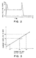
- Figure 2 is a graph which shows the change in the force necessary to peel away the sealing member.
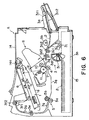
- Figure 3 is a graph which shows the change in the amount of the torque to be generated by the motor, and the change in the value of the current necessary for generating the torque.
- Figure 4 is a block diagram of the structure for controlling the motor in the primary embodiment of the present invention.
- Figure 5 is a flow chart which shows a sequence in which it is detected whether or not the sealing member of a process cartridge inserted into the main assembly of an image forming apparatus has been wound away, and a sequence in which the sealing member is peeled away.
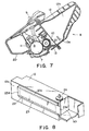
- Figure 6 is a vertical sectional view of an example of an image forming apparatus to which the present invention is applicable.
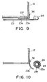
- Figure 7 is a vertical sectional view of a process cartridge, which shows the interior of the cartridge.
- Figure 8 is a perspective view of an automatic sealing member winding apparatus, which depicts the basic structure of the apparatus.
- Figure 9 is a sectional view of the winding shaft and its adjacencies, which shows the placement of the adhesive for preventing the sealing member from loosening after being completely wound into a roll.
- Figure 10 is a sectional view of the winding shaft and its adjacencies, which shows the placement of the adhesive for preventing the sealing member from loosening after being completely wound into a roll.
- Figure 6 is a drawing which shows the structure of the main assembly 15 of a laser beam printer, that is, an example of an image forming apparatus, in accordance with the present invention, and the process cartridge in accordance with the present invention in the main assembly 15.
- Figure 7 is a drawing which shows the structure of the process cartridge.
- an image forming apparatus A forms a developer image (which hereinafter will be called a toner image) on a photosensitive drum 7, which is an electrophotographic photosensitive member, by exposing the photosensitive drum 7 to an optical image, in accordance with image information, projected from an optical system 1. While a toner image is formed, a piece of recording medium 2 is conveyed by a conveying means 3 in synchronism with toner image formation, and as the recording medium 2 is conveyed, the toner image formed on the photosensitive drum 7 is transferred onto the recording medium 2 by a transferring means 4 in the image forming portion of a process cartridge B.
- a developer image which hereinafter will be called a toner image
- the recording medium 2 is conveyed to a fixing means 5 comprising a pressure roller 5a and heat roller 5b.
- the fixing means 5 the transferred toner image is fixed to the recording medium 2.
- the recording medium 2 is discharged to a delivery portion 6.
- the optical system 1 is a system which projects to the photosensitive drum 7 an optical image in accordance with the image information read into the image forming apparatus from an external apparatus or the like.
- the optical unit la on the main apparatus side of an image forming apparatus contains an unillustrated laser diode, a polygon mirror lb, a scanner motor lc, a focusing lens ld, and a deflection mirror le.
- the laser diode emits light in response to the image signal, and this light is projected as an image light to the polygon mirror lb, which is being rotated at a high velocity by the scanner motor lc. After being reflected by the polygon mirror lb, the light is projected to the photosensitive drum 7 through the focusing lens 1k and the deflection mirror le, and selectively exposes the surface of the photosensitive drum 7.
- the recording medium 2 can be fed in two different manners: manually, or with the use of a cassette.
- a manual feeding of the recording medium 2 first, a plurality of sheets of the recording medium 2 are set in a sheet feeder tray 3a.
- the recording media 2 in the sheet feeder tray 3a is fed one by one into the image forming apparatus by a pickup roller 3b, being separated from the following sheets of recording medium by a pair of separation rollers 3c1 and 3c2, in such a manner that the leading edge of each recording medium 2 comes into contact with a pair of registration rollers 3d1 and 3d2.
- the pair of registration rollers 3d1 and 3d2 are rotationally driven in such a manner that the recording medium 2 is conveyed to the image forming portion in synchronism with image formation.
- the recording medium 2 is conveyed to a fixing means 5.
- the recording medium 2 is discharged into a delivery portion 6, through a reversing path, by a pair of intermediary discharge rollers 3e, and a pair of final discharge rollers 3fl and 3f2.
- the sheet feeder tray 3a comprises an internal member 3a1 and an external member 3a2.
- the internal i member 3a1 is stored within the external member 3a2 in such a manner that the external member 3a1 constitutes a part of the external shell of the apparatus main assembly 15.
- the bottom portion of the apparatus main assembly 15 is provided with a portion, or a space, into which a cassette 3h is installed.
- a plurality of recording media 2 stored within the sheet feeder cassette 3h are fed out of the cassette one by one, starting from the top, by a pickup roller 3i, and are conveyed to the pair of registration rollers 3d1 and 3d2 by conveyer roller 3j. After being passed through the pair of registration rollers 3d1 and 3d2, the conveyance of the recording medium 2 is the same as that in the case of the manual feeding of the recording medium 2.
- the transferring means 4 is a means for transferring a toner image formed on the photosensitive drum 7 in the image forming portion onto the recording medium 2.
- the transferring means 4 in this embodiment comprises a transfer roller 4, which presses the recording medium 2 upon the photosensitive drum 7 of the installed process cartridge B, and as the electrical voltage opposite in polarity to the toner image formed on the photosensitive drum 7 is applied to the transfer roller 4, the toner image on the photosensitive drum 7 is transferred onto the recording medium 2.
- the fixing means 5 is a means for fixing to the recording medium 2, the toner image which has been transferred onto the recording medium 2 through the application of electrical voltage to the transfer roller 4.
- the fixing means 5 comprises a driving roller 5a, which is rotationally driven, and a fixing roller 5 which contains a heat generating portion and follows the rotation of the driving roller 5a by being pressed upon the driving roller 5a.
- the process cartridge B is a cartridge which contains an electrophotographic photosensitive member i and a minimum of one processing means.
- processing means there are a charging means for charging the surface of the electrophotographic photosensitive member, a developing means for forming a toner image on the electrophotographic photosensitive member, a cleaning means for removing the toner particles remaining on the surface of the electrophotographic photosensitive member, and the like.
- the process cartridge B may be a development cartridge which lacks the photosensitive drum 7 but has a developing means.
- the process cartridge B in this embodiment comprises the photosensitive drum 7, a charge roller 8 as a charging means, an exposing portion 9, a development roller 10 as a developer carrying member, and a cleaning means 11.
- the charge roller 8, exposing means 9, development roller 9, and cleaning means 11 are disposed around the photosensitive drum 7.
- These components, portions, and means are covered with a combination of a developing means housing 13 and a cleaning means housing 20, and are integrated with a toner container 12, that is, a developer storage container, so that they can be removably installed in the main assembly 15 of an image forming apparatus.
- the process cartridge B also comprises a stirring member 10a for sending the toner stored in the toner storing portion 12b of the toner container 12, to the development roller 10.
- the process cartridge B is provided with an opening 22, which is in the partitioning wall 12a between the toner container 12 and a development chamber 21 ( Figure 7), and through which developer is supplied.
- This opening 22 is sealed with a sealing member 23 which is thermally welded to the partitioning wall 12a by a method such as hot melt to keep the toner sealed within the toner container 12.
- the sealing member 23 is extended from the right side of the opening 22 to the left side of the opening 22, sealing the opening 22, with the sealing portions 23c with which the sealing member 23 is provided being pasted to the edges of the opening 22, and is folded back at a folding point 23d located on the left side of the opening 22, being extended rightward beyond the starting point of the sealing member 23.
- the end portion 23e of the portion of the sealing member 23 extended beyond the starting point is attached to a winding shaft 24.
- the trailing end (right end) portion 23f of the sealing member 23 is coated with adhesive 23a.
- the top surface of the adhesive 23a is covered with a piece of paper 23 capable of easily separating from the adhesive, to prevent the trailing end portion 23f of the sealing member 23 from adhering to the other portions of the sealing member 23.
- the end portion of the separation paper 23b, which extends beyond the trailing end (right end) portion 23f of the sealing member 23, is fixed to the toner container 12 with the use of a fastener 36 or the like.
- the sealing member 23 After being wound, the sealing member 23 can remain wound around the winding shaft 24, as shown in Figure 10, because of the presence of the adhesive 23a coated on the trailing portion 23f (the portion of the sealing member 23 wound last around the winding shaft 24).
- the winding shaft 24 is disposed within a winding shaft storing portion 50 integrally formed with the toner container 12.
- the direction of the winding shaft 24 is parallel to the shorter edges of the opening 22.
- the winding shaft storing portion 50 is located next to the toner container 12 in terms of the longitudinal direction of the toner container, being separated from the toner storing portion 12b by a wall.
- Figure 1 shows the positioning of the gears of the winding shaft portion.
- the winding shaft 24 is rotationally supported by the toner container 12.
- the sealing member 23 is welded, and to the top end portion of the winding shaft 24, a winding gear 25 is fixed.
- This gear 25 is engaged with a worm gear fixed to a rotational shaft 26a.
- the rotational shaft 26a is supported by the toner container 12 with the interposition of unillustrated bearings between the rotational shaft 26a and container 12.
- a spur gear 27 is fixed to this shaft 26a of the worm gear 26, a spur gear 27 is fixed.
- the spur gear 27 is indirectly engaged with a gear 29 of a power output shaft 28 of a motor 30, with the interposition of a stepped gear 31 between the spur gear 27 and the gear 29.
- the stepped gear 31 is rotationally engaged with a stationary shaft 31a fixed to the toner container 12.
- the train of these gears constitutes a velocity reduction mechanism for transmitting the rotation of the output shaft 38 of the motor 30 to the winding shaft 24 while reducing velocity.
- the torque of the motor 30 is amplified by this velocity reducing mechanism to provide the winding shaft 24 with a necessary amount of torque.
- the motor 30 is anchored within the process cartridge B with the use of an unillustrated means.
- This motor 30 is provided with an unillustrated harness through which electrical power is supplied to the motor 30 from an electrical power source on the side of the apparatus main assembly 15.
- the motor 30, and the gear 29 fixed to the motor shaft 28 may be located on the side of the apparatus main assembly 15.
- the gear 31 of the process cartridge B engages with the gear 29 of the apparatus main assembly 29.
- the gears 29 and 31 constitute the connecting portions on the sides of the apparatus main assembly 15 and process cartridge B, respectively, which engage with'each other as the process cartridge B is installed into the apparatus main assembly 15.
- the change in the amount of pulling force necessary to open the sealing member 23 is as follows. Referring to Figure 2, the aforementioned amount of force reaches the first peak of D kg at the beginning of the peeling of the sealing member 23, and decreases to E kg, remaining there until it hits the second peak of G kg at almost the end of the peeling. After the second peak, the sealing member 23 is completely wound away around the winding shaft 24, the amount of the force decreasing to a force of F kg, which is equivalent to the amount of force necessary to rotate the winding shaft alone.
- the amount of the force necessary to peel away the sealing member 23 is relatively greater at the end portions of the sealing portion 23d and 23e compared to the center portion of the sealing portion 23c. Therefore, the sealing member winding shaft 24 needs to be strong enough to withstand both the peak amounts of the pulling force, and the motor 30 needs to generate torque high enough to provide the sealing member 23 with the peak amounts of the pulling force. In other words, the motor 30 is required to generate torque higher than the torque which generates the pulling forces of D kg and K kg, that is, the forces which apply to the end portion 23f of the sealing member 23 as shown in the drawing.
- the motor 30 used in this embodiment is a DC motor driven by electrical power, for example, a DC voltage of 5 V, supplied from the DC power source 32 illustrated in Figure 4.
- a DC controller 33 that is, a controlling means, of the apparatus main assembly 15
- the value of the electrical current which flows through the motor 30, that is, the mechanical power source can be determined based on the output from the current value detecting circuit 34 of the apparatus main assembly 15.
- the amount of the torque outputted by the motor 30 through the output shaft is Td.
- This torque of Td is equivalent to the pulling force of D kg or G kg generated by the winding shaft 24, that is, the force necessary to be generated by the winding shaft 34 at the beginning or the end of the peeling of the sealing member 23.
- a current of Ie is supplied to the motor 30 so that the motor generates a torque of Te, which is equivalent to the pulling force of E kg with which the sealing member 23 is pulled.
- the output shaft of the motor 30 is provided with a toque of Tf by the motor 30. This is the state in which the smallest amount of pulling force of F kg is being generated, indicating that the sealing member peeling operation has completed, or the winding shaft 24 of the process cartridge B is being rotated after the completion of the peeling of the sealing member 23.
- a motor (30) dedicated for winding away the sealing member 23 is provided so that the motor (30), that is, the mechanical power source for driving the winding shaft 24, is not affected by the load from the development roller 10 and stirring member 10a.
- FIG 4 is a drawing which shows the concept of the present invention.
- the electrical voltage supplied from the DC power source 32 is supplied to the motor 30 by way of the electric current detecting circuit 34.
- This electrical current detecting circuit 34 has a simple structure in that a resistive element (unillustrated) is placed as a part of the power supply route, and the voltage between the two ends of the resistive element is detected. The current value calculated from this voltage, that is, the resistance value of the resistive element, is constantly monitored and transmitted as information to the DC controller 33.
- the DC controller 33 turns on or off the power from the DC power source 32 to the motor 30.
- the power source 32 of the image forming apparatus main assembly 15 is turned on (S1). As the power source 32 is turned on, image information is transmitted from the controller 33, a print start signal is sent, and a voltage of a predetermined level is applied only a brief moment after the power source is turned on (S2).
- the length of the period in which power is temporarily supplied to the motor 30 may be short, because this period is the period in which only the operation for measuring the load which applies to the motor 30 is carried out.
- a predetermined value S3
- an unillustrated CPU of the apparatus main assembly 15 determines that the inserted process cartridge B is a brand-new process cartridge, that is, a process cartridge in which the sealing member 23 has not been peeled away, and applies voltage to the motor 30 for a predetermined length T of time (S4).
- This length T of time is approximately equal to the amount of time sufficient for completely peeling away the sealing member 23.
- the operational sequence repeats the step for measuring and comparing the current value (S5).
- the CPU determines that the operation for peeling away the sealing member 23 has been completed, and initiates an ordinary image forming operation (S6).
- an ordinary image forming operation S6
- fresh toner flows into the development chamber, and therefore, the developing means itself, instead of the winding shaft 23, idly rotates, sometimes until the amount of the toner within the development chamber reaches the proper level for image formation.
- the current value flowing through the motor 30 measured the first time is no greater than the predetermined value, it is determined that the installed cartridge B is a process cartridge in which the sealing member 23 has been wound away, and the rotation of the motor 30 is instantly stopped, and an ordinary image forming operation is initiated (S6). After the image forming operation, the image forming apparatus main assembly is stopped (S7).
- the position to which the motor 30 is mounted may be either within the process cartridge B or within the image forming apparatus main assembly 15 as long as the positioning of the motor 30 does not create a problem regarding the transmission of driving force.
- the advantage in placing the motor 30 in the process cartridge B is that the motor 30 and sealing member winding shaft 24 are connected to each other within the process cartridge B in terms of the force for driving the shaft 24, and therefore, the interface between the image forming apparatus main assembly 15 and process cartridge B becomes simple.
- all that needs attention when configuring the interface between the image forming apparatus main assembly 15 and the process cartridge B is the driving of the main components such as the photosensitive drum, development roller, and the like in the process cartridge B, which concern image formation, and the supplying of electrical signals and electrical voltage.
- the state of the sealing member 23 and the time when the sealing member 23 has been completely peeled away can be detected from the value of the current flowing through the motor 30 regardless of where the motor 30 is mounted.
- Figure 7 shows a process cartridge in accordance with the present invention
- the present invention also applies to a development cartridge comprising a developer bearing member, a developer containing portion which stores the developer to be supplied to the developer bearing member, a sealing member for sealing the opening through which the developer within the developer containing portion is supplied to the developer bearing member, and an automatic sealing member winding apparatus, and it applies to an electrophotographic image forming apparatus in which such a development cartridge is detachably mountable.
- a motor was employed as the source for providing force for driving the winding shaft.
- a rotary actuator, a direct drive actuator, or the like may be employed in place of a motor.
Landscapes
- Physics & Mathematics (AREA)
- General Physics & Mathematics (AREA)
- Engineering & Computer Science (AREA)
- Computer Vision & Pattern Recognition (AREA)
- Electrophotography Configuration And Component (AREA)
- Dry Development In Electrophotography (AREA)
Applications Claiming Priority (2)
| Application Number | Priority Date | Filing Date | Title |
|---|---|---|---|
| JP34234199 | 1999-12-01 | ||
| JP34234199A JP2001159841A (ja) | 1999-12-01 | 1999-12-01 | 現像カートリッジ及びプロセスカートリッジ及び電子写真画像形成装置 |
Publications (3)
| Publication Number | Publication Date |
|---|---|
| EP1107073A2 true EP1107073A2 (de) | 2001-06-13 |
| EP1107073A3 EP1107073A3 (de) | 2002-11-20 |
| EP1107073B1 EP1107073B1 (de) | 2006-06-14 |
Family
ID=18352985
Family Applications (1)
| Application Number | Title | Priority Date | Filing Date |
|---|---|---|---|
| EP00310607A Expired - Lifetime EP1107073B1 (de) | 1999-12-01 | 2000-11-30 | Bilderzeugungsgerät mit kontrollierter Antriebsquelle für das Abziehen eines Dichtungselementes in einer Entwicklungseinheit |
Country Status (4)
| Country | Link |
|---|---|
| US (1) | US6516168B2 (de) |
| EP (1) | EP1107073B1 (de) |
| JP (1) | JP2001159841A (de) |
| DE (1) | DE60028702T2 (de) |
Cited By (2)
| Publication number | Priority date | Publication date | Assignee | Title |
|---|---|---|---|---|
| EP1170641A3 (de) * | 2000-07-07 | 2003-03-26 | Canon Kabushiki Kaisha | Entwicklungseinheit, Arbeitseinheit und elektrophotographisches Bilderzeugungsgerät |
| EP1696284A3 (de) * | 2005-02-28 | 2006-11-29 | Brother Kogyo Kabushiki Kaisha | Bilderzeugungsvorrichtung und Entwicklerkartusche mit Informationsbauteil für anfängliche Entwicklermenge |
Families Citing this family (24)
| Publication number | Priority date | Publication date | Assignee | Title |
|---|---|---|---|---|
| WO2003016138A1 (fr) * | 2001-08-20 | 2003-02-27 | Yuyama Mfg. Co., Ltd. | Dispositif de distribution de comprimes |
| US6947687B2 (en) * | 2002-06-07 | 2005-09-20 | Canon Kabushiki Kaisha | Cartridge having locking portion for locking cartridge with an image forming apparatus and releasing portion to release the locking portion, and image forming apparatus having such a cartridge |
| JP3984900B2 (ja) * | 2002-09-30 | 2007-10-03 | キヤノン株式会社 | 離間部材及びプロセスカートリッジ |
| JP2005099691A (ja) * | 2003-08-29 | 2005-04-14 | Canon Inc | プロセスカートリッジ及び電子写真画像形成装置 |
| JP3919779B2 (ja) * | 2003-08-29 | 2007-05-30 | キヤノン株式会社 | 電子写真画像形成装置 |
| KR100636239B1 (ko) * | 2005-06-02 | 2006-10-19 | 삼성전자주식회사 | 전자사진방식 칼라화상형성장치 |
| US7929881B2 (en) * | 2006-12-11 | 2011-04-19 | Canon Kabushiki Kaisha | Process cartridge and electrophotographic image forming apparatus |
| JP4968957B2 (ja) | 2008-03-31 | 2012-07-04 | キヤノン株式会社 | 枠体ユニット、現像装置及びプロセスカートリッジ、並びに、枠体ユニット、現像装置及びプロセスカートリッジの製造方法 |
| JP4701266B2 (ja) * | 2008-05-27 | 2011-06-15 | キヤノン株式会社 | プロセスカートリッジ及び電子写真画像形成装置 |
| EP2219027A1 (de) | 2009-02-12 | 2010-08-18 | Centre National de la Recherche Scientifique | Vorrichtungen und Verfahren zur Beobachtung der Zellteilung |
| JP5570237B2 (ja) * | 2009-03-02 | 2014-08-13 | キヤノン株式会社 | 画像形成装置 |
| JP2011123348A (ja) * | 2009-12-11 | 2011-06-23 | Canon Inc | プロセスカートリッジ及びプロセスカートリッジの分解方法 |
| JP5355679B2 (ja) | 2011-12-27 | 2013-11-27 | キヤノン株式会社 | プロセスカートリッジ及び画像形成装置 |
| JP6223419B2 (ja) | 2012-03-29 | 2017-11-01 | サントル・ナシオナル・ドゥ・ラ・ルシェルシュ・シアンティフィクCentre National De Larecherche Scientifique | 細胞壁をもつ細胞または長方形の卵殻をもつ無脊椎動物胚の細胞を観察するための方法 |
| CA2875930C (en) | 2012-06-15 | 2023-06-13 | Canon Kabushiki Kaisha | Cartridge, process cartridge and electrophotographic image forming apparatus |
| JP5358772B1 (ja) * | 2013-01-17 | 2013-12-04 | 三重県 | ドライフルーツ、及びその製造方法 |
| JP6338460B2 (ja) | 2013-08-20 | 2018-06-06 | キヤノン株式会社 | カートリッジ及び画像形成装置 |
| JP6376749B2 (ja) | 2013-12-06 | 2018-08-22 | キヤノン株式会社 | プロセスカートリッジおよび電子写真画像形成装置 |
| CN107148736B (zh) * | 2014-12-12 | 2019-06-07 | 新日铁住金株式会社 | 电源装置、接合系统及通电加工方法 |
| JP6671997B2 (ja) | 2015-02-05 | 2020-03-25 | キヤノン株式会社 | カートリッジ、感光体ユニット、電子写真画像形成装置 |
| JP6552212B2 (ja) | 2015-02-16 | 2019-07-31 | キヤノン株式会社 | カートリッジ及び画像形成装置並びにカートリッジの製造方法 |
| JP6598468B2 (ja) | 2015-02-16 | 2019-10-30 | キヤノン株式会社 | カートリッジ及び画像形成装置並びにカートリッジの製造方法 |
| JP7822835B2 (ja) * | 2022-03-11 | 2026-03-03 | キヤノン株式会社 | 現像容器、現像装置、プロセスカートリッジ及び画像形成装置 |
| JP2024087334A (ja) * | 2022-12-19 | 2024-07-01 | キヤノン株式会社 | 画像形成装置 |
Family Cites Families (15)
| Publication number | Priority date | Publication date | Assignee | Title |
|---|---|---|---|---|
| US4969557A (en) * | 1985-11-26 | 1990-11-13 | Ricoh Co., Ltd. | Toner cartridge |
| JPS6449864U (de) * | 1987-09-17 | 1989-03-28 | ||
| JPH0815940A (ja) | 1994-04-28 | 1996-01-19 | Canon Inc | 現像フレーム及びプロセスカートリッジ及び画像形成装置 |
| JP2877729B2 (ja) | 1994-04-28 | 1999-03-31 | キヤノン株式会社 | シャッタ部材及びプロセスカートリッジ及び画像形成装置 |
| JP2877728B2 (ja) | 1994-04-28 | 1999-03-31 | キヤノン株式会社 | プロセスカートリッジ及び画像形成装置 |
| JPH08314247A (ja) * | 1995-05-16 | 1996-11-29 | Canon Inc | 現像装置、プロセスカートリッジおよび画像形成装置 |
| US5768658A (en) | 1995-07-21 | 1998-06-16 | Canon Kabushiki Kaisha | Electrode member, developing apparatus, process cartridge and image forming apparatus |
| US6070029A (en) | 1995-07-31 | 2000-05-30 | Canon Kabushiki Kaisha | Coupling member, process cartridge, electrophotographic image forming apparatus and assembling method |
| JP3406125B2 (ja) * | 1995-07-31 | 2003-05-12 | 京セラミタ株式会社 | 画像形成装置 |
| JP3402860B2 (ja) | 1995-07-31 | 2003-05-06 | キヤノン株式会社 | プロセスカートリッジ及び電子写真画像形成装置 |
| US5893006A (en) | 1995-07-31 | 1999-04-06 | Canon Kabushiki Kaisha | Process cartridge detectably mountable to image forming apparatus and image forming apparatus using same |
| US5940657A (en) | 1996-03-05 | 1999-08-17 | Canon Kabushiki Kaisha | Developing cartridge |
| JP3869903B2 (ja) | 1996-03-05 | 2007-01-17 | キヤノン株式会社 | 電子写真画像形成装置 |
| US5950049A (en) | 1996-03-05 | 1999-09-07 | Canon Kabushiki Kaisha | Developing cartridge |
| JP3332818B2 (ja) | 1996-08-29 | 2002-10-07 | キヤノン株式会社 | プロセスカートリッジ及び電子写真画像形成装置及び接続端子の接続方法 |
-
1999
- 1999-12-01 JP JP34234199A patent/JP2001159841A/ja not_active Withdrawn
-
2000
- 2000-11-30 DE DE60028702T patent/DE60028702T2/de not_active Expired - Lifetime
- 2000-11-30 US US09/725,804 patent/US6516168B2/en not_active Expired - Fee Related
- 2000-11-30 EP EP00310607A patent/EP1107073B1/de not_active Expired - Lifetime
Cited By (4)
| Publication number | Priority date | Publication date | Assignee | Title |
|---|---|---|---|---|
| EP1170641A3 (de) * | 2000-07-07 | 2003-03-26 | Canon Kabushiki Kaisha | Entwicklungseinheit, Arbeitseinheit und elektrophotographisches Bilderzeugungsgerät |
| US6735403B2 (en) | 2000-07-07 | 2004-05-11 | Canon Kabushiki Kaisha | Image forming apparatus to which a developing cartridge or process cartridge are detachably mountable comprising driving control means for permitting and preventing transmission of a driving force to a winding member |
| EP1696284A3 (de) * | 2005-02-28 | 2006-11-29 | Brother Kogyo Kabushiki Kaisha | Bilderzeugungsvorrichtung und Entwicklerkartusche mit Informationsbauteil für anfängliche Entwicklermenge |
| US7512347B2 (en) | 2005-02-28 | 2009-03-31 | Brother Kogyo Kabushiki Kaisha | Image-forming device capable of determining information on a detachably mounted developer cartridge and developer cartridge for use therein |
Also Published As
| Publication number | Publication date |
|---|---|
| DE60028702T2 (de) | 2007-03-29 |
| JP2001159841A (ja) | 2001-06-12 |
| DE60028702D1 (de) | 2006-07-27 |
| US20010005460A1 (en) | 2001-06-28 |
| EP1107073A3 (de) | 2002-11-20 |
| EP1107073B1 (de) | 2006-06-14 |
| US6516168B2 (en) | 2003-02-04 |
Similar Documents
| Publication | Publication Date | Title |
|---|---|---|
| EP1107073B1 (de) | Bilderzeugungsgerät mit kontrollierter Antriebsquelle für das Abziehen eines Dichtungselementes in einer Entwicklungseinheit | |
| US6301457B1 (en) | Coupling member, process cartridge and image forming apparatus | |
| US7231164B2 (en) | Developing unit, developing cartridge, and image forming apparatus | |
| US6496667B2 (en) | Cartridge detachably attachable to image forming apparatus | |
| EP0331324B1 (de) | Bilderzeugungsgerät mit herausnehmbarer Prozesskassette | |
| US9229371B2 (en) | Developer container, developing cartridge, process cartridge and image forming apparatus | |
| US9188906B2 (en) | Cartridge, developing cartridge, process cartridge and image forming apparatus | |
| US9069289B2 (en) | Developer container, developing cartridge, process cartridge and image forming apparatus | |
| US6804476B2 (en) | Process cartridge and developing device detachably attachable to image forming apparatus main body and having developer seal member with grip portion, and such image forming apparatus | |
| JP3997213B2 (ja) | 電子写真画像形成装置 | |
| EP0344072A2 (de) | System für die Steuerung des Antriebes eines Tonerrüttlers in einem Bildaufzeichnungsgerät und dieses System beinhaltendes Bildaufzeichnungsgerät | |
| JP2004205950A (ja) | クリーニング装置、プロセスカートリッジおよび画像形成装置 | |
| US5359400A (en) | Image forming apparatus | |
| JP2003076249A (ja) | プロセスカートリッジおよび電子写真画像形成装置 | |
| US9904208B2 (en) | Accommodating container, cleaning device, developing device, process cartridge, and image forming apparatus | |
| JP2002328569A (ja) | プロセスカートリッジ及び現像装置の初期設定方法及び電子写真画像形成装置 | |
| US12529980B2 (en) | Image forming apparatus | |
| US20180239277A1 (en) | Image forming apparatus | |
| JPH09288425A (ja) | トナーシール自動開封装置及びプロセスカートリッジ及び電子写真画像形成装置 | |
| JP5016796B2 (ja) | カートリッジ及び電子写真画像形成装置 | |
| JP2002278240A (ja) | 電子写真画像形成装置 | |
| JP3408051B2 (ja) | 現像剤残量検知装置 | |
| JP2008233698A (ja) | 画像形成装置 | |
| JP4235401B2 (ja) | 画像形成装置 | |
| JPH11258964A (ja) | 電子写真式画像形成装置 |
Legal Events
| Date | Code | Title | Description |
|---|---|---|---|
| PUAI | Public reference made under article 153(3) epc to a published international application that has entered the european phase |
Free format text: ORIGINAL CODE: 0009012 |
|
| AK | Designated contracting states |
Kind code of ref document: A2 Designated state(s): AT BE CH CY DE DK ES FI FR GB GR IE IT LI LU MC NL PT SE TR |
|
| AX | Request for extension of the european patent |
Free format text: AL;LT;LV;MK;RO;SI |
|
| PUAL | Search report despatched |
Free format text: ORIGINAL CODE: 0009013 |
|
| AK | Designated contracting states |
Kind code of ref document: A3 Designated state(s): AT BE CH CY DE DK ES FI FR GB GR IE IT LI LU MC NL PT SE TR |
|
| AX | Request for extension of the european patent |
Free format text: AL;LT;LV;MK;RO;SI |
|
| 17P | Request for examination filed |
Effective date: 20030403 |
|
| AKX | Designation fees paid |
Designated state(s): DE FR GB IT |
|
| 17Q | First examination report despatched |
Effective date: 20041015 |
|
| GRAP | Despatch of communication of intention to grant a patent |
Free format text: ORIGINAL CODE: EPIDOSNIGR1 |
|
| RTI1 | Title (correction) |
Free format text: IMAGE FORMING APPARATUS WITH CONTROLLED DRIVE SOURCE FOR REMOVAL OF A SEALING MEMBER IN A DEVELOPING CARTRIDGE |
|
| GRAS | Grant fee paid |
Free format text: ORIGINAL CODE: EPIDOSNIGR3 |
|
| GRAA | (expected) grant |
Free format text: ORIGINAL CODE: 0009210 |
|
| AK | Designated contracting states |
Kind code of ref document: B1 Designated state(s): DE FR GB IT |
|
| PG25 | Lapsed in a contracting state [announced via postgrant information from national office to epo] |
Ref country code: IT Free format text: LAPSE BECAUSE OF FAILURE TO SUBMIT A TRANSLATION OF THE DESCRIPTION OR TO PAY THE FEE WITHIN THE PRESCRIBED TIME-LIMIT;WARNING: LAPSES OF ITALIAN PATENTS WITH EFFECTIVE DATE BEFORE 2007 MAY HAVE OCCURRED AT ANY TIME BEFORE 2007. THE CORRECT EFFECTIVE DATE MAY BE DIFFERENT FROM THE ONE RECORDED. Effective date: 20060614 |
|
| REG | Reference to a national code |
Ref country code: GB Ref legal event code: FG4D |
|
| REF | Corresponds to: |
Ref document number: 60028702 Country of ref document: DE Date of ref document: 20060727 Kind code of ref document: P |
|
| ET | Fr: translation filed | ||
| PLBE | No opposition filed within time limit |
Free format text: ORIGINAL CODE: 0009261 |
|
| STAA | Information on the status of an ep patent application or granted ep patent |
Free format text: STATUS: NO OPPOSITION FILED WITHIN TIME LIMIT |
|
| 26N | No opposition filed |
Effective date: 20070315 |
|
| PGFP | Annual fee paid to national office [announced via postgrant information from national office to epo] |
Ref country code: IT Payment date: 20091119 Year of fee payment: 10 Ref country code: FR Payment date: 20091202 Year of fee payment: 10 Ref country code: GB Payment date: 20091204 Year of fee payment: 10 |
|
| PGFP | Annual fee paid to national office [announced via postgrant information from national office to epo] |
Ref country code: DE Payment date: 20091130 Year of fee payment: 10 |
|
| GBPC | Gb: european patent ceased through non-payment of renewal fee |
Effective date: 20101130 |
|
| REG | Reference to a national code |
Ref country code: FR Ref legal event code: ST Effective date: 20110801 |
|
| REG | Reference to a national code |
Ref country code: DE Ref legal event code: R119 Ref document number: 60028702 Country of ref document: DE Effective date: 20110601 Ref country code: DE Ref legal event code: R119 Ref document number: 60028702 Country of ref document: DE Effective date: 20110531 |
|
| PG25 | Lapsed in a contracting state [announced via postgrant information from national office to epo] |
Ref country code: DE Free format text: LAPSE BECAUSE OF NON-PAYMENT OF DUE FEES Effective date: 20110531 |
|
| PG25 | Lapsed in a contracting state [announced via postgrant information from national office to epo] |
Ref country code: FR Free format text: LAPSE BECAUSE OF NON-PAYMENT OF DUE FEES Effective date: 20101130 |
|
| PG25 | Lapsed in a contracting state [announced via postgrant information from national office to epo] |
Ref country code: GB Free format text: LAPSE BECAUSE OF NON-PAYMENT OF DUE FEES Effective date: 20101130 |
|
| PG25 | Lapsed in a contracting state [announced via postgrant information from national office to epo] |
Ref country code: IT Free format text: LAPSE BECAUSE OF NON-PAYMENT OF DUE FEES Effective date: 20101130 |