EP1106468A1 - Verfahren und Schaltungsanordnung zum Vermeiden ungewollten Ansprechens von Gleisstromkreisen - Google Patents
Verfahren und Schaltungsanordnung zum Vermeiden ungewollten Ansprechens von Gleisstromkreisen Download PDFInfo
- Publication number
- EP1106468A1 EP1106468A1 EP00125820A EP00125820A EP1106468A1 EP 1106468 A1 EP1106468 A1 EP 1106468A1 EP 00125820 A EP00125820 A EP 00125820A EP 00125820 A EP00125820 A EP 00125820A EP 1106468 A1 EP1106468 A1 EP 1106468A1
- Authority
- EP
- European Patent Office
- Prior art keywords
- operating voltage
- main switch
- switching
- traction
- switch
- Prior art date
- Legal status (The legal status is an assumption and is not a legal conclusion. Google has not performed a legal analysis and makes no representation as to the accuracy of the status listed.)
- Granted
Links
- 238000000034 method Methods 0.000 title claims abstract description 10
- 230000003137 locomotive effect Effects 0.000 claims description 20
- 101000608734 Helianthus annuus 11 kDa late embryogenesis abundant protein Proteins 0.000 claims description 4
- 230000003111 delayed effect Effects 0.000 claims description 2
- -1 DS21 Proteins 0.000 claims 1
- 101000623061 Drosophila melanogaster 40S ribosomal protein S26 Proteins 0.000 claims 1
- 230000004913 activation Effects 0.000 description 1
- 230000008878 coupling Effects 0.000 description 1
- 238000010168 coupling process Methods 0.000 description 1
- 238000005859 coupling reaction Methods 0.000 description 1
- 238000001514 detection method Methods 0.000 description 1
- 230000011664 signaling Effects 0.000 description 1
Images
Classifications
-
- B—PERFORMING OPERATIONS; TRANSPORTING
- B60—VEHICLES IN GENERAL
- B60L—PROPULSION OF ELECTRICALLY-PROPELLED VEHICLES; SUPPLYING ELECTRIC POWER FOR AUXILIARY EQUIPMENT OF ELECTRICALLY-PROPELLED VEHICLES; ELECTRODYNAMIC BRAKE SYSTEMS FOR VEHICLES IN GENERAL; MAGNETIC SUSPENSION OR LEVITATION FOR VEHICLES; MONITORING OPERATING VARIABLES OF ELECTRICALLY-PROPELLED VEHICLES; ELECTRIC SAFETY DEVICES FOR ELECTRICALLY-PROPELLED VEHICLES
- B60L15/00—Methods, circuits, or devices for controlling the traction-motor speed of electrically-propelled vehicles
- B60L15/32—Control or regulation of multiple-unit electrically-propelled vehicles
-
- B—PERFORMING OPERATIONS; TRANSPORTING
- B61—RAILWAYS
- B61L—GUIDING RAILWAY TRAFFIC; ENSURING THE SAFETY OF RAILWAY TRAFFIC
- B61L1/00—Devices along the route controlled by interaction with the vehicle or train
- B61L1/20—Safety arrangements for preventing or indicating malfunction of the device, e.g. by leakage current, by lightning
-
- B—PERFORMING OPERATIONS; TRANSPORTING
- B60—VEHICLES IN GENERAL
- B60L—PROPULSION OF ELECTRICALLY-PROPELLED VEHICLES; SUPPLYING ELECTRIC POWER FOR AUXILIARY EQUIPMENT OF ELECTRICALLY-PROPELLED VEHICLES; ELECTRODYNAMIC BRAKE SYSTEMS FOR VEHICLES IN GENERAL; MAGNETIC SUSPENSION OR LEVITATION FOR VEHICLES; MONITORING OPERATING VARIABLES OF ELECTRICALLY-PROPELLED VEHICLES; ELECTRIC SAFETY DEVICES FOR ELECTRICALLY-PROPELLED VEHICLES
- B60L2200/00—Type of vehicles
- B60L2200/26—Rail vehicles
Definitions
- the track sections of rail systems are in sections divided to run multiple trains at the same time to allow a route.
- each section of track only enter a train when the track section is "free" is reported, d. H. if it is certain that no one else Train moved in this section of track.
- the free or busy message takes place in modern rail systems with an automatic Train detection system.
- the recording takes place over the tracks with the help of track circuits.
- there the two tracks of the track section lie at the poles one DC or low frequency voltage. Will the track section driven by a train, so the wheels over the Short axles ago, the measured technically and can be evaluated in terms of signaling.
- the inrush current of the locomotive transformers is a source of interference current When switching on a transformer flows through the so-called "inrush", i.e. that is, by the Structure of the magnetic field in the transformer core, in the an asymmetrical current during the first half-wave. Asymmetry of But current means a DC component.
- This direct current can with an unfavorable phase position of the operating voltage in Moment of turning on the vehicle transformer Measuring current of the track circuit must be opposite.
- the track circuit must therefore be set so that it tolerates this interference current caused by a locomotive.
- One problem here is the coupling of several Locomotives represented by the parallel switched on Transformers an inrush current at a considerable amount can be caused.
- the resulting direct current can only be done by appropriate dimensioning of the track circuit then can no longer be controlled and possibly caused an unwanted response of the track circuit, so that the track section in question was incorrectly reported free becomes.
- the invention has for its object a method and specify a circuit arrangement with which an unwanted Addressing of track circuits when commissioning coupled Traction vehicles is safely avoided.
- the main switches of the locomotives are hard- or software chained together so that they, beginning from the occupied driver's cab at one end of the locomotive association, delayed in the order of the locomotives be switched on.
- each locomotive is looped together that the loop output of a locomotive after switching on of the main switch of the locomotive with a time delay the control operating voltage is applied, which then on Release of the loop of the following traction vehicle the activation of its main switch.
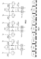
- FIG. 1 For a better understanding of the circuit arrangement as it 2 is shown in FIG. 1 is a vehicle group, consisting of three locomotives.
- the locomotives each have a front and a rear Driver's cab DS11 ... DS32 and a drive center section STD1..STD3, which u. a. houses the vehicle transformer.
- the three locomotives are marked with dots Set with their operating voltage loops S electrical connected with each other.
- the start-up process starts from an occupied driver's cab DS11 or DS32 at one of the two ends of the train set. In the present case, we should initially assume this that the driver's cab DS11 is occupied.
- the driver turns on the control operating circuit at switch CAB11.
- the control operating voltage U B only reaches a partial loop of the operating voltage loop S, since the switch contacts 22K511 ... 22K531 are open. However, the switching contacts 22K512 ... 22K532 in the branches are closed, so that a time relay 22K41 is activated which, after a delay time T 1 , in the present case 1.2 s, switches on the main switch VCB1 (not shown here) with which the transformer of the first locomotive including the TCU drive control unit is put into operation.
- An auxiliary contact 22K31 of the main switch VCB1 which is connected to the control operating voltage U B via diodes D11, switches on the timing relay 22K51, with which after the preset delay time T 2 , here 1 s, the switch contact 22K511 closes and the switch contact 22K512 opens becomes.
- the switch contact 22K512 disconnects the supply for the time relay 22K41 and thus prevents the main switch VCB1, which has already been released, from closing immediately if it is opened again.
- the control operating voltage U B reaches the second sub-loop of the operating voltage loop S and thus simultaneously the first sub-loop of the next traction vehicle. The process is repeated until all traction vehicles are switched on.
- the locomotive association is driven from the driver's cab DS32 controlled, the control operating voltage UB follows Switch on the CAB32 switch via diodes D32 on the timing relay 22K43 of this locomotive, but because of the decoupling not yet to the other sub-loop due to diodes D31 the operating voltage loop S.
- the process is running then in the same way as described above, only in a different way Direction, down.
- the switches 22S31 ... 22S33 are provided for safety reasons, in the event of a fault on a locomotive Switch contacts 22K511 ... 22K531.
- the circuit only requires a control line through the train and works in any direction, d. H. regardless of in which direction the train should go.
Landscapes
- Engineering & Computer Science (AREA)
- Mechanical Engineering (AREA)
- Power Engineering (AREA)
- Transportation (AREA)
- Automation & Control Theory (AREA)
- Electric Propulsion And Braking For Vehicles (AREA)
- Train Traffic Observation, Control, And Security (AREA)
- Television Signal Processing For Recording (AREA)
Abstract
Description
Claims (5)
- Verfahren zum Vermeiden ungewollten Ansprechens von Gleisstromkreisen beim Einschalten der Antriebe von gekoppelten elektrischen Triebfahrzeugen, dadurch gekennzeichnet, daß die Hauptschalter der Triebfahrzeuge hard- oder softwaremäßig so miteinander verkettet werden, daß sie, beginnend vom besetzten Führerstand an einem Ende des Triebfahrzeugverbandes, zeitversetzt in der Reihenfolge der Triebfahrzeuge eingeschaltet werden.
- Verfahren nach Anspruch 1, dadurch gekennzeichnet, daß die Steuereinrichtungen für die Hauptschalter jedes Triebfahrzeuges so miteinander verschleift sind, daß der Schleifenausgang eines Triebfahrzeuges nach Einschalten des Hauptschalters des Triebfahrzeuges zeitverzögert mit der Steuer-Betriebsspannung beaufschlagt wird, die am Schleifeneingang des nachfolgenden Triebfahrzeuges die Freigabe für das Einschalten von dessen Hauptschalter bewirkt.
- Verfahren nach Anspruch 1 oder 2, dadurch gekennzeichnet, daß das Wiedereinschalten eines Hauptschalters nach erfolgtem Ein- und Ausschalten verzögert wird.
- Schaltungsanordnung zum Vermeiden ungewollten Ansprechens von Gleisstromkreisen beim Einschalten der Antriebe von gekoppelten elektrischen Triebfahrzeugen durch jeweils einen mit einer Steuer-Betriebsspannung (UB) angesteuerten Hauptschalter (VCB1, VCB2, VCB3) zur Durchführung des Verfahrens nach den Ansprüchen 1 bis 3, gekennzeichnet durch einen ein Zeitrelais (22K51, 22K52, 22K53) ansteuernden Hilfskontakt (22K31, 22K32, 22K33) des Hauptschalters (VCB1, VCB2, VCB3) und ein durch das Zeitrelais (22K51, 22K52, 22K53) nach einer Verzögerungszeit (T2) betätigten, die Steuer-Betriebsspannung (UB) mindestens an einen mit dem nachfolgenden Triebfahrzeug verbundenen Ausgang einer Betriebsspannungsschleife (S) schaltenden Schalter (22K511, 22K521, 22K531).
- Schaltungsanordnung nach Anspruch 4, dadurch gekennzeichnet, daß die Betriebspannungsschleife (S) eines Triebfahrzeuges durch einen durch das Zeitrelais (22K51, 22K52, 22K53) nach der Verzögerungszeit (T2) betätigten Schaltkontakt (22K511, 22K521, 22K531) in zwei Teilschleifen zur Seite jeweils des vorderen (DS11, DS21, DS31) und des hinteren Führerstandes (DS12, DS22, DS33) hin aufgeteilt ist und die Betriebsspannungs-zuführungen für die Betätigungseinrichtungen des Hauptschalters (VCB1, VCB2, VCB3), des Zeitrelais (22K51, 22K52, 22K53) und den durch das Zeitrelais (22K51, 22K52, 22K53) betätigten Schalter mit beiden Teilschleifen über Entkopplungsdioden (D11, D12, D21, D22, D31, D32) verbunden sind.
Applications Claiming Priority (2)
| Application Number | Priority Date | Filing Date | Title |
|---|---|---|---|
| DE19958965 | 1999-12-07 | ||
| DE19958965A DE19958965C5 (de) | 1999-12-07 | 1999-12-07 | Verfahren und Schaltungsanordnung zum Vermeiden ungewollten Ansprechens von Gleisstromkreisen |
Publications (2)
| Publication Number | Publication Date |
|---|---|
| EP1106468A1 true EP1106468A1 (de) | 2001-06-13 |
| EP1106468B1 EP1106468B1 (de) | 2005-02-23 |
Family
ID=7931714
Family Applications (1)
| Application Number | Title | Priority Date | Filing Date |
|---|---|---|---|
| EP00125820A Expired - Lifetime EP1106468B1 (de) | 1999-12-07 | 2000-11-24 | Verfahren und Schaltungsanordnung zum Vermeiden ungewollten Ansprechens von Gleisstromkreisen |
Country Status (3)
| Country | Link |
|---|---|
| EP (1) | EP1106468B1 (de) |
| AT (1) | ATE289552T1 (de) |
| DE (2) | DE19958965C5 (de) |
Cited By (5)
| Publication number | Priority date | Publication date | Assignee | Title |
|---|---|---|---|---|
| DE102014208245A1 (de) * | 2014-04-30 | 2015-11-05 | Siemens Aktiengesellschaft | Schienenfahrzeug mit zumindest zwei Stromabnehmern |
| EP2812208B1 (de) | 2012-04-25 | 2016-01-06 | Siemens Aktiengesellschaft | Elektrisches schienenfahrzeug und verfahren zu seinem betreiben |
| CN106515458A (zh) * | 2016-12-08 | 2017-03-22 | 中车株洲电力机车有限公司 | 一种电力机车组高压隔离开关控制方法及系统 |
| EP3480049A4 (de) * | 2016-06-29 | 2019-07-10 | Mitsubishi Electric Corporation | Wechselstrom-elektrofahrzeug |
| EP2832579B1 (de) * | 2012-03-28 | 2021-02-17 | Mitsubishi Electric Corporation | Schienenfahrzeugsystem |
Citations (2)
| Publication number | Priority date | Publication date | Assignee | Title |
|---|---|---|---|---|
| US3745933A (en) * | 1971-07-29 | 1973-07-17 | Westinghouse Electric Corp | Control system for individually driven vehicles in a train of such vehicles |
| JPH11243640A (ja) * | 1998-02-23 | 1999-09-07 | Nec Corp | 突入電流抑圧用の電源制御方法および電源制御装置 |
Family Cites Families (1)
| Publication number | Priority date | Publication date | Assignee | Title |
|---|---|---|---|---|
| DE3723877A1 (de) * | 1987-07-18 | 1989-01-26 | Standard Elektrik Lorenz Ag | Schaltungsanordnung zur gleisfreimeldung |
-
1999
- 1999-12-07 DE DE19958965A patent/DE19958965C5/de not_active Expired - Fee Related
-
2000
- 2000-11-24 EP EP00125820A patent/EP1106468B1/de not_active Expired - Lifetime
- 2000-11-24 AT AT00125820T patent/ATE289552T1/de active
- 2000-11-24 DE DE50009580T patent/DE50009580D1/de not_active Expired - Lifetime
Patent Citations (2)
| Publication number | Priority date | Publication date | Assignee | Title |
|---|---|---|---|---|
| US3745933A (en) * | 1971-07-29 | 1973-07-17 | Westinghouse Electric Corp | Control system for individually driven vehicles in a train of such vehicles |
| JPH11243640A (ja) * | 1998-02-23 | 1999-09-07 | Nec Corp | 突入電流抑圧用の電源制御方法および電源制御装置 |
Non-Patent Citations (1)
| Title |
|---|
| PATENT ABSTRACTS OF JAPAN vol. 1999, no. 14 22 December 1999 (1999-12-22) * |
Cited By (5)
| Publication number | Priority date | Publication date | Assignee | Title |
|---|---|---|---|---|
| EP2832579B1 (de) * | 2012-03-28 | 2021-02-17 | Mitsubishi Electric Corporation | Schienenfahrzeugsystem |
| EP2812208B1 (de) | 2012-04-25 | 2016-01-06 | Siemens Aktiengesellschaft | Elektrisches schienenfahrzeug und verfahren zu seinem betreiben |
| DE102014208245A1 (de) * | 2014-04-30 | 2015-11-05 | Siemens Aktiengesellschaft | Schienenfahrzeug mit zumindest zwei Stromabnehmern |
| EP3480049A4 (de) * | 2016-06-29 | 2019-07-10 | Mitsubishi Electric Corporation | Wechselstrom-elektrofahrzeug |
| CN106515458A (zh) * | 2016-12-08 | 2017-03-22 | 中车株洲电力机车有限公司 | 一种电力机车组高压隔离开关控制方法及系统 |
Also Published As
| Publication number | Publication date |
|---|---|
| EP1106468B1 (de) | 2005-02-23 |
| ATE289552T1 (de) | 2005-03-15 |
| DE50009580D1 (de) | 2005-03-31 |
| DE19958965A1 (de) | 2001-07-05 |
| DE19958965C2 (de) | 2003-08-07 |
| DE19958965C5 (de) | 2007-02-08 |
Similar Documents
| Publication | Publication Date | Title |
|---|---|---|
| DE4014848A1 (de) | Verfahren zur stromlosen umschaltung von speiseabschnitten von langstatormotoren bei versorgung aus einem frequenzumrichter | |
| EP2812208A2 (de) | Elektrisches schienenfahrzeug und verfahren zu seinem betreiben | |
| EP2725373A2 (de) | Elektrische Vorrichtung mit einem getakteten Netzteil und Verfahren zum Testen des Netzteils der elektrischen Vorrichtung | |
| EP1106468B1 (de) | Verfahren und Schaltungsanordnung zum Vermeiden ungewollten Ansprechens von Gleisstromkreisen | |
| EP1468435A1 (de) | Elektrische schaltanordnung mit einem elektromagnetischen relais und einer zu einem kontakt des elektromagnetischen relais parallel angeordneten schalteinrichtung | |
| DE102005024309B4 (de) | Einschaltverriegelung für einen Antrieb eines sich längs einer Fahrbahn bewegenden Fahrzeugs, insbesondere einer Magnetschwebebahn, sowie Antrieb mit einer entsprechenden Einschaltverriegelung | |
| DE102006058725B4 (de) | Schaltungsanordnung zur gemeinsamen Pulsweitenmodulation von Ventilen mit Löschung | |
| EP3113972A1 (de) | Schienenfahrzeug mit zumindest zwei stromabnehmern | |
| WO2010125183A1 (de) | Verfahren und vorrichtung zum einschalten einer transformatoreinrichtung eines schienenfahrzeugs an eine wechselspannung liefernde energieversorgungseinrichtung unter berücksichtigung der remanenz | |
| DE3638680C2 (de) | ||
| DE102021113688A1 (de) | Schaltvorrichtung und Steuerungsverfahren zum Betrieb eines Schütz | |
| DE555706C (de) | Schaltanordnung fuer elektrische Bahnen | |
| DE606666C (de) | Selbsttaetiges Streckenblocksystem | |
| DE10001359A1 (de) | 0riebzug-Sicherheitsschleife | |
| EP1128125A2 (de) | Betätigungsvorrichtung für eine Blende in einem Kraftfahrzeugscheinwerfer | |
| DE831409C (de) | Schaltung fuer elektrische Antreibe von Weichen, Signalen und aehnlichen Einrichtungen in Stellwerken mit elektrischen Verschluessen | |
| AT116949B (de) | Einrichtung an Fahrschaltern zur Nutzbremsung von Gleichstrom-Reihenschlußmotoren, die zum Antrieb von Fahrzeugen dienen. | |
| DE723161C (de) | Weguebergangsignaleinrichtung | |
| DE3620919C2 (de) | ||
| AT113042B (de) | Schaltungsanordnung für Blockrelais. | |
| DE456615C (de) | Kurzschlussbremseinrichtung fuer Fahrzeuge mit Huepfersteuerung | |
| DE665929C (de) | Bremsschaltung fuer Antriebe elektrisch gestellter Fluegelsignale mit einem Getriebebremsmagneten fuer die Fahrt- und Haltfestlegung | |
| DE498118C (de) | Selbsttaetige Schaltanordnung fuer Triebfahrzeuge, die mit zwei verschiedenen Fahrdrahtspannungen ueber ein Hoch- bzw. Niederspannungsschuetz gespeist werden | |
| DE544502C (de) | Selbsttaetige Signaleinrichtung fuer eingleisige Strecken elektrischer Bahnen | |
| DE162946C (de) |
Legal Events
| Date | Code | Title | Description |
|---|---|---|---|
| PUAI | Public reference made under article 153(3) epc to a published international application that has entered the european phase |
Free format text: ORIGINAL CODE: 0009012 |
|
| AK | Designated contracting states |
Kind code of ref document: A1 Designated state(s): AT CH DE FR GB IT LI |
|
| AX | Request for extension of the european patent |
Free format text: AL;LT;LV;MK;RO;SI |
|
| 17P | Request for examination filed |
Effective date: 20011119 |
|
| AKX | Designation fees paid |
Free format text: AT CH DE FR GB IT LI |
|
| GRAP | Despatch of communication of intention to grant a patent |
Free format text: ORIGINAL CODE: EPIDOSNIGR1 |
|
| GRAS | Grant fee paid |
Free format text: ORIGINAL CODE: EPIDOSNIGR3 |
|
| GRAA | (expected) grant |
Free format text: ORIGINAL CODE: 0009210 |
|
| AK | Designated contracting states |
Kind code of ref document: B1 Designated state(s): AT CH DE FR GB IT LI |
|
| REG | Reference to a national code |
Ref country code: GB Ref legal event code: FG4D Free format text: NOT ENGLISH |
|
| REG | Reference to a national code |
Ref country code: CH Ref legal event code: NV Representative=s name: SIEMENS SCHWEIZ AG Ref country code: CH Ref legal event code: EP |
|
| GBT | Gb: translation of ep patent filed (gb section 77(6)(a)/1977) |
Effective date: 20050223 |
|
| REF | Corresponds to: |
Ref document number: 50009580 Country of ref document: DE Date of ref document: 20050331 Kind code of ref document: P |
|
| PLBI | Opposition filed |
Free format text: ORIGINAL CODE: 0009260 |
|
| PLAX | Notice of opposition and request to file observation + time limit sent |
Free format text: ORIGINAL CODE: EPIDOSNOBS2 |
|
| ET | Fr: translation filed | ||
| 26 | Opposition filed |
Opponent name: DEUTSCHE BAHN AG PATENTABTEILUNG Effective date: 20051123 |
|
| PLBB | Reply of patent proprietor to notice(s) of opposition received |
Free format text: ORIGINAL CODE: EPIDOSNOBS3 |
|
| PLBD | Termination of opposition procedure: decision despatched |
Free format text: ORIGINAL CODE: EPIDOSNOPC1 |
|
| PLBP | Opposition withdrawn |
Free format text: ORIGINAL CODE: 0009264 |
|
| REG | Reference to a national code |
Ref country code: CH Ref legal event code: PCAR Free format text: SIEMENS SCHWEIZ AG;INTELLECTUAL PROPERTY FREILAGERSTRASSE 40;8047 ZUERICH (CH) |
|
| PLBM | Termination of opposition procedure: date of legal effect published |
Free format text: ORIGINAL CODE: 0009276 |
|
| STAA | Information on the status of an ep patent application or granted ep patent |
Free format text: STATUS: OPPOSITION PROCEDURE CLOSED |
|
| 27C | Opposition proceedings terminated |
Effective date: 20090130 |
|
| PGFP | Annual fee paid to national office [announced via postgrant information from national office to epo] |
Ref country code: IT Payment date: 20121129 Year of fee payment: 13 |
|
| PGFP | Annual fee paid to national office [announced via postgrant information from national office to epo] |
Ref country code: AT Payment date: 20121010 Year of fee payment: 13 |
|
| PGFP | Annual fee paid to national office [announced via postgrant information from national office to epo] |
Ref country code: CH Payment date: 20130211 Year of fee payment: 13 Ref country code: DE Payment date: 20130118 Year of fee payment: 13 Ref country code: FR Payment date: 20130227 Year of fee payment: 13 |
|
| REG | Reference to a national code |
Ref country code: CH Ref legal event code: PL |
|
| REG | Reference to a national code |
Ref country code: AT Ref legal event code: MM01 Ref document number: 289552 Country of ref document: AT Kind code of ref document: T Effective date: 20131124 |
|
| PG25 | Lapsed in a contracting state [announced via postgrant information from national office to epo] |
Ref country code: LI Free format text: LAPSE BECAUSE OF NON-PAYMENT OF DUE FEES Effective date: 20131130 Ref country code: CH Free format text: LAPSE BECAUSE OF NON-PAYMENT OF DUE FEES Effective date: 20131130 |
|
| REG | Reference to a national code |
Ref country code: FR Ref legal event code: ST Effective date: 20140731 |
|
| REG | Reference to a national code |
Ref country code: DE Ref legal event code: R119 Ref document number: 50009580 Country of ref document: DE Effective date: 20140603 |
|
| PG25 | Lapsed in a contracting state [announced via postgrant information from national office to epo] |
Ref country code: IT Free format text: LAPSE BECAUSE OF NON-PAYMENT OF DUE FEES Effective date: 20131124 Ref country code: DE Free format text: LAPSE BECAUSE OF NON-PAYMENT OF DUE FEES Effective date: 20140603 Ref country code: AT Free format text: LAPSE BECAUSE OF NON-PAYMENT OF DUE FEES Effective date: 20131124 |
|
| PG25 | Lapsed in a contracting state [announced via postgrant information from national office to epo] |
Ref country code: FR Free format text: LAPSE BECAUSE OF NON-PAYMENT OF DUE FEES Effective date: 20131202 |
|
| PGFP | Annual fee paid to national office [announced via postgrant information from national office to epo] |
Ref country code: GB Payment date: 20151109 Year of fee payment: 16 |
|
| GBPC | Gb: european patent ceased through non-payment of renewal fee |
Effective date: 20161124 |
|
| PG25 | Lapsed in a contracting state [announced via postgrant information from national office to epo] |
Ref country code: GB Free format text: LAPSE BECAUSE OF NON-PAYMENT OF DUE FEES Effective date: 20161124 |