EP1106415B1 - Power transmission system for four-wheel drive vehicles - Google Patents
Power transmission system for four-wheel drive vehicles Download PDFInfo
- Publication number
- EP1106415B1 EP1106415B1 EP00126098A EP00126098A EP1106415B1 EP 1106415 B1 EP1106415 B1 EP 1106415B1 EP 00126098 A EP00126098 A EP 00126098A EP 00126098 A EP00126098 A EP 00126098A EP 1106415 B1 EP1106415 B1 EP 1106415B1
- Authority
- EP
- European Patent Office
- Prior art keywords
- clutch
- torque
- cam
- rotor
- clutch element
- Prior art date
- Legal status (The legal status is an assumption and is not a legal conclusion. Google has not performed a legal analysis and makes no representation as to the accuracy of the status listed.)
- Expired - Lifetime
Links
Images


Classifications
-
- B—PERFORMING OPERATIONS; TRANSPORTING
- B60—VEHICLES IN GENERAL
- B60K—ARRANGEMENT OR MOUNTING OF PROPULSION UNITS OR OF TRANSMISSIONS IN VEHICLES; ARRANGEMENT OR MOUNTING OF PLURAL DIVERSE PRIME-MOVERS IN VEHICLES; AUXILIARY DRIVES FOR VEHICLES; INSTRUMENTATION OR DASHBOARDS FOR VEHICLES; ARRANGEMENTS IN CONNECTION WITH COOLING, AIR INTAKE, GAS EXHAUST OR FUEL SUPPLY OF PROPULSION UNITS IN VEHICLES
- B60K17/00—Arrangement or mounting of transmissions in vehicles
- B60K17/34—Arrangement or mounting of transmissions in vehicles for driving both front and rear wheels, e.g. four wheel drive vehicles
-
- B—PERFORMING OPERATIONS; TRANSPORTING
- B60—VEHICLES IN GENERAL
- B60K—ARRANGEMENT OR MOUNTING OF PROPULSION UNITS OR OF TRANSMISSIONS IN VEHICLES; ARRANGEMENT OR MOUNTING OF PLURAL DIVERSE PRIME-MOVERS IN VEHICLES; AUXILIARY DRIVES FOR VEHICLES; INSTRUMENTATION OR DASHBOARDS FOR VEHICLES; ARRANGEMENTS IN CONNECTION WITH COOLING, AIR INTAKE, GAS EXHAUST OR FUEL SUPPLY OF PROPULSION UNITS IN VEHICLES
- B60K23/00—Arrangement or mounting of control devices for vehicle transmissions, or parts thereof, not otherwise provided for
- B60K23/08—Arrangement or mounting of control devices for vehicle transmissions, or parts thereof, not otherwise provided for for changing number of driven wheels, for switching from driving one axle to driving two or more axles
Definitions
- the present invention relates to a power transmission system for four-wheel drive vehicles which distributes a proportion of the torque of the main driven wheels which are directly driven by an engine to auxiliary driven wheels via a multiple disk clutch.
- Such a power transmission system for four-wheel drive vehicles is disclosed in Fig. 10 of Japanese Patent Application JP-9-202152A which discloses all features of the preamble of claim 1.
- a driving shaft which rotates in operative connection with front wheels which are the main driven wheels and a driven shaft which rotates in operative connection with rear wheels which are the auxiliary driven wheels are connected to each other via a multiple disk clutch, and a bidirectional clutch mechanism is provided on the aforementioned driven shaft.
- the bidirectional clutch mechanism has the function of enhancing the ground covering properties of the vehicle by being engaged when the front wheels slip, which causes the rotational rate of the front wheels to exceed the rotational rate of the rear wheels, thereby distributing the torque of the front wheels to the rear wheels when the vehicle is travelling either forward or backward, and the function of avoiding influencing the operation of the ABS (anti-lock braking system) by cancelling the engagement when the front wheels are locked, which causes the rotational rate of the front wheels to become lower than the rotational rate of the rear wheels, so as to prevent the torque of the front wheels from being distributed to the rear wheels.
- ABS anti-lock braking system
- a power transmission system for four-wheel drive vehicles for distributing a proportion of the torque of the main driven wheels which are directly driven by an engine to auxiliary driven wheels via a driving shaft, a multiple disk clutch and a driven shaft, comprising a torque cam mechanism which comprises a first cam element and a second cam element which can rotate relative to each other and which generates a thrust force for engaging the multiple disk clutch by the relative rotation of the two cam elements, a bidirectional clutch mechanism which comprises a first clutch element and a second clutch element which can rotate relative to each other and which engages the two clutch elements with each other regardless of the rotational direction of the first clutch element when the rotational rate of the first clutch element exceeds the rotational rate of the second clutch element and a load generating means comprising a first rotor and a second rotor which can rotate relative to each other which generates a rotational load by the relative rotation of the two rotors, wherein the driving
- a power transmission system for four-wheel drive vehicles is proposed in which the above-mentioned load generating means is a power generator.
- the bidirectional clutch mechanism is in a disengaged state when the vehicle is travelling forward at a constant speed, where the rotational rate of the main driven wheels coincides with the rotational rate of the auxiliary driven wheels and when the vehicle is braking when travelling forward where the rotational rate of the main driven wheels is less than the rotational rate of the auxiliary driven wheels.
- the second rotor of the load generating means rotates under no load by being dragged by the first rotor, the torque cam mechanism does not transmit any torque and no thrust force is thus generated, the multiple disk clutch is disengaged, and the vehicle is maintained in a two-wheel drive state.
- the bidirectional clutch mechanism is in an engaged state when the vehicle starts to travel forward and when the vehicle accelerates in the forward direction where the rotational rate of the main driven wheels exceeds the rotational rate of the auxiliary driven wheels, the first clutch element of the bidirectional clutch mechanism brakes the second rotor of the load generating means so causing rotation relative to the first rotor.
- the load generating means generates a load
- the torque cam mechanism transmits the torque so as to generate a thrust force
- the multiple disk clutch is therefore engaged and the vehicle switches over to a four-wheel drive state.
- the bidirectional clutch mechanism engages the first clutch element with the second clutch element regardless of the rotational direction of the first clutch element when the rotational rate of the first clutch element exceeds the rotational rate of the second clutch element, the bidirectional clutch mechanism is disengaged when the vehicle is travelling backward at a constant speed and when the vehicle is being braked backward in the same manner as when it is travelling forward so as to maintain the vehicle in a two-wheel drive state, and the bidirectional clutch mechanism is engaged so as to switch the vehicle over to a four-wheel drive state when the vehicle starts to travel backward and when the vehicle accelerates backward.
- Torque transmitted from the main driven wheels to the auxiliary driven wheels is not directly applied to the bidirectional clutch mechanism; only a small torque which is transmitted by the torque cam mechanism is applied to the bidirectional clutch mechanism, and it is therefore possible to decrease the torque transmission capacity of the bidirectional clutch mechanism, thereby reducing the size and the cost thereof.
- a hydraulic pump or a power generator can be used.
- the output from an engine E mounted in the front part of a four-wheel drive vehicle is input into a differential gear 2 at the front via a transmission 1, the output from the differential gear 2 is transmitted to right and left front wheels Wf, Wf, which are main driven wheels, via drive shafts 3, 3. Furthermore, the output from the engine E which has been input into the differential gear 2 is input to a power transmission system T which is described hereinafter, via a bevel gear 4 and a driving shaft 5, the output from the power transmission system T is transmitted to a differential gear 8 at the rear via a driven shaft 6 and a bevel gear 7, and furthermore the output from the differential gear 8 is transmitted to right and left rear wheels Wr, Wr, which are auxiliary driven wheels, via drive shafts 9, 9.
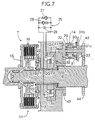
- the power transmission system T which is placed between the driving shaft 5 which rotates in operative connection with the rotation of the front wheels Wf, Wf and the driven shaft 6 which rotates in operative connection with the rotation of the rear wheels Wr, Wr comprises a multiple disk clutch 11, a torque cam mechanism 12, a hydraulic pump 13 and a bidirectional clutch mechanism 14 which are placed in that order from the driving shaft 5 side to the driven shaft 6 side.
- the multiple disk clutch 11 governs the transmission and blocking of torque between the driving shaft 5 and the driven shaft 6 and is formed by alternately superimposing a plurality of frictional engagement members 16 ⁇ supported on a clutch outer 15 which rotates together with the driving shaft 5 and a plurality of frictional engagement members 18 ⁇ supported on a clutch inner 17 which rotates together with the driven shaft 5, and the two frictional engagement members 16 ⁇ , 18 ⁇ come into close contact with each other by receiving a thrust force from the torque cam mechanism 12, which is described hereinafter so as to engage the driving shaft 5 with the driven shaft 6.
- the torque cam mechanism 12 comprises a first cam element 19 which is connected by splines to the clutch outer 15 and a second cam element 21 which is connected to the forward end of a sleeve 20 coaxially fitted around an outer circumference of the driven shaft 6, and a plurality of balls 22 ⁇ are supported between the plurality of triangular cam channels 19a ⁇ , 21a ⁇ which are formed on the surfaces of the first cam element 19 and the second cam element 21, respectively, that face each other.
- the hydraulic pump 13 comprises a first port 13a and a second port 13b; when the first rotor 23 and the second rotor 24 rotate relative to each other in one direction the hydraulic oil which is taken in through the first port 13a discharges into the second port 13b, and when the first rotor 23 and the second rotor 24 rotate relative to each other in the other direction the hydraulic oil which is taken in through the second port 13b discharges into the first port 13a.
- a hydraulic circuit 25 which is connected to the hydraulic pump 13 is formed by connecting in parallel an orifice 26 which is placed between the first port 13a and the second port 13b, a relief valve 27 which opens when the oil pressure of the first port 13a exceeds the oil pressure of the second port 13b by a predetermined value, and a relief valve 28 which opens when the oil pressure of the second port 13b exceeds the oil pressure of the first port 13a by a predetermined value.
- the first clutch element 29 of the bidirectional clutch mechanism 14 rotates by being connected to the second rotor 24 of the hydraulic pump 13, the second clutch element 30 rotates by being connected to the rear wheels Wr, Wr via the driven shaft 6, and at this stage since the rotational rate of the front wheels Wf, Wf coincides with the rotational rate of the rear wheels Wr, Wr, the first and second clutch elements 29, 30 of the bidirectional clutch mechanism 14 rotate in the same direction at the same speed, thereby, bringing about a slip state in which no torque is transmitted.
- the front wheels Wf, Wf slip a proportion of the torque of the above-mentioned front wheels Wf, Wf is distributed to the rear wheels Wr, Wr so putting the vehicle in a four-wheel drive state, and the ground covering properties of the vehicle can be improved.
- the level of torque distributed to the rear wheels Wr, Wr can be increased according to the increase in the difference between the rotational rate of the front wheels Wf, Wf and that of the rear wheels Wr, Wr, that is to say, according to the increase in the degree of slip of the front wheels Wf, Wf.
- the torque transmission from the front wheels Wf, Wf to the rear wheels Wr, Wr is carried out by the multiple disk clutch 11, only a small amount of the torque which is applied between the first and second cam elements 19, 21 of the torque cam mechanism 12 is transmitted to the bidirectional clutch mechanism 14 and, therefore, not only can the size and weight be reduced by using the bidirectional clutch mechanism 14 having a small torque transmission capacity, but the durability can also be enhanced.
- first clutch element 29 of the bidirectional clutch mechanism 14 can rotate at a rotational rate less than that of the second clutch element 30 without receiving any load from the second clutch element 30, rotation of the second rotor 24 of the hydraulic pump 13, which is connected to the second clutch element 30, is not restrained, and the first rotor 23 and the second rotor 24 of the hydraulic pump 13 therefore rotate at the same speed in a state in which no load is being applied.
- first cam element 19 and the second cam element 21 of the torque cam mechanism 12 rotate in the same phase without transmitting any torque, and because no thrust force for engaging the multiple disk clutch 11 is generated the vehicle is maintained in a two-wheel drive state.
- the bidirectional clutch mechanism 14 is not engaged when the vehicle is travelling backward at a constant speed where the rotational rates Nf, Nr of the first clutch element 29 and the second clutch element 30 coincide with each other, and when the vehicle is braked while travelling backward where the rotational rate Nf of the first clutch element 29 becomes less than the rotational rate Nr of the second clutch element 30 and the first clutch element 29 can rotate without a load, the second rotor 24 of the hydraulic pump 13, which is connected to the first clutch element 29, can rotate without a load. Therefore, no torque is transmitted between the first cam element 19 and the second cam element 21 of the torque cam mechanism 12, and the multiple disk clutch 11 is disengaged so as to maintain a two-wheel drive state.
- the second embodiment differs from the aforementioned first embodiment in terms of the layout of the bidirectional clutch mechanism 14. That is to say, in the first embodiment the bidirectional clutch mechanism 14 is placed coaxially on the driven shaft 6, but in the second embodiment the bidirectional clutch mechanism 14 is placed at a position away from the driven shaft 6.
- a gear 41 provided on the first clutch element 29 of the bidirectional clutch mechanism 14 meshes with a gear 42 provided on the second rotor 24 of the hydraulic pump 13, and a gear 43 provided on the second clutch element 30 of the bidirectional clutch mechanism 14 meshes with a gear 44 provided on the driven shaft 6.
- the gear ratio of the two gears 41, 42 on the first clutch element 29 side coincides with the gear ratio of the two gears 43, 44 on the second clutch element 30 side.
- a power generator 45 is used as the load generating means instead of the hydraulic pump 13 of the first embodiment.
- the power generator 45 comprises a first rotor 46 which forms a power generator rotor on the inner side thereof and a second rotor 47 which forms a stator on the outer side thereof; the first rotor 46 is connected to the second cam element 21 of the torque cam mechanism 12 via the sleeve 20, and the second rotor 47 is connected to the first clutch element 29 of the bidirectional clutch mechanism 14. Both ends of the coil of the second rotor 47 are connected to a controller 48.
- the structure of the bidirectional clutch mechanism 14 is not limited to that described in the embodiments, and rollers may be used instead of the sprags 32.
Landscapes
- Engineering & Computer Science (AREA)
- Chemical & Material Sciences (AREA)
- Combustion & Propulsion (AREA)
- Transportation (AREA)
- Mechanical Engineering (AREA)
- Arrangement And Driving Of Transmission Devices (AREA)
- Arrangement And Mounting Of Devices That Control Transmission Of Motive Force (AREA)
Applications Claiming Priority (2)
| Application Number | Priority Date | Filing Date | Title |
|---|---|---|---|
| JP34527899 | 1999-12-03 | ||
| JP34527899A JP3934838B2 (ja) | 1999-12-03 | 1999-12-03 | 四輪駆動車両の動力伝達装置 |
Publications (3)
| Publication Number | Publication Date |
|---|---|
| EP1106415A2 EP1106415A2 (en) | 2001-06-13 |
| EP1106415A3 EP1106415A3 (en) | 2003-05-14 |
| EP1106415B1 true EP1106415B1 (en) | 2005-01-12 |
Family
ID=18375517
Family Applications (1)
| Application Number | Title | Priority Date | Filing Date |
|---|---|---|---|
| EP00126098A Expired - Lifetime EP1106415B1 (en) | 1999-12-03 | 2000-11-29 | Power transmission system for four-wheel drive vehicles |
Country Status (8)
| Country | Link |
|---|---|
| US (1) | US6422365B2 (ja) |
| EP (1) | EP1106415B1 (ja) |
| JP (1) | JP3934838B2 (ja) |
| KR (1) | KR100393690B1 (ja) |
| CN (1) | CN1116994C (ja) |
| CA (1) | CA2327077C (ja) |
| DE (1) | DE60017346T2 (ja) |
| TW (1) | TW472006B (ja) |
Families Citing this family (16)
| Publication number | Priority date | Publication date | Assignee | Title |
|---|---|---|---|---|
| JP4216975B2 (ja) * | 1999-12-03 | 2009-01-28 | 本田技研工業株式会社 | 四輪駆動車両の動力伝達装置 |
| CA2370069C (en) * | 2001-02-05 | 2009-06-02 | Honda Giken Kogyo Kabushiki Kaisha | Vehicular two-wheel drive and four-wheel drive switching system |
| JP3828782B2 (ja) * | 2001-11-08 | 2006-10-04 | 本田技研工業株式会社 | トルクカム機構 |
| US6827664B2 (en) * | 2001-11-15 | 2004-12-07 | General Motors Corporation | Transmission |
| DE10260196A1 (de) * | 2002-12-20 | 2004-07-01 | Bayerische Motoren Werke Ag | Verfahren zum Steuern einer schaltbaren Kupplung in einem Antriebsstrang eines Kraftfahrzeugs mit Vierradantrieb |
| EP1662978B1 (en) * | 2003-09-18 | 2013-05-29 | Howmedica Osteonics Corp. | Surgical retractor |
| JP4271001B2 (ja) * | 2003-10-16 | 2009-06-03 | 本田技研工業株式会社 | 四輪駆動車両の動力伝達装置 |
| US6971494B2 (en) * | 2004-01-13 | 2005-12-06 | Magna Drivetrain Of America, Inc. | Torque transfer coupling with friction clutch and hydraulic clutch actuator |
| US6948604B2 (en) * | 2004-01-30 | 2005-09-27 | Magna Drivetrain Of America, Inc. | Hydraulically-actuated pilot clutch type clutch assembly |
| US6945374B2 (en) * | 2004-02-04 | 2005-09-20 | Magna Drivetrain Of America, Inc. | Active torque coupling with hydraulically-actuated ball ramp clutch assembly |
| WO2006044991A2 (en) * | 2004-10-19 | 2006-04-27 | Magna Powertrain Usa, Inc. | Torque transfer mechanisms with power-operated clutch actuator |
| EP1833379B1 (en) * | 2005-01-07 | 2016-08-24 | Stryker European Holdings I, LLC | Three-prong retractor with elastomeric sheath |
| US20090211872A1 (en) * | 2008-02-14 | 2009-08-27 | Youngwerth Albert J | Apparatus and system for a torque responsive clutch |
| JP5900023B2 (ja) * | 2012-03-02 | 2016-04-06 | 三菱自動車工業株式会社 | ハイブリッド車用トランスアクスル装置 |
| JP6412678B2 (ja) * | 2012-12-06 | 2018-10-24 | 株式会社ジェイテクト | 駆動力伝達制御装置 |
| US11146157B2 (en) | 2018-05-03 | 2021-10-12 | Schaeffler Technologies AG & Co. KG | Dual rotor electric machine in an automotive application |
Family Cites Families (8)
| Publication number | Priority date | Publication date | Assignee | Title |
|---|---|---|---|---|
| US5203232A (en) * | 1991-02-18 | 1993-04-20 | Ntn Corporation | Rotation transmitting device |
| US5595214A (en) * | 1993-02-10 | 1997-01-21 | Asha Corporation | Hydraulic coupling for vehicle drivetrain |
| US5584776A (en) * | 1995-03-24 | 1996-12-17 | Borg-Warner Automotive, Inc. | Transfer case having parallel clutches and lockup feature |
| JPH09202152A (ja) * | 1996-01-26 | 1997-08-05 | Ntn Corp | 4輪駆動車の回転伝達装置 |
| US5884738A (en) * | 1997-04-30 | 1999-03-23 | Borg-Warner Automotive, Inc. | Clutch assembly having reaction force circuit |
| US5915513A (en) * | 1997-08-26 | 1999-06-29 | Borg-Warner Automotive, Inc. | Clutch with magneto-rheological operator for transfer cases and the like |
| US6062361A (en) * | 1998-11-03 | 2000-05-16 | Borg-Warner Automotive, Inc. | Acceleration sensitive double overrunning clutch |
| JP2000230575A (ja) * | 1998-12-10 | 2000-08-22 | Nsk Warner Kk | 摩擦係合装置 |
-
1999
- 1999-12-03 JP JP34527899A patent/JP3934838B2/ja not_active Expired - Fee Related
-
2000
- 2000-11-28 TW TW089125251A patent/TW472006B/zh not_active IP Right Cessation
- 2000-11-29 DE DE60017346T patent/DE60017346T2/de not_active Expired - Lifetime
- 2000-11-29 CA CA002327077A patent/CA2327077C/en not_active Expired - Fee Related
- 2000-11-29 EP EP00126098A patent/EP1106415B1/en not_active Expired - Lifetime
- 2000-11-30 US US09/725,937 patent/US6422365B2/en not_active Expired - Fee Related
- 2000-12-01 CN CN00134457A patent/CN1116994C/zh not_active Expired - Fee Related
- 2000-12-04 KR KR10-2000-0072830A patent/KR100393690B1/ko not_active IP Right Cessation
Also Published As
| Publication number | Publication date |
|---|---|
| US20010002629A1 (en) | 2001-06-07 |
| KR20010062104A (ko) | 2001-07-07 |
| CA2327077A1 (en) | 2001-06-03 |
| JP2001158255A (ja) | 2001-06-12 |
| DE60017346D1 (de) | 2005-02-17 |
| CN1298816A (zh) | 2001-06-13 |
| EP1106415A2 (en) | 2001-06-13 |
| CN1116994C (zh) | 2003-08-06 |
| KR100393690B1 (ko) | 2003-08-06 |
| DE60017346T2 (de) | 2005-06-02 |
| JP3934838B2 (ja) | 2007-06-20 |
| EP1106415A3 (en) | 2003-05-14 |
| TW472006B (en) | 2002-01-11 |
| CA2327077C (en) | 2004-09-14 |
| US6422365B2 (en) | 2002-07-23 |
Similar Documents
| Publication | Publication Date | Title |
|---|---|---|
| EP1106415B1 (en) | Power transmission system for four-wheel drive vehicles | |
| US7562947B2 (en) | Apparatus for controlling driving force of vehicle | |
| EP1303420B1 (en) | Vehicle transmission systems | |
| JP3713717B2 (ja) | 自動車用トルク・トランスファ・ケース | |
| AU2001269342A1 (en) | Vehicle transmission systems | |
| US4185723A (en) | Automatic four-wheel drive transfer case | |
| US4098379A (en) | Automatic four-wheel drive transfer case | |
| EP1494886B1 (en) | Vehicle transmission system | |
| US7422537B2 (en) | Torque split hydraulic coupling between transmission and secondary driving axle with torque modulation and locking capabilities | |
| JP2675413B2 (ja) | 4輪駆動装置 | |
| JP3340038B2 (ja) | 左右輪駆動力配分装置 | |
| JP4216975B2 (ja) | 四輪駆動車両の動力伝達装置 | |
| JP2979878B2 (ja) | 車両用左右駆動力調整装置 | |
| JP3565566B2 (ja) | 4輪駆動車用駆動力配分装置 | |
| JP4418076B2 (ja) | トランスファ装置 | |
| JP2528006B2 (ja) | 4輪駆動車の動力配分装置 | |
| JPH09202152A (ja) | 4輪駆動車の回転伝達装置 | |
| RU2271284C2 (ru) | Антиблокировочная система автотранспортных средств | |
| KR20230028173A (ko) | 유성기어 타입의 동력전달 제어장치 | |
| WO1984001608A1 (en) | Differential mechanisms | |
| JPH07332402A (ja) | 4輪駆動用駆動連結装置 | |
| JPS6130423A (ja) | 四輪駆動用横置トランスミツシヨン | |
| JP2014008785A (ja) | 四輪駆動車両のトルク伝達装置 | |
| JPH03177625A (ja) | ビスカスカップリング | |
| JPH08268101A (ja) | 差動制限解除装置 |
Legal Events
| Date | Code | Title | Description |
|---|---|---|---|
| PUAI | Public reference made under article 153(3) epc to a published international application that has entered the european phase |
Free format text: ORIGINAL CODE: 0009012 |
|
| AK | Designated contracting states |
Kind code of ref document: A2 Designated state(s): AT BE CH CY DE DK ES FI FR GB GR IE IT LI LU MC NL PT SE TR |
|
| AX | Request for extension of the european patent |
Free format text: AL;LT;LV;MK;RO;SI |
|
| PUAL | Search report despatched |
Free format text: ORIGINAL CODE: 0009013 |
|
| AK | Designated contracting states |
Designated state(s): AT BE CH CY DE DK ES FI FR GB GR IE IT LI LU MC NL PT SE TR |
|
| AX | Request for extension of the european patent |
Extension state: AL LT LV MK RO SI |
|
| 17P | Request for examination filed |
Effective date: 20030617 |
|
| AKX | Designation fees paid |
Designated state(s): DE FR GB |
|
| GRAP | Despatch of communication of intention to grant a patent |
Free format text: ORIGINAL CODE: EPIDOSNIGR1 |
|
| GRAS | Grant fee paid |
Free format text: ORIGINAL CODE: EPIDOSNIGR3 |
|
| GRAA | (expected) grant |
Free format text: ORIGINAL CODE: 0009210 |
|
| AK | Designated contracting states |
Kind code of ref document: B1 Designated state(s): DE FR GB |
|
| REG | Reference to a national code |
Ref country code: GB Ref legal event code: FG4D |
|
| REF | Corresponds to: |
Ref document number: 60017346 Country of ref document: DE Date of ref document: 20050217 Kind code of ref document: P |
|
| REG | Reference to a national code |
Ref country code: IE Ref legal event code: FG4D |
|
| PLBE | No opposition filed within time limit |
Free format text: ORIGINAL CODE: 0009261 |
|
| STAA | Information on the status of an ep patent application or granted ep patent |
Free format text: STATUS: NO OPPOSITION FILED WITHIN TIME LIMIT |
|
| PGFP | Annual fee paid to national office [announced via postgrant information from national office to epo] |
Ref country code: GB Payment date: 20051123 Year of fee payment: 6 |
|
| ET | Fr: translation filed | ||
| 26N | No opposition filed |
Effective date: 20051013 |
|
| PG25 | Lapsed in a contracting state [announced via postgrant information from national office to epo] |
Ref country code: FR Free format text: LAPSE BECAUSE OF NON-PAYMENT OF DUE FEES Effective date: 20060731 |
|
| REG | Reference to a national code |
Ref country code: FR Ref legal event code: ST Effective date: 20060731 |
|
| GBPC | Gb: european patent ceased through non-payment of renewal fee |
Effective date: 20061129 |
|
| PG25 | Lapsed in a contracting state [announced via postgrant information from national office to epo] |
Ref country code: GB Free format text: LAPSE BECAUSE OF NON-PAYMENT OF DUE FEES Effective date: 20061129 |
|
| PGFP | Annual fee paid to national office [announced via postgrant information from national office to epo] |
Ref country code: DE Payment date: 20091126 Year of fee payment: 10 |
|
| REG | Reference to a national code |
Ref country code: DE Ref legal event code: R119 Ref document number: 60017346 Country of ref document: DE Effective date: 20110601 Ref country code: DE Ref legal event code: R119 Ref document number: 60017346 Country of ref document: DE Effective date: 20110531 |
|
| PG25 | Lapsed in a contracting state [announced via postgrant information from national office to epo] |
Ref country code: DE Free format text: LAPSE BECAUSE OF NON-PAYMENT OF DUE FEES Effective date: 20110531 |