EP1099885A2 - Stufenloses Getriebe und Steuerungssystem für die elastische Klemmkraft - Google Patents
Stufenloses Getriebe und Steuerungssystem für die elastische Klemmkraft Download PDFInfo
- Publication number
- EP1099885A2 EP1099885A2 EP00124597A EP00124597A EP1099885A2 EP 1099885 A2 EP1099885 A2 EP 1099885A2 EP 00124597 A EP00124597 A EP 00124597A EP 00124597 A EP00124597 A EP 00124597A EP 1099885 A2 EP1099885 A2 EP 1099885A2
- Authority
- EP
- European Patent Office
- Prior art keywords
- pressurizing
- pressure
- elastic
- pulley
- elastic member
- Prior art date
- Legal status (The legal status is an assumption and is not a legal conclusion. Google has not performed a legal analysis and makes no representation as to the accuracy of the status listed.)
- Granted
Links
- 230000005540 biological transmission Effects 0.000 title claims abstract description 131
- 230000006835 compression Effects 0.000 claims abstract description 85
- 238000007906 compression Methods 0.000 claims abstract description 85
- 238000011022 operating instruction Methods 0.000 claims description 68
- 230000001276 controlling effect Effects 0.000 claims description 36
- 230000006866 deterioration Effects 0.000 claims description 33
- 238000003860 storage Methods 0.000 claims description 28
- 238000006243 chemical reaction Methods 0.000 claims description 19
- 238000012545 processing Methods 0.000 claims description 18
- 230000002441 reversible effect Effects 0.000 claims description 10
- 238000004519 manufacturing process Methods 0.000 claims description 9
- 230000004044 response Effects 0.000 claims description 8
- 230000001965 increasing effect Effects 0.000 claims description 7
- 230000001105 regulatory effect Effects 0.000 claims description 6
- 230000008054 signal transmission Effects 0.000 claims description 4
- 230000003247 decreasing effect Effects 0.000 claims description 3
- 230000036961 partial effect Effects 0.000 claims description 2
- 238000006073 displacement reaction Methods 0.000 description 32
- 230000008859 change Effects 0.000 description 17
- 230000002829 reductive effect Effects 0.000 description 12
- 238000005728 strengthening Methods 0.000 description 11
- 239000012530 fluid Substances 0.000 description 8
- 230000007246 mechanism Effects 0.000 description 7
- 230000009467 reduction Effects 0.000 description 7
- 238000010276 construction Methods 0.000 description 6
- 230000007423 decrease Effects 0.000 description 6
- 238000013461 design Methods 0.000 description 5
- 238000001514 detection method Methods 0.000 description 5
- 238000000034 method Methods 0.000 description 5
- 238000004804 winding Methods 0.000 description 5
- 239000004148 curcumin Substances 0.000 description 4
- 230000000694 effects Effects 0.000 description 4
- 230000008569 process Effects 0.000 description 4
- 230000001360 synchronised effect Effects 0.000 description 4
- 230000008901 benefit Effects 0.000 description 3
- 230000008602 contraction Effects 0.000 description 3
- 230000002093 peripheral effect Effects 0.000 description 3
- 238000003825 pressing Methods 0.000 description 3
- 230000035939 shock Effects 0.000 description 3
- 239000002131 composite material Substances 0.000 description 2
- 238000009434 installation Methods 0.000 description 2
- 239000000463 material Substances 0.000 description 2
- 239000002184 metal Substances 0.000 description 2
- 229910052751 metal Inorganic materials 0.000 description 2
- 230000004043 responsiveness Effects 0.000 description 2
- 238000000638 solvent extraction Methods 0.000 description 2
- 230000006641 stabilisation Effects 0.000 description 2
- 238000011105 stabilization Methods 0.000 description 2
- 230000001629 suppression Effects 0.000 description 2
- 208000032369 Primary transmission Diseases 0.000 description 1
- 208000032370 Secondary transmission Diseases 0.000 description 1
- 230000001133 acceleration Effects 0.000 description 1
- 230000009471 action Effects 0.000 description 1
- 230000002411 adverse Effects 0.000 description 1
- 238000012937 correction Methods 0.000 description 1
- 230000007547 defect Effects 0.000 description 1
- 230000007850 degeneration Effects 0.000 description 1
- 230000002708 enhancing effect Effects 0.000 description 1
- 238000012423 maintenance Methods 0.000 description 1
- 150000002739 metals Chemical class 0.000 description 1
- 230000004048 modification Effects 0.000 description 1
- 238000012986 modification Methods 0.000 description 1
- 230000003449 preventive effect Effects 0.000 description 1
- 239000004065 semiconductor Substances 0.000 description 1
Images




Classifications
-
- F—MECHANICAL ENGINEERING; LIGHTING; HEATING; WEAPONS; BLASTING
- F16—ENGINEERING ELEMENTS AND UNITS; GENERAL MEASURES FOR PRODUCING AND MAINTAINING EFFECTIVE FUNCTIONING OF MACHINES OR INSTALLATIONS; THERMAL INSULATION IN GENERAL
- F16H—GEARING
- F16H61/00—Control functions within control units of change-speed- or reversing-gearings for conveying rotary motion ; Control of exclusively fluid gearing, friction gearing, gearings with endless flexible members or other particular types of gearing
- F16H61/66—Control functions within control units of change-speed- or reversing-gearings for conveying rotary motion ; Control of exclusively fluid gearing, friction gearing, gearings with endless flexible members or other particular types of gearing specially adapted for continuously variable gearings
- F16H61/662—Control functions within control units of change-speed- or reversing-gearings for conveying rotary motion ; Control of exclusively fluid gearing, friction gearing, gearings with endless flexible members or other particular types of gearing specially adapted for continuously variable gearings with endless flexible members
- F16H61/66272—Control functions within control units of change-speed- or reversing-gearings for conveying rotary motion ; Control of exclusively fluid gearing, friction gearing, gearings with endless flexible members or other particular types of gearing specially adapted for continuously variable gearings with endless flexible members characterised by means for controlling the torque transmitting capability of the gearing
-
- F—MECHANICAL ENGINEERING; LIGHTING; HEATING; WEAPONS; BLASTING
- F16—ENGINEERING ELEMENTS AND UNITS; GENERAL MEASURES FOR PRODUCING AND MAINTAINING EFFECTIVE FUNCTIONING OF MACHINES OR INSTALLATIONS; THERMAL INSULATION IN GENERAL
- F16H—GEARING
- F16H55/00—Elements with teeth or friction surfaces for conveying motion; Worms, pulleys or sheaves for gearing mechanisms
- F16H55/32—Friction members
- F16H55/52—Pulleys or friction discs of adjustable construction
- F16H55/56—Pulleys or friction discs of adjustable construction of which the bearing parts are relatively axially adjustable
-
- F—MECHANICAL ENGINEERING; LIGHTING; HEATING; WEAPONS; BLASTING
- F16—ENGINEERING ELEMENTS AND UNITS; GENERAL MEASURES FOR PRODUCING AND MAINTAINING EFFECTIVE FUNCTIONING OF MACHINES OR INSTALLATIONS; THERMAL INSULATION IN GENERAL
- F16H—GEARING
- F16H63/00—Control outputs from the control unit to change-speed- or reversing-gearings for conveying rotary motion or to other devices than the final output mechanism
- F16H63/02—Final output mechanisms therefor; Actuating means for the final output mechanisms
- F16H63/04—Final output mechanisms therefor; Actuating means for the final output mechanisms a single final output mechanism being moved by a single final actuating mechanism
- F16H63/06—Final output mechanisms therefor; Actuating means for the final output mechanisms a single final output mechanism being moved by a single final actuating mechanism the final output mechanism having an indefinite number of positions
- F16H63/062—Final output mechanisms therefor; Actuating means for the final output mechanisms a single final output mechanism being moved by a single final actuating mechanism the final output mechanism having an indefinite number of positions electric or electro-mechanical actuating means
Definitions
- the present invention relates to a pulley press controlling apparatus using an elastic member in which a pressurizing force and an elastic force corresponding thereto are always simultaneously applied from outside to a frictional transmission surface between a pulley and a belt transmission in a continuously variable speed transmission or a constant speed ratio transmission to stably maintain the accuracy of the elastic press and so on over a long period of time.
- the elastic force of the elastic member merely comprises the direct proportional characteristic D. Accordingly, this means that the elastic force is applied to the pressurizing force merely by a point of intersection F between the characteristics A and D, but in points other than the point of intersection F, the elastic force rarely contributes to transmission.
- the fact that the elastic force is not present in the frictional transmission surface despite the presence or absence of variable speed indicates that the momentary return into the stable transmission caused by the self settling function for pressurizing and absorbing shock vibrations between the pulley and the belt and the automatic aligning function fails to be achieved. Therefore, since in the frictional transmission surface, the state of surplus press or lack in press is repeated every disturbance, there poses a disadvantage that consumption of the frictional surface is accelerated, resulting in disablement of transmission in a short period of time.
- the present applicant has made a proposal, in Japanese Patent Application No. Hei 10 (1998) - 321246, in which an elastic pressurizing force generated by pressurizing a compression device and an elastic device in series with each other is applied to a secondary pulley.
- positive application of the elastic force of the elastic member to the friction transmission causes an advantage and a disadvantage present simultaneously.
- the advantage includes stabilization of transmission for a long period of time, and high-speed control responsiveness.
- the disadvantage includes a huge dimension of and a large-size of the elastic member, disturbance of process accuracy in manufacture of compression displacement to pressurizing force, variation of pressurizing characteristic caused by deformation and deterioration in order to maintain repeated compression and high load compression, and ambient temperature.
- the huge dimension can be solved by measures such as the use of a special high load elastic member or the arrangement of the elastic member in a non-rotational state, but the disturbance of the elastic pressurizing force generated from the pressurizing device itself brings forth instability of direct frictional transmission and degeneration of efficiency. Accordingly, it has been strongly expected that the pressurizing force and the revolution number are applied to the elastic pressurizing device having the elastic member and the non-elastic pressurizing device using the negative measures for applying restoring compensation of an error in pressurizing force caused by manufacturing or use of high load and already generated to a proper value, and the positive measures for applying function adjustment for further accelerating and strengthening utility of an elastic member during transmission or during stoppage.
- a fundamental solution of the present invention is to provide a pulley press controlling apparatus using an elastic member in which a pressurizing device always applies an elastic pressurizing force to a pulley, and always controls it to a predetermined desired pressurizing force selected value with the compensation of an error in pressurizing force of the elastic pressurizing force and/or the adjustment of pressurizing function to stably maintain and strengthen the utility function of the elastic pressurizing force of the elastic member in a long period of time.
- an error in pressure of an elastic pressurizing force caused by the manufacturing and processing accuracy of a pressurizing device having an elastic member and the peripheral temperature of installation and caused by the deformation and deterioration of the elastic member under the repeated compression or high compression for a long period of time is restored and compensated to always apply an elastic pressurizing force of high accuracy.
- a desired selected value of an elastic pressurizing force applied by an elastic member is applied with fine adjustment during transmission operation to forcibly change the efficiency of transmission or safety rate, or applied with extremely low reduction adjustment positively during stoppage of transmission to forcibly release or suppress the compression state for a long period of time to thereby apply strengthening adjustment of utility function of the elastic member substantially.
- restoring compensation of an error in pressure of an elastic pressurizing force and adjustment for strengthening a pressurizing force by forcibly reducing the pressurizing force selected value are combined so that operating information of restoring compensation is taken in at the time of the strengthening adjusting operation in the process of applying pressure to or releasing pressure from the elastic member to effect operation processing to newly execute pressure error compensation for variable speed or press control.
- a pressurizing device when a pressurizing device operates in variable speed a pulley under non-elastic pressurizing force, an error in revolution number of a secondary pulley caused by a deformation and deterioration of belt dimension is compensated by the procedure similar to that taken for the error in pressurizing force.
- a control device since a pulley added an elastic force controls an output torque based on a belt frictional force and a pulley added a non-elastic force controls an output revolution number, a control device provides operating instructions to the operating devices by dealing with various informations collectively and so simplicity and reliability of control manipulation are achieved.
- an elastic force supplying pulley can control the torque by a belt friction force
- non-elastic force pressure supplying pulley can control the revolution number, respectively so that the respective operating instructions may be processed in the lump to supply the informations to each operating device independently, and thereby simplifying and accelerating the control operation.
- said control device causes said processing unit to increase and decrease the compensation amount corresponding to said deviation amount from the input operating instruction in order to make said deviation substantially zero to convert it into the pressure operating instruction, whereby a pressure error of said elastic pressurizing force in said pressurizing device is restored and compensated.
- said control device causes said storage device to fine-adjust the desired selected value of said elastic pressurizing force during a period of transmission operation or transmission stop of said transmission device in order to forcibly enhance the efficiency or the safety rate with respect to frictional transmission, or to store in advance the adjustment amount for the reduction adjustment in order to suppress deterioration from high compression of the elastic member, and said processing unit forcibly increases an decreases said adjustment amount from the input operating instruction to convert it into the pressure operating instruction to impart a strengthening function to said pressurizing device.
- the error restoring compensation of the elastic pressurizing force and the forcible reduction adjustment of said elastic pressurizing force selected value in order to suppress deterioration of the elastic member are carried out, and the restoring compensation of the pressure error of said elastic pressurizing force is executed when said adjusting operation takes place to update the compensation amount when the transmission operation newly takes place for the high accuracy control.
- the compensation amount according to the deviation between a detected value of the revolution number of the secondary pulley or the speed ration of the transmission and a predetermined selected value of the output revolution number detector of said pulley or the speed ratio detector is applied to the pressure operating instruction.
- the fifth means for solving a problem in this invention is to arrange the first and second drive sources independently connected to the first and second pressurizing devices, and thereby the operating instructions signal- processed on the side of the control device are supplied directly or indirectly.
- the present invention is not limited merely to the wet type transmission device of a constant horse power transmission type having a large capacity for use with vehicles, but the present idea can be also applied to general industrial machineries having a small capacity as well as the dry type variable speed transmission irrespective of capacity.
- the present invention makes of merits and demerits of the elastic device and the belt when the high pressurizing force generated by compressing the elastic device in series is applied to the pulley and the belt, and so, the present idea may be applied to the constitution that one of the pulleys holds the belt between two disks, and the other pulley is of not only the similar variable speed sheave but also the constant speed ratio sheaves of other types, and to a mere constant speed ratio transmission device.
- the constant horse power transmission and the constant torque transmission can be achieved easily in a single machine. Also in this case, the frictional torque and revolution number of the secondary pulley can be maintained with high accuracy for a long period of time by the compensation measures and adjustment measures similar to the present example.
- a tension type belt may be used instead of the compression type of the present embodyment.
- the program control termed in the present invention includes a conception of a recent programmable control (PLC), in which adjustment and control are sequentially done in accordance with the change in a pressurizing force selected value programmed in advance in a storage device according to the change in the input manipulated variable.
- PLC programmable control
- the generated error of the pressurizing force results from various causes such as the deformation and deterioration of the elastic member or the belt, the error when materials or the like are manufactured, and peripheral temperature for use. To collectively restore them by one compensation, it is necessary to widely design the sliding displacement amount of the compression device in advance since the pressurizing device changes in zero and span positions.
- the elastic device may be added only one of the safety rate and the efficiency during the transmission operation as the strengthening adjustment, and may be applied with the additional function for applying the pressurizing force in excess of the maximum pressure Pmax or not more than the minimum pressure Pmin in the secondary pulley single shaft torque control mode.
- the pressure detector may convert the pressurizing force into other state amounts such as a position change other than the fluid pressure.
- the single pressurizing with respect to the secondary pulley through the elastic device itself is possible during transmission operation or stoppage of the transmission unlike the primary pulley, and can be applied irrespective of the primary pulley and independently.
- the pressurizing force can be reduced in the high speed rotational region. Therefore, where the elastic device or the belt can substantially suppress the settling deterioration or the deformation and deterioration even in the reduction state, it can be utilized as the substantial compression releasing measures of the elastic member according to the operating instruction.
- the elastic pressurizing force of the pressurizing device may be applied between the pulley and the main body, arrangement order and locations of the elastic device and the compression device therebetween can be suitably changed according to the design, and where they are placed in the non-rotational state in terms of operation, rotation separating bearings may be disposed between the pulley, the compression device, the elastic device, and the main body.
- the elastic device and the compression device are present a slider, a sliding unit, and a pressure transmission device as similar members, which may be jointly used with other members or subdivided and may be replaced by members such as disks of the pulley, and the main body according to the design.
- suitable changes are included in the scope of the present invention as long as they remains in mere selection and design of members.
- the elastic device may be of a single elastic member, a kind of which is not limited to a wavy plate-like spring such as a dish spring but other forms such as a coil spring may be employed.
- compression forms of the elastic deice are not limited to the continuous linear pressurizing characteristic by way of the simultaneous drive of a plurality of springs juxtaposed concentrically, but the pressurizing characteristic may be of the non-continuous stepwise characteristic by individually urging the respective elastic members with respect to the compression displacement, or of the non-linear continuous curve characteristic. Correction adjustment and compelled adjustment of an error in manufacture and an error in deterioration of the elastic member are simple measures in the case where the pressurizing characteristic is the linear characteristic.
- the compression device may be a normal trapezoidal screw, and is not limited to a winding sliding mechanism comprising a displacement mechanism for converting rotation to sliding like a rotational cam, but a fluid pressurizing and sliding mechanism like a hydraulic cylinder may be employed.
- a driving source may be an electric type or a fluid pressure type, and the installation place may be also a non-coaxial position or, rotational or non-rotational is available.
- a compression displacement amount L o3 of the elastic member itself may be provided separately.
- the displacement amount L o on the secondary pulley side required is about two times or so of the displacement amount L 1 on the primary pulley side. Since the rotational operating direction as well as the operating amount are different according to the respective cases, well-known elements such as a winding pitch, a rotational direction, a revolution number of the compression devices, or a pressurizing direction of a threaded groove (right-hand thread, left-hand thread), and a speed ratio of the gear transmission may be suitably selected according to the design.
- an AC or DC servo motor provided with an error signal transmission impeding means having self-lock functions of a reversible motor, that is, an anti-rotation brake mechanism and an anti-overrun function, but when the step motor itself performs the function of the preventive means, an open-loop drive may be done.
- a reversible motor that is, an anti-rotation brake mechanism and an anti-overrun function
- an open-loop drive may be done.
- a frictional resistance of metals surfaces is well-known to have such a self-lock function in itself.
- mechanical motors such as fluid or hydraulic motors may be applied.
- FIGS. 1 to 9 show constructions of parts and a pressurizing device of, as one example, a continuously variable speed transmission for vehicles to which a pulley press controlling apparatus using an elastic member according to a first embodiment of the present invention is applied.
- a variable speed transmission device 10 comprises, as a fundamental constitution, a variable speed transmission device 10a comprising a primary transmission wheel or a primary pulley 2, a secondary transmission wheel or a secondary pulley 1, and a belt 11 extended over and between both the pulleys; and a variable speed control device 10b comprising a secondary operating unit 6 on the side of the secondary pulley 1 for variable-speed controlling the pulleys 1, 2, a primary operating unit 8 on the side of the primary pulley 2, an operating device 9 including operating device 9a, 9b for synchronously or non-synchronously driving both the operating units 6, 8, and a control device 69.
- the operating device 9 comprises two driving sources 60a, 60b.
- the primary operating unit 8 is energized by the driving source 60b and a pressurizing device 8', and the secondary operating unit 6 is energized by a pressurizing device 5 comprising an elastic device 3 and a compression device 4 for compressing the former and the driving source 60a.
- a pulley press controlling apparatus 7 by an elastic member according to the present embodyment is in the form of the control of the pressurizing device 5, 8' for variably press controlling two of the pulleys 1, 2 which will be described in detail below.
- any of the pulleys 1, 2, sliding disks la, 2a and fixed disks lb, 2b are opposed to each other so that the former are slidably moved relative to the latter through a key, the pulleys 1 and 2 being arranged reversely to each other.
- the operating units 6, 8 for the pulleys 1, 2 control the balance of the pressurizing force from the relative distance between the two disks to continuously change the contact radius r with the belt 11 shown in a compression on type in both the pulleys 1, 2, achieving the power transmission with a fixed horse power in the whole variable speed region.
- a position of the maximum speed ratio is depicted in FIG. 1, while in FIG.
- the transmission device 10 constitutes a wet type speed change gear which forms a closed oil storage chamber comprising a main member 10e and a lid member 10d.
- a compression device 14 of the primary operating unit 8 comprises a sliding device 15 having a winding press device 15a and an urging device 12 for actuating the former.
- the former comprises two sliders 16, 17 formed with ball threads as the press device, while the latter comprises a worm transmission device 12 comprising a worm 18 and a wheel 19.
- a primary shaft 20 is supported by bearings 21, 22.
- a compression device 14 is arranged through bearings 13a, 13b and 23 between a body standard surface 10c and the belt 2. When the slider 16 is turned by the wheel 19, the other slider 17 is not rotated but is pressed and slidably moved only in the axial direction by a guide rod 24a. The winding thread of the compression device 14 is machined into the right-hand thread.
- Numeral 24 designates a pressure transmission device which constitutes a part of the slider 17.
- the pressurizing device 5 of the secondary operating unit 6 is not installed around the sliding disk la but is installed in a non-rotational state on the lid member 10d on the same plane as the primary operating unit 8.
- the pressurizing device 5 comprises two transmitting lever shafts 41a, 41b from a lever 28 branched right and left about the compression device 4 disposed on the same shaft as the secondary pulley rotational shaft, four linear ball bearings 42, 43, and a shifter 44, and is connected to a pressure transmission device 40 for transmitting the pressurizing force via a gimbals 47, a thrust receiver 46, and a bearing 45 disposed on the pulley 1.
- the internal constitution of the pressurizing device 5 shows by way of an example in which the pressurizing forces of the elastic device 3 and the compression device 4 are joined in series with each other with the bearing 31 being a joint point. Accordingly, the elastic pressurizing force of the elastic device 3 is applied, as the composite pressurizing force, in series with the compression device 4 to the pulley 1 via the compression device 4 and the transmission device 40 from the bearing 31 with a bottom lid 36 which is a body standard surface 10c as a standard.
- the elastic device 3 in the present embodiment is in the form of an example of a single construction in which two sides of a plurality of wave-plate like elastic members 33 are alternately combined in series and sandwiched by two sliders 36, 37 and accommodated in advance into a casing 35 in a fixed pressurizing state.
- the elastic device 3 is disposed on the fixed body in a non-rotational state and supported vibrationally at one end and non-vibrationally at the other end, the slider 37 is connected and pressed to the compression device 4, and the slider 36 constitutes a fixed bottom lid.
- the slider 37 compresses the plurality of elastic members 33 as it compresses and presses, and at the same time, transmits the reaction to the secondary pulley 1 from the compression device 4.
- the elastic member 33 comprises 6 well-known dish springs with a inclined part applied in a radial direction, surface-directed springs 33a to 33c, back-directed springs 33d to 33f being alternately opposed in series, and is pressed by a pressurizing element 37a while being guided by a cylindrical guide 37b of the slider 37.
- a semi-circular engaging member 32a formed with openings 32b divided into two sections to house the elastic member 33 with a value in which an initial pressurizing state is in advance equal to or lower than the minimum pressurizing force Ps.
- the compression pressurizing force can be selected suitably according to a series or parallel combination of dish springs.
- a pressure detector 71 is arranged between the elastic device 3 and the bottom lid 36 of the fixed body 10d. Since the whole compression pressurizing force of the elastic member 33 is transmitted to the secondary pulley 1 with the bottom lid being a standard, the pressure detector 71 can detect, as the detection value, the whole pressurizing force to the secondary pulley 1.
- the stopper 38 is provided at the end of the guide 37b of the slider 37, which is connected to the compression device 4 for the compress pressurizing while turning through the bearing 31 to provide transmission of pressure each other. It is noted that the pressure detector 71 may be disposed in other locations if it can detect the whole pressurizing force.
- the elastic device 3 in the present embodiment is connected with the compression device 4 to constitute a detachable single pressurizing device 5, but as described later, it is interposed between a main element, a sliding device 25 of the compression device 4 and an urging device 29 for driving the former, and connected each other via the elastic member 33 of the elastic device 3 and through-holes 30 of the sliders 36, 37.
- the compression device 4 has a sliding device 25 comprising two sliders 26, 27 formed with a ball screw as a press device 25a, and an urging device 29 comprising a worm 48 and a wheel 49 as an anti-inversion self locking mechanism to from an error signal transmission impeding means preventing from a pressure outflow, the elastic device 3 being sandwiched therebetween.
- the slider 26 is formed by a threaded part 26a, a connecting part 26b, a sliding part 26c, and a pressurizing part 26d.
- the sliding part 26c forms a spline shaft, receives only a turning force between it and the wheel 49, transmits the turning force to the threaded part 26a, and is engaged slidably in the axial direction.
- the compression device 4 is assembled integrally with the elastic device 3 secured to the main body 10, and is supported in a levitating or floating state with respect to the secondary pulley 1 and the elastic device 3 to assure the transmission of vibrations therebetween.
- the tubular ball threads applied to the slider 16 of the sliding device 15 of the primary operating unit 8 are processed to have the right hand threads while the rod-like ball threads of the slider 26 of the secondary operating unit 3 are processed to have the left hand threads.
- the slider 27 is applied with a connecting lever 18 having two levers 28a, 28b, and connected to a transmission lever 41 of a pressure transmission device 40.
- the sliding device 25 is supported in a floating state by three points, i.e., a bearing 31 at the extreme end, and two levers 41, and the sliding part 26c has a fixed length for both variable speed displacement and vibration displacement.
- the sliding device 25 is disposed coaxial with the rotational center of the secondary pulley 1, and is dispersively connected by two levers 41a, 41b disposed in parallel right and left from the center shaft, and therefore, the pressure transmission device 40 of a bifurcated branch point construction assures the stability of pressure transmission even with respect to great elastic pressurizing force between the sliding device 25 and the secondary pulley 1. Since at this time, the elastic device 3 is disposed on the fixed body to enable vibration transmission between the sliding device 25 and the secondary pulley 1, both the sliding device 25 and the pressure transmission device 40 are supported in a floating state.
- the elastic device 3 is connected directly to the secondary pulley 1, even if the elastic device 3 itself is supported in a floating state, it directly transfers the vibration force, and therefore, the floating characteristic and the vibration transmission are not necessary for the compression device 4. Also when only one of the elastic device 3 and the compression device 4 is apart at a non-coaxial position while the other is connected to the secondary pulley 1, the pressure transmission device 40 is necessary, but the consideration of the aforementioned floating characteristic and vibration transmission characteristic is the same. In this case, the lever 28 may invert the transmission direction of pressure by the principle of lever.
- the operating device 9 has, in the present embodiment, driving sources 60a, 60b individually to variably drive the secondary pulley 1 and the primary pulley 2 and the respective transmission wheels, is constituted by reversible motors 53a, 53b with gear heads of the same specification, gear heads 53c, 53d, and a gear transmission 63, and is connected to the compression devices 4, 14 of the respective transmission wheels.
- Both the reversible motors 53 is a well-known DC servo motor having a brake and an encoder, to act as an error signal transmitting impeding means preventing from a pressure inflow. It is noted that for the driving source, a single motor may be used in common.
- a control device 69 comprises storage devices 65, 66, a processing unit 70, an input/output unit 68 including a converter such as A/D and D/A converters, a conversion amplifier 67, and a filter 64.
- a pressure detector 71 described later are well-known, which is disclosed, for example, in "1998 to 99 SERVO SYSTEM GENERAL CATALOGUE" published by SANYO DENKI CO., LTD, and is commercially available, and therefore only the main mode operation will be explained.
- To the amplifier 67 are electrically connected encoder signals R 1 , R 2 for the feedback control of brake instructions B 1 , B 2 and the manipulated variable except operating instructions E 1 , E 2 such as a variable speed instruction between the reversible motors 53.
- the storage device 66 including EPROM, RAM and so on is connected to the processing unit 70.
- the storage device 66 has three kinds of information.
- To the device 66a are input pieces of information of the maximum pressurizing force Pmax and the minimum pressurizing force Pmin to the secondary pulley predetermined according to the fixed frictional force between the secondary pulley 1 and the belt 11, the fundamental actual pressurizing characteristic and the linear equation A between the input manipulated variable ⁇ and the elastic pressurizing force value P of the pressurizing device 5; to the device 66b are input information of the conversion characteristic B for the various conversions and processes of the input manipulated variable ⁇ and the pressurizing manipulated variable E to the pressurizing device 5; and to the device 66c are input sequence processing information of the characteristic C such as pressurizing force values Po, P'o when the compression amount to the elastic member 33 during the operation of and during the stoppage of the transmission device 10 is reduced and adjusted.
- Stored in the storage device 65 are other pieces of information when the processing unit 70 executes a programmable control.
- the filter 64 removes a ripple part caused by the elastic vibration of the elastic pressurizing force obtained by the pressure detector.
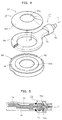
- FIG. 4 is an exploded perspective view showing the construction of the pressure detector 71 in the present embodiment.
- the pressure detector 71 comprises a pressure receiving unit 34 interposed between the bottom lid 36 of the casing 35 and the elastic member 33f to convert the pressurizing force into a detectable separate state amount, and a strain gauge unit 72 located externally of the chamber of the pressurizing device 5.
- the elastic pressurizing force is converted into the fluid pressure of a flow medium 73 by the annular pressure receiver 34.
- a diaphragm responsive member 74 is annularly disposed on the pressure receiving surface in contact with a plate spring 33f so as to follow the change in internal pressure easily.
- the strain gauge unit 72 is provided with semiconductor gauges 76a, 76b on a diaphragm 75 which deforms in response to the change in pressure to convert it into an electric amount, which is then output to a terminal 77.
- the pressure receiving unit 34 is accommodated in a recess 78, and the gauge unit 72 is disposed externally of the casing 35 via a connecting part.
- the variable speed transmission device 10 drives the input/output shafts 20, 50 which rotate at a constant speed.
- the reversible motors 53a, 53b start to drive in the direction of reducing the speed ratio, that is, while receiving a speed increasing instruction from the control device 69, the speed change power causes the shaft 18a and the shaft 48a to rotate in the direction opposite to each other as indicated by the arrow in FIG. 1.
- the screw means 15a and the screw means 25a are machined reversely to each other, when the sliding device 15 presses the disk 2a, the radius of the belt 11 starts to increase from r 10 to r 11 .
- the pressurizing device 5 having pressed at the maximum pressurizing force Pmax operates in the direction of reducing the pressurizing force of the sliding device 25 of the compression device 4.
- the sliding member 26 of the sliding device 25 moves up, the sliding member 27 reversely moves down by the amount in which winding is released, and the whole pressure pressurizing force to the elastic device 3 also is reduced to the position indicated by the dotted line.
- the falling amount of the sliding member 27 causes the pressurizing force to the pulley 1 to reduce via the lever 28 and the pressure transmission device 40 shown in FIG. 2 and at the same time, the belt 11 is pulled by the primary pulley 2, as a consequence of which the radius of the belt 11 reduces from r oo to r o1 .
- the revolution number n 1 is shifted to n 2 , the pressurizing point a 1 is shifted to a 2 , and the pressurizing force P 1 lowers to P 2 .
- the revolution number should be n 70 of 70%, as shown in the left half of FIG. 2 the compression amount of the elastic member 33 linearly reduces at a negative inclination along the characteristic line A of FIG. 6 and P 70 is assumed at point a 70 , and the pressurizing force is also transmitted from the compression device 4 and the pressure transmission device 40 to the secondary pulley 1.
- the pressurizing characteristic linearly decreases as the manipulated variable increases, and at the maximum speed rotation of the shaft 50, the minimum pressurizing force Pmin is assumed.
- the reversible motors 53a, 53b are reversibly driven to return to the original position in accordance with the above-described reverse operation.
- variable speed gear has an error factor produced within the inside and a variation factor entered from the outside, both of which comprise an obstacle against the normal transmission.
- the former includes a longitudinal elongation and a widthwise wear of the belt 11, and the latter includes a supply of a variable speed instruction and a shock load from input/output side apparatuses.
- the elastic device 3 absorbs the main cause for adverse influence automatically to decide a belt diameter in itself and to self-settle it, momentarily returns the operation to the normal transmission operation automatically again to let the belt 11 have the automatic aligning function for applying a fixed tension, and always maintains the tension and the contact radius of the belt 11 in the stable state.
- the automatic aligning function works.
- the disordered vibration by which the radius r o of the belt 11 is enlarged or reduced occurs for a moment, but this vibration is reversibly transmitted from the pressure transmission device 4 to the compression device 4.
- the vibration of the compression device 4 is transmitted from the sliding member 27 to the sliding member 26. Since the spline sliding shaft 26c at the extreme end of the sliding member 26 is engaged with the wheel 49 slidably in the axial direction, the whole compression device 4 is arranged in the vibrational floating state except that the former is engaged with the connecting element 38 of the sliding member 37.
- the elastic device 3 directly elastically absorbs the entered disordered vibration to terminate the turbulence in a short period of time.
- the internal vibration factors for the variable speed instruction or the like are totally the same.
- the value of the elastic force changes corresponding to the change in the value of the pressurizing force, its effect is positively assured in the high speed region as well as the low speed region.
- control device 69 for programable-controlling the stabilization of the accuracy of the pressurizing force of the elastic member and the belt dimension will be described with reference to FIGS. 6 to 9.
- a single variable speed instruction is branched and synchronously supplied to both the pressurizing devices 5 and 8', and the other where a variable speed instruction is fixed in the primary pulley 2, and only the secondary pulley 1 is pressed and controlled in a constant speed state. Therefore, the instruction to the secondary pulley 1 will be described here merely as an operating instruction.
- conversion where the ratio between input and output signals of the conversion characteristic B of Fig.
- the pressurizing force or revolution number selected value applied to the secondary pulley by the elastic member and the belt is always conversion-controlled as regulated signals to stabilize the accuracy and the functional effect of the elastic pressurizing force and the revolution number for a long period of time.
- the stable frictional transmission requires the compensation for substantially restoring to the original pressurizing state. Since the secondary pulley 1 requires the pressurizing change regions Pmin to Pmax determined in the storage device 66a irrespective of presence of deterioration in the elastic member, the manipulated variable E' 100 and E' o when the pressures Pmin and Pmax in the characteristic A 1 are detected by the pressure detector 71 can be read from an encoder signal R 1 of the motor 53a or an instruction E 1 from the controller 69.
- the elastic pressurizing to the secondary pulley 1 is updated by the compensation processing from the conversion characteristic B to the characteristic B 1 , and the control region between the control device 69 and the pressurizing device 5 merely changes from S o to S 1 , and the secondary pulley is maintained stably in the fixed pressurizing force as usual.
- the conversion characteristic B 1 after compensated is taken into the storage device 66b, the input operating instruction ⁇ is converted into the output operating instruction E in the characteristic B 1 and output. For example, in FIG.
- the output manipulated variable changes from E 50 to E' 50
- the output error amount ⁇ P deteriorated from a 50 to a' 50 is a deviation relative to the desired pressurizing force selected value P50 determined in the storage device 66a.
- the compression amount to the pressurizing force value of the elastic member of the pressurizing device 5 is expressed by the linear equation
- the maximum pressure information ⁇ o and Pmax, and the minimum pressure information ⁇ 100 and Pmin are obtained as 2-point information between the input manipulated variable ⁇ and the secondary pulley pressurizing force P
- the linear equation P ⁇ x ⁇ + ⁇ is stored in advance in the storage device 66a as pressurizing information necessary for the frictional transmission
- the desired pressurizing force P of the secondary pulley can be calculated as the accurate pressure value with respect to the input operating instruction ⁇ for operation, which functions as a first control means. Accordingly, pressurizing of high accuracy can be maintained with respect to arbitrary manipulated variable as long as the elastic member 33 is processed in advance in the vicinity of the optimum pressurizing characteristic required for the frictional transmission.
- the strengthening adjustment characteristic B o shown in FIG. 7 is a composite curve characteristic of the characteristic B o1 for strengthening the safety rate of transmission in the low speed region, and the characteristic B o2 for enhancing the transmission efficiency in the high speed region, and is input in advance in the storage device 66b.
- the pressure operating instruction E is supplied, as an instruction reduced in advance, to the pressurizing device 5 with the operating instruction ⁇ , and the actual pressurizing force to the secondary pulley 1 indicated by the dotted line A 01 in FIG. 6 is compelled, and the frictional transmission is further stabilized.
- the pressurizing manipulated variable E with respect to the input manipulated variable ⁇ is increased, and the secondary pulley pressurizing force is reduced.
- the reliability of the frictional transmission is strengthened, and where in the high speed region, the stable transmission continues for a long period of time, this is particularly effective for a pulley pressurizing mechanism for vehicles attaching importance to the transmission efficiency.
- the safety rate and the efficiency may be selected reversely to that mentioned above, and a plurality of characteristics may be stored and arbitrarily selected. Further, only one of them may be adjusted, and the rotation control region is also optional.
- function strengthening adjustment may be added due to the main factor other than the above rate and efficiency. For example, the variation of the elastic force during operation resulting from a rise in peripheral temperature of the elastic member may be automatically adjusted in pressure.
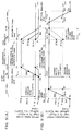
- FIG. 9 is a sequence view of a secondary control means for suppressing and substantially releasing the continuation of the high pressurizing and compression state of the elastic member 33 in a period of stoppage of the transmission device 10;
- FIG. 9A shows a release sequence when the transmission device is in transmission operation;
- FIG. 9B shows a release sequence when the transmission device is in stoppage.
- pressurizing control is accomplished by regulating signal Sa, Sr in a fixed time of a pressure applying mode T 11 and a pressure removing mode T 12 at the time of speed change of the secondary pulley 1 or before and after the pressurizing control region T 1 .
- the pressure applying mode works during the time period T 11 during transmission, and after only the elastic member is applied with pressure, the transmission device 10 enters the speed change or the pressurizing control region T 1 .
- a stop instruction is issued, only the elastic member is removed in pressure in the pressure removing mode during the off delay time T 12 with the radius of any of speed ratio positions b' 50 and b' o , after which the transmission device 10 stops.
- the storage device 66c stores the speed ratio when a stop instruction is issued by an encoder signal R 1 of the reversible motor 53a, and when the pressure applying mode T 11 is restored, the pressurizing force with the radius of the belt at the above speed ratio is supplied and restpred.
- the present example is effective when the start or stop instruction can impede the transmission by a clutch or the like between the secondary pulley and the load. If the deterioration suppression of the elastic member 33 is possible at the minimum pressure P 100 or more, it is not necessary to lower the value down to the release pressure value Ps selected specially.
- FIG. 9B shows an example in which the control device 69 independently urges and controls the pressure applying and removing modes T 11 and T 12 relative to the secondary pulley 1 even during the stoppage of the transmission device.
- the pressure applying and removing modes can be supplied separately from the start/stop instructions of the transmission device 10.
- the whole pressurizing state such as variation and deterioration of the pressurizing force can be controlled and monitored by the control operation of the pressure applying mode prior to next re-start, and in addition, slow start control for starting the transmission device 10 from the minimum speed can be applied.
- the control mode of FIG. 9A and that of FIG. 9B are suitable for general industrial machineries and vehicles or the like, respectively, and at this time, drives in both the modes may be associated with an engine key, an idling stop signal or the like.
- control device 69 executes, using a programmable controller, the error compensation and the function adjustment in the above (1) and (2), and (3) and (4), respectively, but when both of them are compounded, more excellent function can be performed. Because, at the same time when the function adjustment of the above (4) is performed, the operation of the error compensation of the above (1) and (2) can be achieved.
- the encoder manipulated variables E o , E 100 and the input manipulated variables ⁇ o , ⁇ 100 at the pressure detection values P o , P 100 of two points, for example, a point b o and a point b 100 are detected during operation of one of the pressure applying or removing modes, the constants ⁇ , ⁇ of the above linear equation after deterioration of the elastic member 33 can be calculated.
- the detection locations may be b o , b 60 or the like. Now for the attainment of the above (3) and (4), a condition detector is unnecessary.
- the conversion characteristic in FIG. 7 is momentarily updated from one-point or two-point information in the pressure applying mode, for example, in accordance with the sequence in FIG. 9 before the start of the transmission device, and all the control regions T 1 , T 2 following every start of the transmission device rely on the updated conversion characteristic.
- the updating need not necessarily be done every time of the start or stop of the transmission device, but may be done periodically after some start or stop. In any state of the contact radius between the belt and the secondary pulley, the accuracy of the pressurizing force applied to the secondary pulley by the pressurizing device 5 effectively exerts on the adequate frictional transmission in the control region as it is.
- the pressurizing force is varied, actually, in accordance with the characteristics A, and A 1 according to the manipulated variable E in FIG. 6, but in construction of the figure, the pressurizing force is lowered in accordance with the characteristics C o , C 70 with the revolution number of the secondary pulley unchanged such as n o , n 70 , thus being depicted conveniently.
- the revolution number with high accuracy for a long period of time can be assured by the technical idea substantially equal to the measure of the compensation adjustment of the pressurizing force of the elastic member 33.
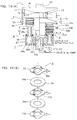
- Fig. 10 shows an apparatus according to the second embodiment of this invention, wherein Fig. 10A is a sectional view of a pressurizing apparatus assembled into the pulley 1, and Fig.10B is a perspective view of the elastic device 3 of the pressurizing device 5 disassembled.
- the entire of the pressurizing device 5 is assembled directly and revolutionally into the disk la of the driven pulley 1.
- This apparatus is different from that of Fig. 1 since the pressurizing sequence of the elastic device 3 and the compression device 4 pressing each other in series is reversed, and in other words, the elastic device 3 directly pressurizes the driven pulley 1 with reference to the revolution main member 10a.
- a fluid pressure cylinder a compression device 4 comprising a sliding device 25 composed of a plunger slider 26 and a cylinder slider 27, a pressing device 25a of a fluid medium 25c, an operating device of the conventional valve or pump etc. (not shown) connected mechanically and individually to each two pressurizing devices.
- the compression device 4 may be a cylinder construction in which the well-known disk la serves also as the slider 26 of the sliding device 25.
- FIG. 10B shows a further embodiment of the wavy plate-like elastic member, which is a special elastic member 33 having an inclined bent part which is horizontal in a radial direction and is wavy in a thickness direction, that is, in a circumferential (tangential) direction.
- the elastic member 33 has a partitioning plate 34 in which a wave washer having three crests and troughs is large-scaled to maintain series pressurizing instead of parallel, and three elastic members 33a to 33c, and partitioning plates 34a to 34b are incorporated therein integrally. If the elastic members 33 are made the same in thickness, the linear characteristic is obtained, and control processing is simplified.
- the displacement amount L o of the compression device 4 shown has been the sum of two displacement amounts L o1 and L o2
- the scope that can be readily created by those skilled in the art from claims in the present specification falls under the right of the present invention.
- Parts in which the elastic force of the elastic member plays on the frictional transmission surface include (1) the self settling function of the pressurizing force on the contact surface; (2) the automatic aligning function between the pulley and the belt transmission; and (3) in case of the variable speed transmission device, the security of high speed responsiveness assured by the stable automatic restoring action thereby.
- the apparatus according to the present invention has the effect that one or both of the restoring compensation of an error in pressurizing force generated in the elastic member and the strengthening adjustment for maintaining the added function of the desired pressurizing force are subjected to programmable control according to the operating instruction to always achieve the above three functions in the whole control region over a long period of time.
- variation of the revolution number or speed ratio caused by the elongation of the circumferential length of the belt and the deformation and deterioration of the thickness can be also maintained stably over a long period of time by the pressurizing compensation or the pressurizing adjustment of the non-elastic pressurizing force to the pulley.
- a variable torque operating mode responsive to a revolution number of a variable speed input can be achieved in a constant speed-ratio state, and oppositely when supplied only to a pulley added a non-elastic force, a constant torque of a variable speed transmission is fulfilled.
- the present invention has the advantage so that a variety of control systems for a variable speed transmission can be selected at a operator's disposal only by manipulating collectively in the side of the control device.
Landscapes
- Engineering & Computer Science (AREA)
- General Engineering & Computer Science (AREA)
- Mechanical Engineering (AREA)
- Transmissions By Endless Flexible Members (AREA)
- Control Of Transmission Device (AREA)
- Devices For Conveying Motion By Means Of Endless Flexible Members (AREA)
Applications Claiming Priority (2)
| Application Number | Priority Date | Filing Date | Title |
|---|---|---|---|
| JP35966999A JP4472077B2 (ja) | 1999-11-13 | 1999-11-13 | 無段可変伝動機 |
| JP35966999 | 1999-11-13 |
Publications (3)
| Publication Number | Publication Date |
|---|---|
| EP1099885A2 true EP1099885A2 (de) | 2001-05-16 |
| EP1099885A3 EP1099885A3 (de) | 2003-12-03 |
| EP1099885B1 EP1099885B1 (de) | 2006-06-14 |
Family
ID=18465691
Family Applications (1)
| Application Number | Title | Priority Date | Filing Date |
|---|---|---|---|
| EP00124597A Expired - Lifetime EP1099885B1 (de) | 1999-11-13 | 2000-11-10 | Stufenloses Getriebe und Steuerungssystem für die elastische Klemmkraft |
Country Status (4)
| Country | Link |
|---|---|
| US (1) | US6494798B1 (de) |
| EP (1) | EP1099885B1 (de) |
| JP (1) | JP4472077B2 (de) |
| DE (1) | DE60028695T2 (de) |
Cited By (5)
| Publication number | Priority date | Publication date | Assignee | Title |
|---|---|---|---|---|
| WO2003048612A3 (en) * | 2001-12-04 | 2003-09-04 | Yamaha Motor Co Ltd | Continuously variable transmission and method of controlling it |
| EP1880127A4 (de) * | 2005-05-02 | 2010-09-29 | Purdue Research Foundation | Vorrichtungen zur elektrischen unterstützung und betätigung kontinuierlich variabler getriebe |
| US7980973B1 (en) | 2006-05-01 | 2011-07-19 | Purdue Research Foundation | Coaxial electrical actuator for continuously variable transmissions |
| US7980972B1 (en) | 2006-05-01 | 2011-07-19 | Purdue Research Foundation | Roller variator for actuating continuously variable transmissions |
| GB2529504A (en) * | 2014-05-12 | 2016-02-24 | Manousos Pattakos | CVT V-belt over-clamping |
Families Citing this family (18)
| Publication number | Priority date | Publication date | Assignee | Title |
|---|---|---|---|---|
| JP4729833B2 (ja) * | 2001-05-10 | 2011-07-20 | 東京自動機工株式会社 | 伝動機のプーリ加圧制御装置 |
| DE10226861B4 (de) * | 2002-06-15 | 2012-11-08 | Zf Friedrichshafen Ag | Stufenlos regelbares Umschlingungsgetriebe |
| US6966882B2 (en) | 2002-11-25 | 2005-11-22 | Tibion Corporation | Active muscle assistance device and method |
| US7641599B2 (en) * | 2004-04-27 | 2010-01-05 | Mitsubishi Electric Engineering Company, Limited | Exercise therapy device |
| JP4627425B2 (ja) * | 2004-09-29 | 2011-02-09 | 本田技研工業株式会社 | 無段変速機の変速制御装置 |
| US7648436B2 (en) * | 2005-12-30 | 2010-01-19 | Tibion Corporation | Rotary actuator |
| US7811189B2 (en) | 2005-12-30 | 2010-10-12 | Tibion Corporation | Deflector assembly |
| US8353854B2 (en) | 2007-02-14 | 2013-01-15 | Tibion Corporation | Method and devices for moving a body joint |
| WO2009031669A1 (ja) * | 2007-09-05 | 2009-03-12 | Nsk Ltd. | 無段変速機、アクチュエータ及び中間端子 |
| WO2009099671A2 (en) | 2008-02-08 | 2009-08-13 | Tibion Corporation | Multi-fit orthotic and mobility assistance apparatus |
| US20090306548A1 (en) | 2008-06-05 | 2009-12-10 | Bhugra Kern S | Therapeutic method and device for rehabilitation |
| US8274244B2 (en) | 2008-08-14 | 2012-09-25 | Tibion Corporation | Actuator system and method for extending a joint |
| US8058823B2 (en) | 2008-08-14 | 2011-11-15 | Tibion Corporation | Actuator system with a multi-motor assembly for extending and flexing a joint |
| US8639455B2 (en) | 2009-02-09 | 2014-01-28 | Alterg, Inc. | Foot pad device and method of obtaining weight data |
| EP2916039A4 (de) * | 2013-02-14 | 2016-04-13 | Aisin Aw Co | Triebkraftübertragungsvorrichtung |
| WO2014151584A1 (en) | 2013-03-15 | 2014-09-25 | Alterg, Inc. | Orthotic device drive system and method |
| JP6208589B2 (ja) * | 2014-02-04 | 2017-10-04 | 日立オートモティブシステムズ株式会社 | 可変圧縮比機構のアクチュエータとリンク機構のアクチュエータ |
| WO2022165160A1 (en) * | 2021-01-29 | 2022-08-04 | Polaris Industries Inc. | Electronically-controlled continuously variable transmission for a utility vehicle |
Citations (3)
| Publication number | Priority date | Publication date | Assignee | Title |
|---|---|---|---|---|
| US5180339A (en) | 1991-06-26 | 1993-01-19 | Borg-Warner Automotive, Inc. | Double acting secondary sheave servo for a continuously variable transmission |
| JPH09217819A (ja) | 1995-11-28 | 1997-08-19 | Van Doornes Transmissie Bv | プーリ |
| JPH10321246A (ja) | 1997-05-16 | 1998-12-04 | Honda Motor Co Ltd | 燃料電池システム |
Family Cites Families (9)
| Publication number | Priority date | Publication date | Assignee | Title |
|---|---|---|---|---|
| US4541821A (en) * | 1982-11-27 | 1985-09-17 | Aisin-Warner Limited | V-belt type stepless transmission |
| US4504247A (en) * | 1983-06-08 | 1985-03-12 | General Motors Corporation | Control mechanism for a variable ratio drive system |
| US4631043A (en) * | 1984-05-03 | 1986-12-23 | Toyota Jidosha Kabushiki Kaisha | Hydraulic control apparatus for a continuously variable transmission |
| US4619629A (en) * | 1984-05-03 | 1986-10-28 | Toyota Jidosha Kabushiki Kaisha | Hydraulic pressure control apparatus for a continuously variable transmission |
| WO1988004002A1 (fr) * | 1986-11-26 | 1988-06-02 | Tokyo Jido Kiko Kabushiki Kaisha | Transmission par courroie |
| JP2548224B2 (ja) * | 1987-08-28 | 1996-10-30 | アイシン・エィ・ダブリュ株式会社 | ベルト式無段変速装置 |
| US6120400A (en) * | 1998-01-26 | 2000-09-19 | Tokyo Automatic Machinery Co, Ltd | Transmission wheel pressurizing apparatus for transmitting constant power in a variable speed transmission |
| JP3498901B2 (ja) * | 1998-12-25 | 2004-02-23 | 日産自動車株式会社 | ベルト式無段変速機の制御装置 |
| JP3498900B2 (ja) * | 1998-12-25 | 2004-02-23 | 日産自動車株式会社 | ベルト式無段変速機の制御装置 |
-
1999
- 1999-11-13 JP JP35966999A patent/JP4472077B2/ja not_active Expired - Lifetime
-
2000
- 2000-11-09 US US09/708,461 patent/US6494798B1/en not_active Expired - Lifetime
- 2000-11-10 DE DE60028695T patent/DE60028695T2/de not_active Expired - Lifetime
- 2000-11-10 EP EP00124597A patent/EP1099885B1/de not_active Expired - Lifetime
Patent Citations (3)
| Publication number | Priority date | Publication date | Assignee | Title |
|---|---|---|---|---|
| US5180339A (en) | 1991-06-26 | 1993-01-19 | Borg-Warner Automotive, Inc. | Double acting secondary sheave servo for a continuously variable transmission |
| JPH09217819A (ja) | 1995-11-28 | 1997-08-19 | Van Doornes Transmissie Bv | プーリ |
| JPH10321246A (ja) | 1997-05-16 | 1998-12-04 | Honda Motor Co Ltd | 燃料電池システム |
Non-Patent Citations (1)
| Title |
|---|
| "1998 to 99 SERVO SYSTEM GENERAL CATALOGUE", SANYO DENKI CO., LTD |
Cited By (5)
| Publication number | Priority date | Publication date | Assignee | Title |
|---|---|---|---|---|
| WO2003048612A3 (en) * | 2001-12-04 | 2003-09-04 | Yamaha Motor Co Ltd | Continuously variable transmission and method of controlling it |
| EP1880127A4 (de) * | 2005-05-02 | 2010-09-29 | Purdue Research Foundation | Vorrichtungen zur elektrischen unterstützung und betätigung kontinuierlich variabler getriebe |
| US7980973B1 (en) | 2006-05-01 | 2011-07-19 | Purdue Research Foundation | Coaxial electrical actuator for continuously variable transmissions |
| US7980972B1 (en) | 2006-05-01 | 2011-07-19 | Purdue Research Foundation | Roller variator for actuating continuously variable transmissions |
| GB2529504A (en) * | 2014-05-12 | 2016-02-24 | Manousos Pattakos | CVT V-belt over-clamping |
Also Published As
| Publication number | Publication date |
|---|---|
| DE60028695D1 (de) | 2006-07-27 |
| EP1099885B1 (de) | 2006-06-14 |
| US6494798B1 (en) | 2002-12-17 |
| JP4472077B2 (ja) | 2010-06-02 |
| DE60028695T2 (de) | 2007-05-24 |
| EP1099885A3 (de) | 2003-12-03 |
| JP2001141000A (ja) | 2001-05-22 |
Similar Documents
| Publication | Publication Date | Title |
|---|---|---|
| EP1099885B1 (de) | Stufenloses Getriebe und Steuerungssystem für die elastische Klemmkraft | |
| US6764421B2 (en) | Pulley pressure control system for transmission | |
| US4533340A (en) | Hydraulic control system for continuously variable V-belt transmission | |
| US6398680B1 (en) | Continuously variable transmission | |
| JP4164057B2 (ja) | ベルト式無段変速機 | |
| JP4380847B2 (ja) | 伝動機の伝達体加圧制御装置 | |
| EP0931960B1 (de) | Druckvorrichtung für Riemenscheibe eines stufenlosen Getriebes | |
| JP4410865B2 (ja) | 伝達車加圧装置用圧縮装置 | |
| JP4590343B2 (ja) | 車両用ベルト式無段変速機の油圧制御装置 | |
| EP1906059B1 (de) | Stufenlos verstellbares Getriebe | |
| JP5312414B2 (ja) | 可変伝動機 | |
| JP5095787B2 (ja) | 可変伝動機 | |
| JP4417457B2 (ja) | 無段変速機および同機用変速制御装置 | |
| JP6065337B2 (ja) | ベルト可変伝動機 | |
| JP4221099B2 (ja) | 変速制御装置 | |
| JP5271374B2 (ja) | 可変伝動機 | |
| JP5155956B2 (ja) | 伝達車加圧装置 | |
| JP2013036619A (ja) | 可変伝動機 | |
| JP2010281453A5 (de) |
Legal Events
| Date | Code | Title | Description |
|---|---|---|---|
| PUAI | Public reference made under article 153(3) epc to a published international application that has entered the european phase |
Free format text: ORIGINAL CODE: 0009012 |
|
| AK | Designated contracting states |
Kind code of ref document: A2 Designated state(s): AT BE CH CY DE DK ES FI FR GB GR IE IT LI LU MC NL PT SE TR |
|
| AX | Request for extension of the european patent |
Free format text: AL;LT;LV;MK;RO;SI |
|
| PUAL | Search report despatched |
Free format text: ORIGINAL CODE: 0009013 |
|
| AK | Designated contracting states |
Kind code of ref document: A3 Designated state(s): AT BE CH CY DE DK ES FI FR GB GR IE IT LI LU MC NL PT SE TR |
|
| AX | Request for extension of the european patent |
Extension state: AL LT LV MK RO SI |
|
| 17P | Request for examination filed |
Effective date: 20040603 |
|
| AKX | Designation fees paid |
Designated state(s): DE FR GB IT |
|
| 17Q | First examination report despatched |
Effective date: 20040721 |
|
| GRAP | Despatch of communication of intention to grant a patent |
Free format text: ORIGINAL CODE: EPIDOSNIGR1 |
|
| GRAS | Grant fee paid |
Free format text: ORIGINAL CODE: EPIDOSNIGR3 |
|
| GRAA | (expected) grant |
Free format text: ORIGINAL CODE: 0009210 |
|
| AK | Designated contracting states |
Kind code of ref document: B1 Designated state(s): DE FR GB IT |
|
| PG25 | Lapsed in a contracting state [announced via postgrant information from national office to epo] |
Ref country code: IT Free format text: LAPSE BECAUSE OF FAILURE TO SUBMIT A TRANSLATION OF THE DESCRIPTION OR TO PAY THE FEE WITHIN THE PRESCRIBED TIME-LIMIT;WARNING: LAPSES OF ITALIAN PATENTS WITH EFFECTIVE DATE BEFORE 2007 MAY HAVE OCCURRED AT ANY TIME BEFORE 2007. THE CORRECT EFFECTIVE DATE MAY BE DIFFERENT FROM THE ONE RECORDED. Effective date: 20060614 |
|
| RAP1 | Party data changed (applicant data changed or rights of an application transferred) |
Owner name: TOKYO AUTOMATIC MACHINERY CO., LTD. |
|
| REG | Reference to a national code |
Ref country code: GB Ref legal event code: FG4D |
|
| REF | Corresponds to: |
Ref document number: 60028695 Country of ref document: DE Date of ref document: 20060727 Kind code of ref document: P |
|
| PLBE | No opposition filed within time limit |
Free format text: ORIGINAL CODE: 0009261 |
|
| STAA | Information on the status of an ep patent application or granted ep patent |
Free format text: STATUS: NO OPPOSITION FILED WITHIN TIME LIMIT |
|
| EN | Fr: translation not filed | ||
| 26N | No opposition filed |
Effective date: 20070315 |
|
| PG25 | Lapsed in a contracting state [announced via postgrant information from national office to epo] |
Ref country code: FR Free format text: LAPSE BECAUSE OF FAILURE TO SUBMIT A TRANSLATION OF THE DESCRIPTION OR TO PAY THE FEE WITHIN THE PRESCRIBED TIME-LIMIT Effective date: 20070309 |
|
| PG25 | Lapsed in a contracting state [announced via postgrant information from national office to epo] |
Ref country code: FR Free format text: LAPSE BECAUSE OF FAILURE TO SUBMIT A TRANSLATION OF THE DESCRIPTION OR TO PAY THE FEE WITHIN THE PRESCRIBED TIME-LIMIT Effective date: 20060614 |
|
| PGFP | Annual fee paid to national office [announced via postgrant information from national office to epo] |
Ref country code: DE Payment date: 20191121 Year of fee payment: 20 |
|
| PGFP | Annual fee paid to national office [announced via postgrant information from national office to epo] |
Ref country code: GB Payment date: 20191120 Year of fee payment: 20 |
|
| REG | Reference to a national code |
Ref country code: DE Ref legal event code: R071 Ref document number: 60028695 Country of ref document: DE |
|
| REG | Reference to a national code |
Ref country code: GB Ref legal event code: PE20 Expiry date: 20201109 |
|
| PG25 | Lapsed in a contracting state [announced via postgrant information from national office to epo] |
Ref country code: GB Free format text: LAPSE BECAUSE OF EXPIRATION OF PROTECTION Effective date: 20201109 |