EP1099601B1 - Kraftfahrzeugleuchte - Google Patents
Kraftfahrzeugleuchte Download PDFInfo
- Publication number
- EP1099601B1 EP1099601B1 EP00123767A EP00123767A EP1099601B1 EP 1099601 B1 EP1099601 B1 EP 1099601B1 EP 00123767 A EP00123767 A EP 00123767A EP 00123767 A EP00123767 A EP 00123767A EP 1099601 B1 EP1099601 B1 EP 1099601B1
- Authority
- EP
- European Patent Office
- Prior art keywords
- light
- carrier film
- emitting diodes
- carrier
- emitting diode
- Prior art date
- Legal status (The legal status is an assumption and is not a legal conclusion. Google has not performed a legal analysis and makes no representation as to the accuracy of the status listed.)
- Expired - Lifetime
Links
Images


Classifications
-
- H—ELECTRICITY
- H01—ELECTRIC ELEMENTS
- H01L—SEMICONDUCTOR DEVICES NOT COVERED BY CLASS H10
- H01L25/00—Assemblies consisting of a plurality of individual semiconductor or other solid state devices ; Multistep manufacturing processes thereof
- H01L25/03—Assemblies consisting of a plurality of individual semiconductor or other solid state devices ; Multistep manufacturing processes thereof all the devices being of a type provided for in the same subgroup of groups H01L27/00 - H01L33/00, or in a single subclass of H10K, H10N, e.g. assemblies of rectifier diodes
- H01L25/10—Assemblies consisting of a plurality of individual semiconductor or other solid state devices ; Multistep manufacturing processes thereof all the devices being of a type provided for in the same subgroup of groups H01L27/00 - H01L33/00, or in a single subclass of H10K, H10N, e.g. assemblies of rectifier diodes the devices having separate containers
- H01L25/13—Assemblies consisting of a plurality of individual semiconductor or other solid state devices ; Multistep manufacturing processes thereof all the devices being of a type provided for in the same subgroup of groups H01L27/00 - H01L33/00, or in a single subclass of H10K, H10N, e.g. assemblies of rectifier diodes the devices having separate containers the devices being of a type provided for in group H01L33/00
-
- B—PERFORMING OPERATIONS; TRANSPORTING
- B60—VEHICLES IN GENERAL
- B60Q—ARRANGEMENT OF SIGNALLING OR LIGHTING DEVICES, THE MOUNTING OR SUPPORTING THEREOF OR CIRCUITS THEREFOR, FOR VEHICLES IN GENERAL
- B60Q1/00—Arrangement of optical signalling or lighting devices, the mounting or supporting thereof or circuits therefor
- B60Q1/26—Arrangement of optical signalling or lighting devices, the mounting or supporting thereof or circuits therefor the devices being primarily intended to indicate the vehicle, or parts thereof, or to give signals, to other traffic
- B60Q1/2696—Mounting of devices using LEDs
-
- F—MECHANICAL ENGINEERING; LIGHTING; HEATING; WEAPONS; BLASTING
- F21—LIGHTING
- F21S—NON-PORTABLE LIGHTING DEVICES; SYSTEMS THEREOF; VEHICLE LIGHTING DEVICES SPECIALLY ADAPTED FOR VEHICLE EXTERIORS
- F21S43/00—Signalling devices specially adapted for vehicle exteriors, e.g. brake lamps, direction indicator lights or reversing lights
- F21S43/10—Signalling devices specially adapted for vehicle exteriors, e.g. brake lamps, direction indicator lights or reversing lights characterised by the light source
- F21S43/13—Signalling devices specially adapted for vehicle exteriors, e.g. brake lamps, direction indicator lights or reversing lights characterised by the light source characterised by the type of light source
- F21S43/14—Light emitting diodes [LED]
-
- F—MECHANICAL ENGINEERING; LIGHTING; HEATING; WEAPONS; BLASTING
- F21—LIGHTING
- F21V—FUNCTIONAL FEATURES OR DETAILS OF LIGHTING DEVICES OR SYSTEMS THEREOF; STRUCTURAL COMBINATIONS OF LIGHTING DEVICES WITH OTHER ARTICLES, NOT OTHERWISE PROVIDED FOR
- F21V19/00—Fastening of light sources or lamp holders
- F21V19/001—Fastening of light sources or lamp holders the light sources being semiconductors devices, e.g. LEDs
- F21V19/0015—Fastening arrangements intended to retain light sources
- F21V19/002—Fastening arrangements intended to retain light sources the fastening means engaging the encapsulation or the packaging of the semiconductor device
-
- F—MECHANICAL ENGINEERING; LIGHTING; HEATING; WEAPONS; BLASTING
- F21—LIGHTING
- F21V—FUNCTIONAL FEATURES OR DETAILS OF LIGHTING DEVICES OR SYSTEMS THEREOF; STRUCTURAL COMBINATIONS OF LIGHTING DEVICES WITH OTHER ARTICLES, NOT OTHERWISE PROVIDED FOR
- F21V19/00—Fastening of light sources or lamp holders
- F21V19/001—Fastening of light sources or lamp holders the light sources being semiconductors devices, e.g. LEDs
- F21V19/003—Fastening of light source holders, e.g. of circuit boards or substrates holding light sources
- F21V19/004—Fastening of light source holders, e.g. of circuit boards or substrates holding light sources by deformation of parts or snap action mountings, e.g. using clips
-
- H—ELECTRICITY
- H01—ELECTRIC ELEMENTS
- H01L—SEMICONDUCTOR DEVICES NOT COVERED BY CLASS H10
- H01L2924/00—Indexing scheme for arrangements or methods for connecting or disconnecting semiconductor or solid-state bodies as covered by H01L24/00
- H01L2924/0001—Technical content checked by a classifier
- H01L2924/0002—Not covered by any one of groups H01L24/00, H01L24/00 and H01L2224/00
Definitions
- the invention relates to a motor vehicle light having a luminaire housing, in which a plurality of light-emitting diodes are arranged on at least one electrical conductor tracks connected to terminal contacts of the light-emitting conductors, wherein at least one of the light-emitting diodes positively engages in a receptacle provided on the lamp housing.
- a motor vehicle lamp of the aforementioned type which has a printed circuit board designed as a printed circuit board, on which a plurality of light-emitting diodes are arranged.
- the conductor carrier has a plurality of approximately parallel to each other arranged strip-shaped regions which are separated by slots. At one of its two narrow-side ends, the strip-shaped regions are connected to each other by a transverse thereto printed circuit board area. On each of these strip-shaped areas each have a plurality of light-emitting diodes are arranged.
- the light-emitting diodes are first mounted on a flat, continuous circuit board and then be used to form the strip-shaped areas Slots introduced into the circuit board. Subsequently, the strip-shaped areas are permanently deformed, in which they are pivoted with their free ends out of the plane of the circuit board and adapted in shape to the deviating from the plane shape of the receiving area of the lamp housing, in which the circuit board is to be used.
- the luminaire housing has in each case a receptacle for each light-emitting diode into which the individual light-emitting diodes are inserted in the position of use.
- the recording encloses the light-emitting diodes form fit.
- the previously known motor vehicle lamp allows a simple assembly of the conductor carrier in a plane, but has the disadvantage that the introduction of the strip-shaped areas in the conductor carrier and the subsequent deformation of these areas is still relatively expensive. It is also unfavorable that the slots located between the strip-shaped regions obstruct the conductor track guidance of the interconnects on the interconnect carrier. Since the direction in which the individual light-emitting diodes are aligned, is determined by the curvature of the permanently deformed strip-shaped regions of the conductor carrier, the insertion of the light emitting diodes is difficult in the assembly of the respective light housings associated with the assembly of the motor vehicle light.
- a motor vehicle lamp which has a plate-shaped carrier part consisting of metal, on which a plurality of light-emitting diodes are arranged.
- the carrier part has a plurality of electrically mutually insulated carrier plate areas, which are interconnected by slots which are bridged by the light-emitting diodes. These plate areas form the power supply lines for the LEDs.
- the individual carrier plate areas are partially formed as a mesh fabric, which can be permanently deformed by bending deformation in order to adapt the light-emitting diode in its position, for example, to the shape of a lamp housing.
- Unfavorable is that in the bending deformation of the support plate areas bending forces can be transmitted to the light emitting diodes. Unfavorable is also that the serving as power supply lines for the LEDs support plate areas allow only a common power supply and control of the light-emitting diodes.
- a motor vehicle lamp in which a prismatic body can be fixed by means of a flange. On one side, the prismatic body has openings for inserting LEDs held by a flexible substrate.
- the conductor carrier is at least partially formed as a flexible carrier film and that at least one light emitting diode is arranged at both of the opposite flat sides of the carrier film.
- the light-emitting diodes can thereby be mounted on it in flat position conductor track carrier and then the conductor track carrier is brought from the flat position to the position required for the position of use.
- the carrier foil can also be inserted into the receptacles of the luminaire housing during the insertion of the light-emitting diodes bent and placed in a position favorable for the insertion of the LEDs.
- the light-emitting diodes can thereby be easily brought into the position required for the desired light distribution, so that the light distribution can be achieved without the use of further optical components.
- the carrier film may consist of an elastically or plastically bend-deformable and / or stretchable material, in particular of plastic.
- luminaire housing with differently arranged and / or aligned light-emitting diode recordings it is even possible for luminaire housing with differently arranged and / or aligned light-emitting diode recordings to provide the same strip conductor carrier, and then to deform the strip conductor carrier accordingly upon insertion into the respective lamp housing.
- development, manufacturing and storage costs for the conductor carrier of the different motor vehicle lights can be saved.
- the flexible carrier film also allows a simple conductor track guidance of the conductor tracks required for the power supply of the light-emitting diode (s).
- the conductor tracks can extend transversely to one another and / or be arranged in different planes of the carrier film.
- the light-emitting diode (s) and / or the carrier foil may also be cast into the part of the luminaire housing having the receptacle (s) for the light-emitting diode (s) or encapsulated with it. In this case, first the light-emitting diodes are mounted on the carrier film and then the light emitting diode (s) and carrier film existing arrangement is inserted into a casting or injection mold and positioned in the desired position.
- the light-emitting diodes in the form are coated with a flowable, solidifying by hardening and / or solidification material, preferably in the hot-molded process.
- this material preferably delimits the LEDs laterally, while the light exit surface of the LEDs remains free of the material.
- the light-emitting diodes can also be encased in their light exit surface of the material of the recording when it is translucent.
- the motor vehicle lamp according to the invention enables a uniform light output in different directions.
- the receptacle is designed as a plug-in receptacle into which the light-emitting diode can be inserted from a pre-assembly position in the plug-in direction and is preferably positionable against a stop provided on the lamp housing in the assembly position.
- the receptacle may have a slightly smaller inside diameter than the diameter or the outside dimension of the light-emitting diode.
- the receptacle preferably consists of a resilient material against the restoring force of their material.
- the receptacle may be tapered with a cross-section tapering in the insertion direction of the light-emitting diode.
- at least one in the position of use of the LED-facing projection may be arranged, which preferably has at least one pointed and / or a sharp edge, which penetrates slightly when inserting the light-emitting diode into the housing of the light-emitting diode and fixes them in the receptacle.
- the carrier film has a central region in which preferably a plurality of LEDs are arranged, that on both sides of the central region in each case at least one particular strap-shaped continuation of the carrier film is provided that arranged on this continuation in each case at least one light emitting diode is, and that the sequels are preferably pivoted to illuminate lateral areas in the use position of the flat position.
- This results in a simply mountable motor vehicle light which emits light even in an oblique to the emission region of the light-emitting diode (s) of the central region. Due to the oblique light emission of the lateral light-emitting diode (s), a uniform illumination of the vehicle interior can be achieved, for example, in the case of a motor vehicle light designed as an interior light for illuminating a vehicle interior.
- the luminaire housing has a receiving area which is approximately U-shaped in cross-section, in that the carrier foil is approximately U-shaped in the mounting position, at least one receptacle designed as a through-perforation being provided on the opposite side walls of this receiving area, into which one on the carrier foil arranged light emitting diode is inserted positively.
- the carrier film is then used on the side walls of the receiving region, which are designed, for example, as U-Schwenkel, over the receptacles located there Fixed LEDs and may optionally be additionally supported in the central region located between these light emitting diodes on the U-crosspiece of the recording.
- the carrier film may have at least two partial regions, in each of which at least one light-emitting diode is arranged, these partial regions being connected to one another by a meander-shaped, slotted region of the carrier film.
- the two subareas of the carrier film can then be arranged in the plane of the carrier film at different distances from each other and in particular pulled apart or moved toward each other. The LEDs are then even better used in the mounting of the lamp housing in the mounting of the lamp housing.
- the carrier film can be better adapted to luminaire housing with different dimensions and / or differently arranged LED recordings.
- At least one further electronic component is arranged on the carrier foil, wherein this component is in particular part of control electronics for driving the light-emitting diodes.
- the additional components can then be mounted together with the LEDs on the carrier film.
- the control electronics can in particular have a device for controlling the brightness of at least one light-emitting diode and / or a device for temperature-dependent adjustment or limitation of the light-emitting diode current.
- a generally designated 1 motor vehicle light comprises a lamp housing 2, in which a plurality of light-emitting diodes 3a, 3b are arranged on a formed as a flexible carrier film conductor carriers 4.
- the carrier film has, in the drawing, not shown traces for powering the LEDs 3a, 3b, which are connected to terminal contacts of the LEDs 3a, 3b. 1, 4 and 5 it can be seen that in each case a plurality of the light-emitting diodes 3 a form-fit in receptacles 5 provided on the luminaire housing 2 intervention. About these light-emitting diodes 3 a of the conductor track carrier 4 is attached to the lamp housing 2.
- the receptacles 5 are each formed as plug-in receptacles, in which the light-emitting diodes 3a can be inserted from a pre-assembly position in the insertion direction marked by the arrow Pf1.
- the light-emitting diodes 3 a have, at their housing end facing the conductor carrier 4, in each case an annular collar which, in the assembled position of the light-emitting diodes 3 a, bears against a stop provided on the receptacle 5 and faces the annular collar.
- the light-emitting diodes 3 a, 3 d are mounted on the strip conductor carrier 4 (FIG. 2) in flat position and then the conductor carrier 4 with the light-emitting diodes 3 a, 3 b inserted into the receiving region 6 of the light housing 2 is inserted the light-emitting diodes 3 a are inserted into the receptacles 5.
- the motor vehicle light 1 is thus easy and inexpensive to install.
- the carrier foil has a central region in which a plurality of light-emitting diodes 3 b formed in SMT technology are arranged.
- these LEDs 3b are each indicated schematically by crosses.
- a lug-shaped continuation 7 of the carrier film is provided, which carries a conventional light-emitting diode 3 a adjacent to its free end facing away from the central area.
- these tab-like continuations are arranged diametrically opposite with their extension directions approximately radially to the center of the central region of the carrier film.
- those located on the lug-shaped continuations 7 are located Light-emitting diodes 3a are each arranged on the rear side of the carrier film facing away from the light-emitting diodes 3b of the central region.
- Fig. 1 shows the carrier film in the assembled position. It can clearly be seen that the light-emitting diodes 3 a of the lug-shaped continuations 7 are inserted into receptacles 5 arranged on the side walls 8 of the receiving area 6 of the luminaire housing 2 which is of U-shaped cross-section. This receptacle 5 are formed by perforations, which pass through the side wall 8 of the U-shaped receiving portion 6. In this case, the light-emitting diodes 3 a are arranged with their light exit surface on the end of the receptacle 5 facing away from the carrier film, so that they can emit light in a lateral region on the rear side of the side wall remote from the conductor carrier 4. In Fig.
- the central region of the carrier film is arranged approximately parallel to the bottom of the U-shaped receiving portion 6 and is supported on the back against this or rests against this.
- the light-emitting diodes 3b Arranged on the front side of the central region are the light-emitting diodes 3b, which are aligned with their emission direction approximately at right angles to the plane of the bottom of the U-shaped receiving region 6.
- the receptacles 5 are each arranged obliquely to the plane of the wall of the lamp housing 2. It can clearly be seen that the receptacles 5 are each formed as through holes, and that these through holes are arranged with their axes parallel to each other.
- the conductor carrier 4 on the one hand flexible and on the other hand also largely rigid areas.
- the central circuit board area is rigid in each case, while the laterally arranged sequels are flexible.
- the central rigid region of the conductor carrier 4 has a greater thickness than the flexible continuations.
- any other arrangements of interconnected rigid and flexible conductor carriers are conceivable, for example an arrangement in which the flexible region is provided centrally and the rigid regions at the edges of the conductor carrier 4.
- the light-emitting diodes 3 b are arranged on the rear side of the continuation 7 arranged on both sides of the central conductor carrier area and on the rear side of the conductor carrier 4 in the other continuation 7.
- a plurality of tab-like continuations can be provided on one side of the central circuit board area, which are arranged transversely to their direction of extension next to each other. In assembly position, such multiple extensions 7 may be inclined at different angles from the plane of the central region, whereby a desired light distribution can be achieved without the use of multiple optical components, such as lenses or deflecting mirrors.
- the carrier film has two partial regions 9, which are connected to one another by a meander-shaped, slotted region 10 of the carrier film.
- a group with a plurality of light-emitting diodes 3 a is arranged in each case.
- the slotted region 10 By means of the slotted region 10, the two subregions 9 of the carrier film in the plane of the carrier film to each other transverse to the direction of extension of the slots from a rest position moved to and away from each other.
- the portions 10 can be moved in the direction of extension of the slots against each other.
- the meandering region 10 also makes it possible to pivot the subregions 9 of the carrier film with their planes against each other.
- FIG. 6 also shows that, in addition to the light emitting diodes 3a on the carrier foil, an electronic control unit 11, shown only schematically in the drawing, is arranged with a temperature sensor 12.
- the control electronics 11 has a current control circuit for the LEDs 3a, which is connected via interconnects on the one hand to the temperature sensor 12 and on the other hand to the electrical terminals of the LEDs 3a.
- the current control circuit By means of the current control circuit, the operating current of the light-emitting diodes 3a is controlled as a function of the ambient temperature. Above a predetermined limit temperature, the operating current of the light emitting diode 3a is reduced with increasing temperature. The reduction of the operating current can take place in stages or continuously. Below the limit temperature, the LEDs are energized with a constant operating current.
- Fig. 1 it can still be seen that the luminaire housing 2 lichtabstrahl spot an optically transparent lens 13 has.
- the lens 13 may optionally be integrated optical scattering elements.
Landscapes
- Engineering & Computer Science (AREA)
- Microelectronics & Electronic Packaging (AREA)
- General Engineering & Computer Science (AREA)
- Power Engineering (AREA)
- Physics & Mathematics (AREA)
- General Physics & Mathematics (AREA)
- Condensed Matter Physics & Semiconductors (AREA)
- Mechanical Engineering (AREA)
- Computer Hardware Design (AREA)
- Optics & Photonics (AREA)
- Led Device Packages (AREA)
- Non-Portable Lighting Devices Or Systems Thereof (AREA)
- Arrangements Of Lighting Devices For Vehicle Interiors, Mounting And Supporting Thereof, Circuits Therefore (AREA)
- Lighting Device Outwards From Vehicle And Optical Signal (AREA)
Description
- Die Erfindung betrifft eine Kraftfahrzeugleuchte mit einem Leuchtengehäuse, in dem mehrere Leuchtdioden auf zumindest einem mit Anschlusskontakten der Leuchtdioden verbundene elektrische Leiterbahnen aufweisenden Leiterbahnträger angeordnet sind, wobei wenigstens eine der Leuchtdioden formschlüssig in eine an dem Leuchtengehäuse vorgesehenen Aufnahme eingreift.
- Aus
EP 0 531 185 B1 ist bereits eine Kraftfahrzeugleuchte der eingangs genannten Art bekannt, die einen als Leiterplatte ausgebildeten Leiterbahnträger aufweist, auf dem mehrere Leuchtdioden angeordnet sind. Der Leiterbahnträger weist mehrere, etwa parallel zueinander angeordnete streifenförmige Bereiche auf, die durch Schlitze voneinander getrennt sind. An einem ihrer beiden schmalseitigen Enden sind die streifenförmigen Bereiche durch einen quer dazu verlaufenden Leiterplattenbereich miteinander verbunden. Auf jedem dieser streifenförmigen Bereiche sind jeweils mehrere Leuchtdioden angeordnet. - Bei der Herstellung des Leiterbahnträgers werden die Leuchtdioden zunächst auf einer ebenen, durchgehenden Leiterplatte montiert und danach werden zum Ausbilden der streifenförmigen Bereiche Schlitze in die Leiterplatte eingebracht. Anschließend werden die streifenförmigen Bereiche bleibend verformt, in dem sie mit ihren freien Enden aus der Ebene der Leiterplatte verschwenkt werden und in ihrer Form an die von der Ebene abweichende Form des Aufnahmebereichs des Leuchtengehäuses angepasst werden, in dem die Leiterplatte eingesetzt werden soll. Das Leuchtengehäuse weist für jede Leuchtdiode jeweils eine Aufnahme auf, in welche die einzelnen Leuchtdioden in Gebrauchsstellung eingesetzt sind. Dabei umschließt die Aufnahme die Leuchtdioden formschlüssig. Die vorbekannte Kraftfahrzeugleuchte ermöglicht zwar eine einfache Bestückung des Leiterbahnträgers in einer Ebene, hat jedoch den Nachteil, dass das Einbringen der streifenförmigen Bereiche in den Leiterbahnträger und das anschließende Verformen dieser Bereiche noch vergleichsweise aufwendig ist. Ungünstig ist außerdem, dass die zwischen den streifenförmigen Bereichen befindlichen Schlitze die Leiterbahnführung der auf dem Leiterbahnträger befindlichen Leiterbahnen behindert. Da die Richtung, in der die einzelnen Leuchtdioden ausgerichtet sind, durch die Krümmung der bleibend verformten streifenförmigen Bereiche des Leiterbahnträgers fest vorgegeben ist, ist bei der Montage der Kraftfahrzeugleuchte das Einsetzen der Leuchtdioden in die diesen jeweils zugeordneten Aufnahmen des Leuchtengehäuses erschwert.
- Aus
US 5,519,596 A ist auch bereits eine Kraftfahrzeugleuchte bekannt, die ein aus Metall bestehendes plattenförmiges Trägerteil hat, auf dem mehrere Leuchtdioden angeordnet sind. Das Trägerteil weist mehrere elektrisch gegeneinander isolierte Trägerplattenbereiche auf, die durch Schlitze, die von den Leuchtdioden überbrückt werden, miteinander verbunden sind. Dabei bilden diese Plattenbereiche die Stromversorgungsleitungen für die Leuchtdioden. Die einzelnen Trägerplattenbereiche sind bereichsweise als Maschengewebe ausgebildet, das durch Biegeverformung bleibend verformt werden kann, um die Leuchtdiode in ihrer Lage beispielsweise an die Form eines Leuchtengehäuses anzupassen. Ungünstig ist dabei jedoch, dass bei der Biegeverformung der Trägerplattenbereiche Biegekräfte auf die Leuchtdioden übertragen werden können. Ungünstig ist außerdem, dass die als Stromversorgungsleitungen für die Leuchtdioden dienenden Trägerplattenbereiche nur eine gemeinsame Stromversorgung und Ansteuerung der Leuchtdioden ermöglichen. - Aus
US-A-5 325 271 ist eine Kraftfahrzeugleuchte bekannt, bei welcher ein prismatischer Körper mit Hilfe eines Flansches befestigt werden kann. An einer Seite hat der prismatische Körper Öffnungen zum Einführen von LEDs, die von einem flexiblen Substrat gehalten werden. Ein Leuchtengehäuse, in welchem mehrere Leuchtdioden angeordnet sind, ist dabei nicht vorgesehen. - Es besteht deshalb die Aufgabe, eine Kraftfahrzeugleuchte der eingangs genannten Art zu schaffen, die eine einfache Montage und eine einfache Leiterbahnführung ermöglicht.
- Diese Aufgabe wird dadurch gelöst, dass der Leiterbahnträger zumindest bereichsweise als flexible Trägerfolie ausgebildet ist und dass an beiden der einander abgewandten Flachseiten der Trägerfolie jeweils wenigstens eine Leuchtdiode angeordnet ist.
- In vorteilhafter Weise können die Leuchtdioden dadurch bei in Flachlage befindlichem Leiterbahnträger auf diesem montiert werden und danach wird der Leiterbahnträger aus der Flachlage in die für die Gebrauchsstellung erforderliche Lage gebracht. Dabei kann die Trägerfolie gegebenenfalls auch während des Einsetzens der Leuchtdioden in die Aufnahmen des Leuchtengehäuses biegeverformt und in eine für das Einsetzen der Leuchtdioden günstige Lage gebracht werden. Die Leuchtdioden können dadurch auf einfache Weise in die für die gewünschte Lichtverteilung erforderliche Lage gebracht werden, so dass die Lichtverteilung gegebenenfalls auch ohne die Verwendung weiterer optischer Bauteile erreicht werden. Die Trägerfolie kann aus einem elastisch oder plastisch biegeverformbaren und/oder dehnbaren Material bestehen, insbesondere aus Kunststoff. Gegebenenfalls ist es sogar möglich, für Leuchtengehäuse mit unterschiedlich angeordneten und/oder ausgerichteten Leuchtdioden-Aufnahmen den gleichen Leiterbahnträger vorzusehen, und den Leiterbahnträger dann beim Einsetzen in das jeweilige Leuchtengehäuse entsprechend zu verformen. Somit können Entwicklungs-, Herstellungs- und Lagerkosten für die Leiterbahnträger der unterschiedlichen Kraftfahrzeugleuchten eingespart werden.
- In vorteilhafter Weise ermöglicht die flexible Trägerfolie aber auch eine einfache Leiterbahnführung der für die Stromversorgung der Leuchtdiode(n) erforderlichen Leiterbahnen. Dabei können die Leiterbahnen quer zueinander verlaufen und/oder in unterschiedlichen Ebenen der Trägerfolie angeordnet sein. Die Leuchtdiode(n) und/oder die Trägerfolie können auch in das die Aufnahme(n) für die Leuchtdiode(n) aufweisende Teil des Leuchtengehäuses eingegossen oder mit diesem umspritzt sein. In diesem Fall werden zunächst die Leuchtdioden auf der Trägerfolie montiert und danach wird die aus Leuchtdiode (n) und Trägerfolie bestehende Anordnung in eine Gieß- oder Spritzgießform eingesetzt und in der gewünschten Lage positioniert. Anschließend werden die in der Form befindlichen Leuchtdioden mit einem fließhähigen, durch Aushärten und/oder Erstarren sich verfestigenden Material ummantelt, vorzugsweise im Hot-molded-Verfahren. Dabei umgrenzt dieses Material die Leuchtdioden vorzugsweise seitlich, während die Lichtaustrittsfläche der Leuchtdioden von dem Material frei bleibt. Die Leuchtdioden können aber auch an ihrer Lichtaustrittsfläche von dem Material der Aufnahme ummantelt sein, wenn diese lichtdurchlässig ist.
- Dadurch, dass an beiden der einander abgewandten Flachseiten der Trägerfolie jeweils wenigstens eine Leuchtdiode angeordnet ist, ermöglicht die erfindungsgemäße Kraftfahrzeugleuchte eine gleichmäßige Lichtabgabe in unterschiedliche Richtungen.
- Besonders vorteilhaft ist, wenn die Aufnahme als Steckaufnahme ausgebildet ist, in welche die Leuchtdiode aus einer Vormontagestellung in Einsteckrichtung einsteckbar und vorzugsweise gegen einen an dem Leuchtengehäuse vorgesehenen Anschlag in Montagestellung positionierbar ist. Dadurch ist es insbesondere möglich, Leuchtdioden, die in Montagestellung in quer zueinander verlaufenden Ebenen in unterschiedlichen Richtungen geneigt sind, auf einfache Weise in die Aufnahme des Leuchtengehäuses einzusetzen, indem der zu der jeweils einzusetzenden Leuchtdiode benachbarte Trägerfolienbereich während des Einsetzens der Leuchtdiode in die Aufnahme jeweils so ausgerichtet wird, dass die Leuchtdiode mit ihrer Achse in etwa in Einsteckrichtung orientiert ist. Darüber hinaus ermöglichen die Steckaufnahmen aber auch ein einfaches Austauschen des Leiterbahnträgers, falls einmal eine Leuchtdiode defekt sein sollte. Die Leuchtdiode kann in der Aufnahme des Leuchtengehäuses festgeklemmt sein. Die Aufnahme kann dazu eine etwas geringere lichte Weite aufweisen als der Durchmesser oder die Außenabmessung der Leuchtdiode. Dabei besteht die Aufnahme vorzugsweise aus einem gegen die Rückstellkraft ihres Werkstoffs nachgiebigen Material. Auch kann die Aufnahme konisch mit sich in Einsteckrichtung der Leuchtdiode verjüngenden Querschnitt ausgebildet sein. Außerdem kann an der Aufnahme mindestens ein in Gebrauchsstellung der Leuchtdiode zugewandter Vorsprung angeordnet sein, der vorzugsweise wenigstens eine spitze und/oder eine scharfe Kante aufweist, die beim Einsetzen der Leuchtdiode etwas in das Gehäuse der Leuchtdiode eindringt und diese in der Aufnahme fixiert.
- Bei einer bevorzugten Ausführungsform der Erfindung ist vorgesehen, dass die Trägerfolie einen zentralen Bereich aufweist, in dem vorzugsweise mehrere Leuchtdioden angeordnet sind, dass beidseits des zentralen Bereichs jeweils wenigstens eine insbesondere laschenförmige Fortsetzung der Trägerfolie vorgesehen ist, dass an dieser Fortsetzung jeweils wenigstens eine Leuchtdiode angeordnet ist, und dass die Fortsetzungen zur Ausleuchtung seitlicher Bereiche in Gebrauchsstellung vorzugsweise aus der Flachlage verschwenkt sind. Dadurch ergibt sich eine einfach montierbare Kraftfahrzeugleuchte, die auch in einer schräg zu dem Abstrahlbereich der Leuchtdiode(n) des Zentralbereichs Licht abstrahlt. Durch die schräge Lichtabstrahlung der seitlichen Leuchtdiode (n) kann beispielsweise bei einer als Innenleuchte zur Beleuchtung eines Fahrzeuginnenraums ausgebildeten Kraftfahrzeugleuchte eine gleichmäßige Beleuchtung des Fahrzeuginnenraums erreicht werden.
- Zweckmäßigerweise weist das Leuchtengehäuse einen im Querschnitt etwa U-förmigen Aufnahmebereich auf, indem die Trägerfolie in Montagestellung etwa U-förmig angeordnet ist, wobei an den einander gegenüberliegenden Seitenwandungen dieses Aufnahmebereichs jeweils wenigstens einer als Durchgangslochung ausgebildete Aufnahme vorgesehen ist, in die eine auf der Trägerfolie angeordnete Leuchtdiode formschlüssig eingesetzt ist. Die Trägerfolie ist dann an den beispielsweise als U-Schwenkel ausgebildeten Seitenwandungen des Aufnahmebereichs über die in die dort befindlichen Aufnahmen eingesetzten Leuchtdioden fixiert und kann gegebenenfalls zusätzlich in dem zwischen diesen Leuchtdioden befindlichen zentralen Bereich an dem U-Quersteg der Aufnahme abgestützt sein.
- Die Trägerfolie kann wenigstens zwei Teilbereiche aufweisen, in denen jeweils wenigstens eine Leuchtdiode angeordnet ist, wobei diese Teilbereiche durch einen mäanderförmigen, geschlitzten Bereich der Trägerfolie miteinander verbunden sind. Die beiden Teilbereiche der Trägerfolie können dann in der Ebene der Trägerfolie in unterschiedlichen Abständen zueinander angeordnet und insbesondere auseinandergezogen oder aufeinander zubewegt werden. Die Leuchtdioden sind dann bei der Montage der Kraftfahrzeugleuchte noch besser in die Aufnahme des Leuchtengehäuses einsetzbar. Auch kann die Trägerfolie besser an Leuchtengehäuse mit unterschiedlichen Abmessungen und/oder unterschiedlich angeordneten Leuchtdioden-Aufnahmen angepasst werden.
- Zweckmäßigerweise ist zusätzlich zu den Leuchtdioden wenigstens ein weiteres elektronisches Bauelement auf der Trägerfolie angeordnet, wobei dieses Bauelement insbesondere Teil einer Steuerelektronik zum Ansteuern der Leuchtdioden ist. Die zusätzlichen Bauelemente können dann zusammen mit den Leuchtdioden auf der Trägerfolie montiert werden. Die Steuerelektronik kann insbesondere eine Einrichtung zur Helligkeitssteuerung wenigstens einer Leuchtdiode und/oder eine Einrichtung zur temperaturabhängigen Einstellung oder Begrenzung des Leuchtdiodenstromes aufweisen.
- Nachfolgend sind Ausführungsbeispiele der Erfindung anhand der Zeichnung näher erläutert. Es zeigen zum Teil stärker schematisiert:
- Fig. 1
- einen Querschnitt durch eine als Innenleuchte ausgebildete Kraftfahrzeugleuchte,
- Fig. 2
- eine Seitenansicht des in Figur 1 gezeigten, als durchgehend flexible Trägerfolie ausgebildeten Leiterbahnträgers mit den darauf befindlichen Leuchtdioden,
- Fig. 3
- eine Unteransicht des in Fig. 2 gezeigten Leiterbahnträgers,
- Fig. 4
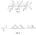
- einen Teilquerschnitt durch die Wandung eines Leuchtengehäuses, die Aufnahmen aufweist, in die Leuchtdioden eingesetzt sind,
- Fig. 5
- eine Seitenansicht eines als Starflex-Leiterplatte ausgebildeten Leiterbahnträgers, der mit konventionellen Leuchtdioden und mit SMT-Leuchtdioden bestückt ist und
- Fig. 6
- eine Aufsicht auf einen Teilbereich eines flexiblen Leiterbahnträgers, auf dem Leuchtdioden und weitere elektronische Bauelemente angeordnet sind.
- Eine im ganzen mit 1 bezeichnete Kraftfahrzeugleuchte weist ein Leuchtengehäuse 2 auf, in dem mehrere Leuchtdioden 3a, 3b auf einem als flexible Trägerfolie ausgebildeten Leiterbahnträgern 4 angeordnet sind. Die Trägerfolie weist in der Zeichnung nicht dargestellte Leiterbahnen zur Stromversorgung der Leuchtdioden 3a, 3b auf, die mit Anschlusskontakten der Leuchtdioden 3a, 3b verbunden sind. In Fig. 1, 4 und 5 ist erkennbar, dass jeweils mehrere der Leuchtdioden 3a formschlüssig in an dem Leuchtengehäuse 2 vorgesehene Aufnahmen 5 eingreifen. Über diese Leuchtdioden 3a ist der Leiterbahnträger 4 an dem Leuchtengehäuse 2 befestigt.
- Die Aufnahmen 5 sind jeweils als Steckaufnahmen ausgebildet, in welche die Leuchtdioden 3a aus einer Vormontagestellung in der jeweils durch den Pfeil Pf1 markierten Einsteckrichtung einsteckbar sind. Die Leuchtdioden 3a weisen an ihrem dem Leiterbahnträger 4 zugewandten Gehäuseende jeweils einen Ringbund auf, der in Montagestellung der Leuchtdioden 3a an einem an der Aufnahme 5 vorgesehenen, dem Ringbund zugewandten Anschlag anliegt.
- Bei der Herstellung der Kraftfahrzeugleuchte 1 werden die Leuchtdioden 3a, 3d bei in Flachlage befindlichem Leiterbahnträger 4 (Fig. 2) auf diesen montiert und danach wird der Leiterbahnträger 4 mit den darauf befindlichen Leuchtdioden 3a, 3b in den Aufnahmebereich 6 des Leuchtengehäuses 2 eingesetzt, wobei die Leuchtdioden 3a in die Aufnahmen 5 eingesteckt werden. Die Kraftfahrzeugleuchte 1 ist somit einfach und kostengünstig montierbar.
- In Fig. 2 und 3 ist erkennbar, dass die Trägerfolie einen zentralen Bereich aufweist, in dem mehrere in SMT-Technik ausgebildete Leuchtdioden 3b angeordnet sind. In Fig. 3 sind diese Leuchtdioden 3b jeweils durch Kreuze schematisch angedeutet. Beidseits des zentralen Bereichs ist jeweils eine laschenförmige Fortsetzung 7 der Trägerfolie vorgesehen, die benachbart zu ihrem dem zentralen Bereich abgewandten freien Ende jeweils eine konventionelle Leuchtdiode 3a trägt. In Fig. 3 ist erkennbar, dass diese laschenförmigen Fortsetzungen diametral gegenüberliegend mit ihren Erstreckungsrichtungen etwa radial zum Zentrum des zentralen Bereichs der Trägerfolie angeordnet sind. Wie in Fig. 2 besonders gut erkennbar ist, sind die an den laschenförmigen Fortsetzungen 7 befindlichen Leuchtdioden 3a jeweils an der den Leuchtdioden 3b des zentralen Bereichs abgewandten Rückseite der Trägerfolie angeordnet.
- Fig. 1 zeigt die Trägerfolie in Montagestellung. Deutlich ist erkennbar, dass die Leuchtdioden 3a der laschenförmigen Fortsetzungen 7 in an den Seitenwandungen 8 des im Querschnitt U-förmigen Aufnahmebereichs 6 des Leuchtengehäuses 2 angeordneten Aufnahmen 5 eingesetzt sind. Diese Aufnahme 5 sind durch Lochungen gebildet, welche die Seitenwand 8 des U-förmigen Aufnahmebereichs 6 durchsetzen. Dabei sind die Leuchtdioden 3a mit ihrer Lichtaustrittsfläche an dem der Trägerfolie abgewandten Ende der Aufnahme 5 angeordnet, so dass sie an der dem Leiterbahnträger 4 abgewandten Rückseite der Seitenwandung Licht in einen seitlichen Bereich abstrahlen können. In Fig. 1 ist weiter erkennbar, dass der zentrale Bereich der Trägerfolie etwa parallel zum Boden des U-förmigen Aufnahmebereichs 6 angeordnet ist und rückseitig gegen diesen abgestützt ist bzw. an diesem anliegt. An der Vorderseite des zentralen Bereichs sind die Leuchtdioden 3b angeordnet, die mit ihrer Abstrahlrichtung etwa rechtwinklig zur Ebene des Bodens des U-förmigen Aufnahmebereichs 6 ausgerichtet sind.
- Bei dem Ausführungsbeispiel nach Fig. 4 sind die Aufnahmen 5 jeweils schräg zur Ebene der Wandung des Leuchtengehäuses 2 angeordnet. Deutlich ist erkennbar, dass die Aufnahmen 5 jeweils als Durchgangslochung ausgebildet sind, und dass diese Durchgangslochungen mit ihren Achsen jeweils parallel zueinander angeordnet sind.
- Bei dem Ausführungsbeispiel nach Fig. 5 weisen die Leiterbahnträger 4 einerseits flexible und andererseits aber auch weitgehend starre Bereiche auf. Dabei ist der zentrale Leiterplattenbereich jeweils starr ausgebildet, während die seitlich daran angeordneten Fortsetzungen flexibel sind. Deutlich ist erkennbar, dass der zentrale starre Bereich des Leiterbahnträgers 4 eine größere Dicke aufweist als die flexiblen Fortsetzungen. Selbstverständlich sind auch beliebige andere Anordnungen von miteinander verbundenen starren und flexiblen Leiterbahnträgern denkbar, beispielsweise eine Anordnung, bei welcher der flexible Bereich mittig und die starren Bereiche an den Rändern des Leiterbahnträgers 4 vorgesehen sind.
- Bei dem Ausführungsbeispiel nach Fig. 5 sind die Leuchtdioden 3b bei einem der beidseits des zentralen Leiterbahnträgerbereichs angeordneten Fortsetzungen 7 an der Vorderseite und bei der anderen Fortsetzung 7 an der Rückseite des Leiterbahnträgers 4 angeordnet sind.
- Dabei ist nicht dargestellt, dass an einer Seite des zentralen Leiterplattenbereichs mehrere laschenartige Fortsetzungen vorgesehen sein können, die quer zu ihrer Erstreckungsrichtung nebeneinander angeordnet sind. In Montagestellung können derartige mehrere Fortsetzungen 7 in unterschiedlichen Winkeln gegenüber der Ebene des zentralen Bereichs geneigt sein, wodurch eine gewünschte Lichtverteilung ohne die Verwendung mehrerer optischer Bauteile, wie zum Beispiel Linsen oder Umlenkspiegeln, erreicht werden kann.
- Bei dem in Fig. 6 gezeigten Ausführungsbeispiel weist die Trägerfolie zwei Teilbereiche 9 auf, die durch einen mäanderförmigen, geschlitzten Bereich 10 der Trägerfolie miteinander verbunden sind. In jedem der Teilbereiche 10 ist jeweils eine Gruppe mit mehreren Leuchtdioden 3a angeordnet. Mittels des geschlitzten Bereichs 10 können die beiden Teilbereiche 9 der Trägerfolie in der Ebene der Trägerfolie quer zur Erstreckungsrichtung der Schlitze aus einer Ruhelage aufeinander zu- und voneinander weg bewegt werden. Außerdem können die Teilbereiche 10 in Erstreckungsrichtung der Schlitze gegeneinander verschoben werden. Der mäanderförmige Bereich 10 ermöglicht es aber auch, die Teilbereiche 9 der Trägerfolie mit ihren Ebenen gegeneinander zu verschwenken.
- In Fig. 6 ist noch erkennbar, dass zusätzlich zu den Leuchtdioden 3a auf der Trägerfolie eine in der Zeichnung nur schematisch dargestellte Steuerelektronik 11mit einem Temperaturfühler 12 angeordnet ist. Die Steuerelektronik 11 weist eine Stromsteuerschaltung für die Leuchtdioden 3a auf, die über Leiterbahnen einerseits mit dem Temperaturfühler 12 und andererseits mit den elektrischen Anschlüssen der Leuchtdioden 3a verbunden ist. Mittels der Stromsteuerschaltung wird der Betriebsstrom der Leuchtdioden 3a in Abhängigkeit von der Umgebungstemperatur gesteuert. Oberhalb einer vorgegebenen Grenztemperatur wird der Betriebsstrom der Leuchtdiode 3a mit zunehmender Temperatur reduziert. Dabei kann die Reduzierung des Betriebsstroms in Stufen oder kontinuierlich erfolgen. Unterhalb der Grenztemperatur werden die Leuchtdioden mit einem konstanten Betriebsstrom bestromt.
- In Fig. 1 ist noch erkennbar, dass das Leuchtengehäuse 2 lichtabstrahlseitig eine optisch transparente Lichtscheibe 13 aufweist. In die Lichtscheibe 13 können gegebenenfalls optische Streuelemente integriert sein.
Claims (6)
- Kraftfahrzeugleuchte (1) mit einem Leuchtengehäuse (2), in dem mehrere Leuchtdioden (3a, 3b) auf zumindest einem mit Anschlusskontakten der Leuchtdioden (3a, 3b) verbundene elektrische Leiterbahnen aufweisenden Leiterbahnträger (4) angeordnet sind, wobei wenigstens eine der Leuchtdioden (3a, 3b) formschlüssig in eine an dem Leuchtengehäuse (2) vorgesehenen Aufnahme (5) eingreift, dadurch gekennzeichnet, dass der Leiterbahnträger (4) zumindest bereichsweise als flexible Trägerfolie ausgebildet ist und dass an beiden der einander abgewandten Flachseiten der Trägerfolie jeweils wenigstens eine Leuchtdiode (3a, 3b) angeordnet ist.
- Kraftfahrzeugleuchte (1) nach Anspruch 1, dadurch gekennzeichnet, dass die Aufnahme (5) als Steckaufnahme ausgebildet ist, in welche die Leuchtdiode (3a, 3b) aus einer Vormontagestellung in Einsteckrichtung (Pf1) einsteckbar und vorzugsweise gegen einen an dem Leuchtengehäuse (2) vorgesehenen Anschlag in Montagestellung positionierbar ist.
- Kraftfahrzeugleuchte (1) nach einem der Ansprüche 1 oder 2, dadurch gekennzeichnet, dass die Trägerfolie einen zentralen Bereich aufweist, in dem vorzugsweise mehrere Leuchtdioden (3a, 3b) angeordnet sind, dass beidseits des zentralen Bereichs jeweils wenigstens eine insbesondere laschenförmige Fortsetzung (7) der Trägerfolie vorgesehen ist, dass an dieser Fortsetzung (7) jeweils wenigstens eine Leuchtdiode angeordnet ist, und dass die Fortsetzungen zur Ausleuchtung seitlicher Bereiche in Gebrauchsstellung vorzugsweise aus der Flachlage verschwenkt sind.
- Kraftfahrzeugleuchte (1) nach einem der Ansprüche 1 bis 3, dadurch gekennzeichnet, dass das Leuchtengehäuse einen im Querschnitt etwa U-förmigen Aufnahmebereich (6) aufweist, in dem die Trägerfolie etwa U-förmig angeordnet ist, und dass an den einander gegenüberliegenden Seitenwandungen (8) dieses Aufnahmebereichs jeweils wenigstens eine als Durchgangslochung ausgebildete Aufnahme (5) vorgesehen ist, in die eine auf der Trägerfolie angeordnete Leuchtdiode (3a) formschlüssig eingesetzt ist.
- Kraftfahrzeugleuchte (1) nach einem der Ansprüche 1 bis 4, dadurch gekennzeichnet, dass die Trägerfolie wenigstens zwei Teilbereiche (9) aufweist, in denen jeweils wenigstens eine Leuchtdiode (3a, 3b) angeordnet ist und dass diese Teilbereiche (9) durch einen mäanderförmigen, geschlitzten Bereich (10) der Trägerfolie miteinander verbunden sind.
- Kraftfahrzeugleuchte (1) nach einem der Ansprüche 1 bis 5, dadurch gekennzeichnet, dass zusätzlich zu den Leuchtdioden (3a, 3b) wenigstens ein weiteres elektronisches Bauelement auf der Trägerfolie angeordnet ist und dass dieses Bauelement insbesondere Teil einer Steuerelektronik (11) zum Ansteuern der Leuchtdioden (3a, 3b) ist.
Applications Claiming Priority (2)
| Application Number | Priority Date | Filing Date | Title |
|---|---|---|---|
| DE29919817U DE29919817U1 (de) | 1999-11-11 | 1999-11-11 | Kraftfahrzeugleuchte |
| DE29919817U | 1999-11-11 |
Publications (3)
| Publication Number | Publication Date |
|---|---|
| EP1099601A2 EP1099601A2 (de) | 2001-05-16 |
| EP1099601A3 EP1099601A3 (de) | 2002-04-10 |
| EP1099601B1 true EP1099601B1 (de) | 2007-08-01 |
Family
ID=8081479
Family Applications (1)
| Application Number | Title | Priority Date | Filing Date |
|---|---|---|---|
| EP00123767A Expired - Lifetime EP1099601B1 (de) | 1999-11-11 | 2000-11-01 | Kraftfahrzeugleuchte |
Country Status (3)
| Country | Link |
|---|---|
| EP (1) | EP1099601B1 (de) |
| DE (2) | DE29919817U1 (de) |
| ES (1) | ES2291164T3 (de) |
Families Citing this family (19)
| Publication number | Priority date | Publication date | Assignee | Title |
|---|---|---|---|---|
| DE19909399C1 (de) * | 1999-03-04 | 2001-01-04 | Osram Opto Semiconductors Gmbh | Flexibles LED-Mehrfachmodul, insb. für ein Leuchtengehäuse eines Kraftfahrzeuges |
| DE20002565U1 (de) * | 2000-02-14 | 2001-06-28 | Zumtobel Staff Ges.M.B.H., Dornbirn | Leuchtdiodenanordnung mit Reflektor |
| DE10020099A1 (de) * | 2000-04-22 | 2001-10-25 | Hella Kg Hueck & Co | Kraftfahrzeugleuchte |
| DE10034767A1 (de) * | 2000-07-18 | 2002-05-02 | Hella Kg Hueck & Co | Leuchte |
| EP3168625B1 (de) * | 2000-11-20 | 2020-01-08 | Signify North America Corporation | Fahrzeugleuchtensysteme |
| DE10058660B4 (de) * | 2000-11-25 | 2009-07-30 | Volkswagen Ag | Kraftfahrzeugleuchte |
| DE10108073B4 (de) * | 2001-02-20 | 2012-02-09 | Delphi Technologies, Inc. | Leuchtvorrichtung |
| TW546224B (en) * | 2001-09-03 | 2003-08-11 | Honda Motor Co Ltd | LED lighting device for vehicles |
| DE10225543A1 (de) * | 2002-06-10 | 2003-12-18 | Hella Kg Hueck & Co | Träger für Leuchtelemente in einer Kraftfahrzeugleuchte |
| EP1411290A1 (de) * | 2002-10-18 | 2004-04-21 | Altman Stage Lighting Co.,Inc. New York Corporation | Beleuchtungssytem mit Leuchtdioden |
| DE10254662B4 (de) * | 2002-11-22 | 2005-08-04 | Osram Opto Semiconductors Gmbh | Montageträger für Lichtemissionsdioden, Verfahren zum Montieren von Lichtemissionsdioden, flexibles Lichtemissionsdioden-Modul und Verfahren zur Herstellung desselben |
| DE10255709A1 (de) * | 2002-11-29 | 2004-06-09 | Hella Kg Hueck & Co. | Fahrzeugleuchte |
| DE102004023358B3 (de) * | 2004-05-12 | 2006-04-06 | Michael Smit | Leuchte, insbesondere Einbau- oder Aufbauleuchte |
| DE102004054822A1 (de) * | 2004-11-13 | 2006-05-18 | Schefenacker Vision Systems Germany Gmbh | Leuchte für Fahrzeuge, vorzugsweise für Kraftfahrzeuge |
| DE102007041335A1 (de) | 2007-08-31 | 2009-03-05 | Siemens Ag Österreich | Vorrichtung zur Anordnung von LED-Leuchten |
| JP4982808B2 (ja) * | 2008-03-19 | 2012-07-25 | 本田技研工業株式会社 | 車両用灯火装置 |
| DE102008039071B4 (de) | 2008-08-21 | 2024-05-02 | HELLA GmbH & Co. KGaA | Beleuchtungsvorrichtung für Fahrzeuge |
| DE102009009288A1 (de) * | 2009-02-17 | 2010-08-26 | Osram Gesellschaft mit beschränkter Haftung | Starrflexible Trägerplatte |
| WO2019237064A1 (en) * | 2018-06-08 | 2019-12-12 | Quarkstar Llc | Modular luminaire with heat-conductive coupled modules |
Family Cites Families (9)
| Publication number | Priority date | Publication date | Assignee | Title |
|---|---|---|---|---|
| US4173035A (en) | 1977-12-01 | 1979-10-30 | Media Masters, Inc. | Tape strip for effecting moving light display |
| US5038255A (en) * | 1989-09-09 | 1991-08-06 | Stanley Electric Co., Ltd. | Vehicle lamp |
| FR2680860B1 (fr) * | 1991-09-02 | 1997-07-04 | Valeo Vision | Element de support, notamment pour feu de signalisation de vehicule automobile et son procede de fabrication. |
| US5325271A (en) * | 1992-06-10 | 1994-06-28 | Dominion Automotive Industries Corp. | Marker lamp with LED array and prismatic diffuser |
| US5404282A (en) | 1993-09-17 | 1995-04-04 | Hewlett-Packard Company | Multiple light emitting diode module |
| DE4412772A1 (de) * | 1994-04-14 | 1995-10-19 | Airsigna Gmbh & Co Kg | Beleuchtungseinrichtung insbesondere Notbeleuchtungseinrichtung für das Innere von Wasserfahrzeugen |
| US5519596A (en) | 1995-05-16 | 1996-05-21 | Hewlett-Packard Company | Moldable nesting frame for light emitting diode array |
| DE19621148A1 (de) | 1996-05-14 | 1997-12-04 | Magna Reflex Holding Gmbh | Leuchtelement |
| DE19734748A1 (de) | 1997-08-12 | 1999-02-18 | Reitter & Schefenacker Gmbh | Träger, vorzugsweise für Heckleuchten von Kraftfahrzeugen, sowie Verfahren zur Befestigung von elektronischen Bauteilen, vorzugsweise von LED's, an einem solchen Träger |
-
1999
- 1999-11-11 DE DE29919817U patent/DE29919817U1/de not_active Expired - Lifetime
-
2000
- 2000-11-01 EP EP00123767A patent/EP1099601B1/de not_active Expired - Lifetime
- 2000-11-01 DE DE50014525T patent/DE50014525D1/de not_active Expired - Fee Related
- 2000-11-01 ES ES00123767T patent/ES2291164T3/es not_active Expired - Lifetime
Non-Patent Citations (1)
| Title |
|---|
| None * |
Also Published As
| Publication number | Publication date |
|---|---|
| DE29919817U1 (de) | 2000-01-05 |
| ES2291164T3 (es) | 2008-03-01 |
| EP1099601A2 (de) | 2001-05-16 |
| DE50014525D1 (de) | 2007-09-13 |
| EP1099601A3 (de) | 2002-04-10 |
Similar Documents
| Publication | Publication Date | Title |
|---|---|---|
| EP1099601B1 (de) | Kraftfahrzeugleuchte | |
| EP1405377B1 (de) | Led-modul für beleuchtungsvorrichtungen | |
| EP1069371B1 (de) | Leuchtdiodenanordnung | |
| EP2317213B1 (de) | Leuchtdiodenmodul einer Kraftfahrzeugbeleuchtungseinrichtung und Kraftfahrzeugbeleuchtungseinrichtung | |
| EP2057406B1 (de) | Lampe mit einem sockel und mindestens einem lichtemittierenden halbleiterbauelement | |
| EP1852306B1 (de) | Leuchte mit wenigstens einer Leuchtmitteleinheit für Fahrzeuge, vorzugsweise für Kraftfahrzeuge | |
| DE102016121047A1 (de) | Beleuchtungseinrichtung für ein fahrzeug sowie herstellungsverfahren für eine beleuchtungseinrichtung | |
| DE102016112331A1 (de) | Lichtquelleneinheit, Beleuchtungsvorrichtung und Fahrzeug | |
| EP2347639B1 (de) | Beleuchtungsvorrichtung mit zwei leiterplatten | |
| EP2651695A1 (de) | Vorrichtung zur innenbeleuchtung in einem kraftfahrzeug | |
| DE10016714A1 (de) | Strahlungsemittierende Vorrichtung | |
| EP0799406B1 (de) | Anzeigeinstrument | |
| DE102020110237B4 (de) | Steckverbinderanordnung und verfahren zur herstellung einer steckverbinderanordnung | |
| DE102008048835B4 (de) | Fixierungssystem zum lösbaren Fixieren einer Lichtquelle an einer Lichteintrittsfläche eines Lichtleitkörpers und zugehöriges Innenausstattungspaneel | |
| DE102005027530B4 (de) | Beleuchtungsmodul für die Hinterleuchtung und Ausleuchtung von hohlen Stellrädern, Markierungen oder zur Funktionsanzeige | |
| WO2020152039A1 (de) | Beleuchtungseinheit, beleuchtbares bauteil und verfahren zu dessen herstellung | |
| DE4036541A1 (de) | Halte- und anschlussvorrichtung fuer eine leuchtdiode | |
| EP2290281A2 (de) | Leuchtmittel sowie Leuchte | |
| DE102008004483A1 (de) | Flexible Leuchtmittelbaugruppe für Fahrzeugleuchten | |
| DE19644995A1 (de) | Anzeigeinstrument mit einem beleuchtbaren Anzeigefeld | |
| DE4410771B4 (de) | Schalter, insbesondere in die Armaturentafel eines Kraftfahrzeuges einbaubarer Schalter, sowie Verfahren zum Herstellen eines Schalters | |
| DE102004044544A1 (de) | Vorrichtung zur Beleuchtung der Bedienungsblende einer Waschmaschine über das Elektronikgehäuse | |
| DE102018010157A1 (de) | Elektronisches Gerät, Baugruppe mit dem Gerät, Verfahren zum Montieren des Geräts und Verfahren zum Montieren der Baugruppe | |
| DE102018118478A1 (de) | Verfahren zur Herstellung einer beleuchtbaren Baugruppe und beleuchtbare Baugruppe | |
| DE60033263T2 (de) | Träger für Autonomen Notlichtblock und Autonomer Block mit einem solchen Träger |
Legal Events
| Date | Code | Title | Description |
|---|---|---|---|
| PUAI | Public reference made under article 153(3) epc to a published international application that has entered the european phase |
Free format text: ORIGINAL CODE: 0009012 |
|
| AK | Designated contracting states |
Kind code of ref document: A2 Designated state(s): AT BE CH CY DE DK ES FI FR GB GR IE IT LI LU MC NL PT SE TR Kind code of ref document: A2 Designated state(s): AT BE CH CY DE LI |
|
| AX | Request for extension of the european patent |
Free format text: AL;LT;LV;MK;RO;SI |
|
| PUAL | Search report despatched |
Free format text: ORIGINAL CODE: 0009013 |
|
| AK | Designated contracting states |
Kind code of ref document: A3 Designated state(s): AT BE CH CY DE DK ES FI FR GB GR IE IT LI LU MC NL PT SE TR |
|
| AX | Request for extension of the european patent |
Free format text: AL;LT;LV;MK;RO;SI |
|
| AKX | Designation fees paid | ||
| 17P | Request for examination filed |
Effective date: 20021116 |
|
| RBV | Designated contracting states (corrected) |
Designated state(s): AT BE CH CY DE LI |
|
| RBV | Designated contracting states (corrected) |
Designated state(s): DE ES FR GB IT |
|
| REG | Reference to a national code |
Ref country code: DE Ref legal event code: 8566 |
|
| RAP1 | Party data changed (applicant data changed or rights of an application transferred) |
Owner name: HELLA KGAA HUECK & CO. |
|
| 17Q | First examination report despatched |
Effective date: 20061107 |
|
| GRAP | Despatch of communication of intention to grant a patent |
Free format text: ORIGINAL CODE: EPIDOSNIGR1 |
|
| GRAS | Grant fee paid |
Free format text: ORIGINAL CODE: EPIDOSNIGR3 |
|
| GRAA | (expected) grant |
Free format text: ORIGINAL CODE: 0009210 |
|
| AK | Designated contracting states |
Kind code of ref document: B1 Designated state(s): DE ES FR GB IT |
|
| REG | Reference to a national code |
Ref country code: GB Ref legal event code: FG4D Free format text: NOT ENGLISH |
|
| REF | Corresponds to: |
Ref document number: 50014525 Country of ref document: DE Date of ref document: 20070913 Kind code of ref document: P |
|
| ET | Fr: translation filed | ||
| PGFP | Annual fee paid to national office [announced via postgrant information from national office to epo] |
Ref country code: ES Payment date: 20071219 Year of fee payment: 8 Ref country code: DE Payment date: 20071025 Year of fee payment: 8 |
|
| GBV | Gb: ep patent (uk) treated as always having been void in accordance with gb section 77(7)/1977 [no translation filed] |
Effective date: 20070801 |
|
| REG | Reference to a national code |
Ref country code: ES Ref legal event code: FG2A Ref document number: 2291164 Country of ref document: ES Kind code of ref document: T3 |
|
| PGFP | Annual fee paid to national office [announced via postgrant information from national office to epo] |
Ref country code: FR Payment date: 20071108 Year of fee payment: 8 |
|
| PG25 | Lapsed in a contracting state [announced via postgrant information from national office to epo] |
Ref country code: GB Free format text: LAPSE BECAUSE OF FAILURE TO SUBMIT A TRANSLATION OF THE DESCRIPTION OR TO PAY THE FEE WITHIN THE PRESCRIBED TIME-LIMIT Effective date: 20070801 |
|
| PLBE | No opposition filed within time limit |
Free format text: ORIGINAL CODE: 0009261 |
|
| STAA | Information on the status of an ep patent application or granted ep patent |
Free format text: STATUS: NO OPPOSITION FILED WITHIN TIME LIMIT |
|
| 26N | No opposition filed |
Effective date: 20080506 |
|
| REG | Reference to a national code |
Ref country code: FR Ref legal event code: ST Effective date: 20090731 |
|
| PG25 | Lapsed in a contracting state [announced via postgrant information from national office to epo] |
Ref country code: DE Free format text: LAPSE BECAUSE OF NON-PAYMENT OF DUE FEES Effective date: 20090603 |
|
| REG | Reference to a national code |
Ref country code: ES Ref legal event code: FD2A Effective date: 20081103 |
|
| PG25 | Lapsed in a contracting state [announced via postgrant information from national office to epo] |
Ref country code: ES Free format text: LAPSE BECAUSE OF NON-PAYMENT OF DUE FEES Effective date: 20081103 |
|
| PG25 | Lapsed in a contracting state [announced via postgrant information from national office to epo] |
Ref country code: IT Free format text: LAPSE BECAUSE OF NON-PAYMENT OF DUE FEES Effective date: 20071130 |
|
| PG25 | Lapsed in a contracting state [announced via postgrant information from national office to epo] |
Ref country code: FR Free format text: LAPSE BECAUSE OF NON-PAYMENT OF DUE FEES Effective date: 20081130 |