EP1069371B1 - Leuchtdiodenanordnung - Google Patents
Leuchtdiodenanordnung Download PDFInfo
- Publication number
- EP1069371B1 EP1069371B1 EP00113959A EP00113959A EP1069371B1 EP 1069371 B1 EP1069371 B1 EP 1069371B1 EP 00113959 A EP00113959 A EP 00113959A EP 00113959 A EP00113959 A EP 00113959A EP 1069371 B1 EP1069371 B1 EP 1069371B1
- Authority
- EP
- European Patent Office
- Prior art keywords
- light emitting
- emitting diodes
- base plate
- pair
- contact pins
- Prior art date
- Legal status (The legal status is an assumption and is not a legal conclusion. Google has not performed a legal analysis and makes no representation as to the accuracy of the status listed.)
- Expired - Lifetime
Links
Images

Classifications
-
- H—ELECTRICITY
- H05—ELECTRIC TECHNIQUES NOT OTHERWISE PROVIDED FOR
- H05K—PRINTED CIRCUITS; CASINGS OR CONSTRUCTIONAL DETAILS OF ELECTRIC APPARATUS; MANUFACTURE OF ASSEMBLAGES OF ELECTRICAL COMPONENTS
- H05K1/00—Printed circuits
- H05K1/18—Printed circuits structurally associated with non-printed electric components
- H05K1/182—Printed circuits structurally associated with non-printed electric components associated with components mounted in printed circuit boards [PCB], e.g. insert-mounted components [IMC]
-
- B—PERFORMING OPERATIONS; TRANSPORTING
- B60—VEHICLES IN GENERAL
- B60Q—ARRANGEMENT OF SIGNALLING OR LIGHTING DEVICES, THE MOUNTING OR SUPPORTING THEREOF OR CIRCUITS THEREFOR, FOR VEHICLES IN GENERAL
- B60Q1/00—Arrangement of optical signalling or lighting devices, the mounting or supporting thereof or circuits therefor
- B60Q1/26—Arrangement of optical signalling or lighting devices, the mounting or supporting thereof or circuits therefor the devices being primarily intended to indicate the vehicle, or parts thereof, or to give signals, to other traffic
- B60Q1/2696—Mounting of devices using LEDs
-
- F—MECHANICAL ENGINEERING; LIGHTING; HEATING; WEAPONS; BLASTING
- F21—LIGHTING
- F21S—NON-PORTABLE LIGHTING DEVICES; SYSTEMS THEREOF; VEHICLE LIGHTING DEVICES SPECIALLY ADAPTED FOR VEHICLE EXTERIORS
- F21S43/00—Signalling devices specially adapted for vehicle exteriors, e.g. brake lamps, direction indicator lights or reversing lights
- F21S43/10—Signalling devices specially adapted for vehicle exteriors, e.g. brake lamps, direction indicator lights or reversing lights characterised by the light source
- F21S43/13—Signalling devices specially adapted for vehicle exteriors, e.g. brake lamps, direction indicator lights or reversing lights characterised by the light source characterised by the type of light source
- F21S43/14—Light emitting diodes [LED]
-
- F—MECHANICAL ENGINEERING; LIGHTING; HEATING; WEAPONS; BLASTING
- F21—LIGHTING
- F21V—FUNCTIONAL FEATURES OR DETAILS OF LIGHTING DEVICES OR SYSTEMS THEREOF; STRUCTURAL COMBINATIONS OF LIGHTING DEVICES WITH OTHER ARTICLES, NOT OTHERWISE PROVIDED FOR
- F21V19/00—Fastening of light sources or lamp holders
- F21V19/001—Fastening of light sources or lamp holders the light sources being semiconductors devices, e.g. LEDs
- F21V19/0015—Fastening arrangements intended to retain light sources
- F21V19/0025—Fastening arrangements intended to retain light sources the fastening means engaging the conductors of the light source, i.e. providing simultaneous fastening of the light sources and their electric connections
-
- H—ELECTRICITY
- H10—SEMICONDUCTOR DEVICES; ELECTRIC SOLID-STATE DEVICES NOT OTHERWISE PROVIDED FOR
- H10W—GENERIC PACKAGES, INTERCONNECTIONS, CONNECTORS OR OTHER CONSTRUCTIONAL DETAILS OF DEVICES COVERED BY CLASS H10
- H10W90/00—Package configurations
-
- F—MECHANICAL ENGINEERING; LIGHTING; HEATING; WEAPONS; BLASTING
- F21—LIGHTING
- F21Y—INDEXING SCHEME ASSOCIATED WITH SUBCLASSES F21K, F21L, F21S and F21V, RELATING TO THE FORM OR THE KIND OF THE LIGHT SOURCES OR OF THE COLOUR OF THE LIGHT EMITTED
- F21Y2107/00—Light sources with three-dimensionally disposed light-generating elements
- F21Y2107/50—Light sources with three-dimensionally disposed light-generating elements on planar substrates or supports, but arranged in different planes or with differing orientation, e.g. on plate-shaped supports with steps on which light-generating elements are mounted
-
- F—MECHANICAL ENGINEERING; LIGHTING; HEATING; WEAPONS; BLASTING
- F21—LIGHTING
- F21Y—INDEXING SCHEME ASSOCIATED WITH SUBCLASSES F21K, F21L, F21S and F21V, RELATING TO THE FORM OR THE KIND OF THE LIGHT SOURCES OR OF THE COLOUR OF THE LIGHT EMITTED
- F21Y2115/00—Light-generating elements of semiconductor light sources
- F21Y2115/10—Light-emitting diodes [LED]
-
- Y—GENERAL TAGGING OF NEW TECHNOLOGICAL DEVELOPMENTS; GENERAL TAGGING OF CROSS-SECTIONAL TECHNOLOGIES SPANNING OVER SEVERAL SECTIONS OF THE IPC; TECHNICAL SUBJECTS COVERED BY FORMER USPC CROSS-REFERENCE ART COLLECTIONS [XRACs] AND DIGESTS
- Y10—TECHNICAL SUBJECTS COVERED BY FORMER USPC
- Y10S—TECHNICAL SUBJECTS COVERED BY FORMER USPC CROSS-REFERENCE ART COLLECTIONS [XRACs] AND DIGESTS
- Y10S362/00—Illumination
- Y10S362/80—Light emitting diode
Definitions
- the invention relates to a light-emitting diode arrangement according to the preamble of patent claim 1.
- the invention further relates to a method for the oblique arrangement of a plurality of light-emitting diodes on a carrier plate.
- the problem is that often a radiation direction is desired, which is not oriented perpendicular to a ground plane, but which is oriented obliquely relative to the ground plane.
- a motor vehicle lamp in which a plurality of light-emitting diodes are arranged obliquely with their emission direction relative to a ground plane.
- the light emitting diodes are arranged on carrier plates, wherein their emission direction is arranged perpendicular to the plane of the carrier plate.
- the light-emitting diodes have base bodies which are fastened with their contact pins in guide bores of the carrier plate.
- a lighting device for vehicles in which the emission direction of light emitting diodes, which are arranged on a spatially curved support plate, is deflected by special upstream deflection elements.
- JP 05152610 A is a light emitting diode array with light-emitting diodes known, the main body are each arranged inclined to a support plate.
- the light-emitting diodes each have contact pins which engage in guide bores of the carrier plate. An intrusion of the main body of the light emitting diode in the plane of the support plate is not provided.
- Object of the present invention is therefore to improve the known light-emitting diode arrays so that the desired oblique orientation of the emission is achieved easily and inexpensively by reducing the depth.
- the support plate can be arranged parallel to the ground plane and only the light emitting diodes are arranged with its body obliquely on the support plate, the support plate can be easier and cheaper to arrange in a surrounding housing. It is also possible to make do with only one support plate or at least with fewer support plates than before. The required installation depth is also significantly reduced in this solution.
- the base body at its the support plate at a distance adjacent the first end a first pair of contact pins, the free ends are mounted in contact holes of the support plate, wherein the base body has at its second end opposite the first end a second pair of contact legs which mechanically holds the base body relative to the support plate.
- the support plate has an opening into which the base body projects so far with its second end, that its support plate facing bottom preferably abuts against the contact holes facing rear inner edge of the opening.
- the second pair of contact legs with its free ends on an underside of the carrier plate.
- the depth decreases further.
- the angle of inclination of the light-emitting diode is determined by the width of the aperture or by the arrangement of the rear inner edge.
- the LEDs are aligned in different directions of radiation. It is basically possible to combine in a conventional manner arranged perpendicular to the support plate LEDs with diagonally arranged light-emitting diodes.
- the support plate on its side facing away from the light emitting diodes on a heat dissipation element.
- Another object of the invention is to improve the known method for oblique arrangement of the LEDs.
- the LEDs are used in a first operation with its arranged at a first end of a body first pair of contact pins in guide holes of the support plate, wherein the free ends of a remote from the first end second end disposed second contact pair protrude into an adjacent breakthrough that the LEDs are soldered in a second operation with their first pair of contact legs with the support plate that the LEDs are bent in a third operation so that the main body protrude with their second ends in the openings and with their strike the carrier plate facing lower sides to an inner edge of the opening, and that in a fourth operation, the free ends of the second pair of contact pins are bent against the underside of the support plate.
- the light emitting diodes are mounted obliquely on the support plate, can be dispensed with an oblique arrangement of the support plate.
- the operations according to the invention also make it possible to automate them.
- the LEDs can be mounted relatively easily and inexpensively.
- the required stability is achieved in a simple manner.
- the light-emitting diode arrangement according to the invention can be used for rear-mounted, flashing, side-marker and interior lights for motor vehicles.
- a light-emitting diode arrangement 1 essentially consists of a carrier plate 2 and a plurality of light-emitting diodes 3 or LEDs.
- the light-emitting diodes 3 have a main body 4, via the light exit surface 5 light is emitted.
- the emission direction 6 is arranged perpendicular to the main body surface 7.
- the base body On its underside 8 facing away from the base body surface 7, the base body has at its first end 9 a first pair of contact legs 10. At its second end 11 opposite the first end 9, the base body 7 has on its underside 8 a second pair of contact legs 12.
- the support plate 2 is arranged in or parallel to a ground plane 21.
- the support plate 2 has not shown interconnects and optionally also not shown electronic components for Control of the LEDs 3 on.
- the support plate 2 has for each light emitting diode 3 on two guide holes 13, in each of which the first pair of contact legs 10 is arranged.
- an opening 14 is disposed on the support plate 2, in which the adjacent base body 4 is immersed with its second end 11.
- the opening 14 has a rear inner edge 15 facing the guide bores 13, against which the base body 4 abuts with its underside 8.
- the second pair of contact legs 12 rests with its free ends 16 on an underside 17 of the support plate 2.
- the width of the opening 14 or the arrangement of the rear inner edge 15, together with the distance 18 from the support surface 19, determines the angle of inclination 20 formed by the emission direction 6 and support surface 19.
- an unillustrated heat dissipation element can be arranged, can be derived via the heat from the LEDs 3. While the first pair of contact pins 10 is used for mechanical support and for electrical contacting, the second pair of contact pins 12 is used only for mechanical support.
- the LEDs 3 are used in a first operation with their respective first pair of contact pins 10 and their free ends 22 in the guide holes 13 of the support plate 2.
- the second pair of contact legs 12 protrudes with its free ends 16 in the adjacent opening 14th
- the base body 4 are bent so that its second end protrudes into the adjacent opening 14 and they strike with their carrier plate 2 facing bottom 8 to the rear inner edge 15 of the opening 14.
Landscapes
- Engineering & Computer Science (AREA)
- General Engineering & Computer Science (AREA)
- Microelectronics & Electronic Packaging (AREA)
- Mechanical Engineering (AREA)
- Physics & Mathematics (AREA)
- Optics & Photonics (AREA)
- Led Device Packages (AREA)
- Non-Portable Lighting Devices Or Systems Thereof (AREA)
- Fastening Of Light Sources Or Lamp Holders (AREA)
- Led Devices (AREA)
Description
- Die Erfindung betrifft eine Leuchtdiodenanordnung nach dem Oberbegriff des Patentanspruchs 1.
- Die Erfindung betrifft weiterhin ein Verfahren zur schrägen Anordnung von einer Mehrzahl von Leuchtdioden auf einer Trägerplatte.
- Insbesondere bei Signalleuchten für Kraftfahrzeuge besteht das Problem, daß häufig eine Abstrahlrichtung gewünscht ist, die nicht senkrecht zu einer Grundebene orientiert ist, sondern die gegenüber der Grundebene schräg orientiert ist.
- Aus der
DE 297 20 060 U1 ist eine Kraftfahrzeugleuchte bekannt, bei der eine Mehrzahl von Leuchtdioden mit ihrer Abstrahlrichtung gegenüber einer Grundebene schräg angeordnet sind. Zu diesem Zweck sind die Leuchtdioden auf Trägerplatten angeordnet, wobei ihre Abstrahlrichtung senkrecht zur Ebene der Trägerplatte angeordnet ist. Die Leuchtdioden weisen Grundkörper auf, die mit ihren Kontaktbeinchen in Führungsbohrungen der Trägerplatte befestigt sind. - Nachteilig bei der bekannten Signalleuchte ist, daß zur Neigung der Abstrahlrichtung gegenüber der Grundebene die Trägerplatten gegenüber der Grundebene geneigt bzw. schräg angeordnet werden müssen. Dies führt zu einer relativ komplizierten und aufwendigen Halterung der Trägerplatten. Auch muß eine Mehrzahl von Trägerplatten verwendet werden.
- Weiterhin ist aus der
DE 196 46 042 A1 eine Beleuchtungseinrichtung für Fahrzeuge bekannt, bei der die Abstrahlrichtung von Leuchtdioden, die auf einer räumlich gebogenen Trägerplatte angeordnet sind, durch spezielle vorgelagerte Umlenkelemente umgelenkt wird. - Nachteilig dabei ist, daß die Anordnung von Umlenkelementen ebenfalls relativ aufwendig und teuer ist.
- Aus der
JP 05152610 A - Aufgabe der vorliegenden Erfindung ist es daher, die bekannten Leuchtdiodenanordnungen so zu verbessern, daß die gewünschte schräge Orientierung der Abstrahlrichtung einfach und kostengünstig unter Verringerung der Bautiefe erreicht wird.
- Diese Aufgabe wird erfindungsgemäß durch die Merkmale des Patenanspruchs 1 gelöst.
- Dadurch, daß die Trägerplatte parallel zu der Grundebene angeordnet werden kann und lediglich die Leuchtdioden mit ihrem Grundkörper schräg auf der Trägerplatte angeordnet sind, läßt sich die Trägerplatte einfacher und kostengünstiger in einem sie umgebenden Gehäuse anordnen. Auch ist es möglich, nur mit einer Trägerplatte oder zumindest mit weniger Trägerplatten als bisher auszukommen. Die benötigte Einbautiefe wird bei dieser Lösung zudem erheblich verringert. Nach der Erfindung weist der Grundkörper an seinem der Trägerplatte in einem Abstand benachbarten ersten Ende ein erstes Paar von Kontaktbeinchen auf, deren freie Enden in Kontaktbohrungen der Trägerplatte befestigt sind, wobei der Grundkörper an seinem dem ersten Ende gegenüberliegenden zweiten Ende ein zweites Paar von Kontaktbeinchen aufweist, das den Grundkörper gegenüber der Trägerplatte mechanisch hält. Dabei weist die Trägerplatte einen Durchbruch auf, in den der Grundkörper mit seinem zweiten Ende so weit hineinragt, daß seine der Trägerplatte zugewandte Unterseite vorzugsweise gegen eine den Kontaktbohrungen zugewandte hintere Innenkante des Durchbruchs anschlägt.
- Gemäß einer bevorzugten Ausführungsform der Erfindung liegt das zweite Paar von Kontaktbeinchen mit seinen freien Enden an einer Unterseite der Trägerplatte an. Dadurch, daß der Grundkörper mit seinem zweiten Ende in einen Durchbruch der Trägerplatte hineinragt, verringert sich die Bautiefe weiter. Durch die Abstützung des Grundkörpers auf der Innenkante des Durchbruchs und durch das Anliegen der freien Enden des zweiten Paares von Kontaktbeinchen an der Unterseite der Trägerplatte wird zudem eine relativ gute Stabilität erreicht, die ein unerwünschtes Vibrieren bzw. Erschüttern der Leuchtdioden verhindert.
- Nach einer weiteren bevorzugten Ausführungsform der Erfindung wird der Neigungswinkel der Leuchtdiode durch die Breite des Durchbruchs bzw. durch die Anordnung der hinteren Innenkante bestimmt. Dadurch können auf einfache Weise unterschiedliche Abstrahlrichtungen erzielt werden.
- Gemäß einer weiteren bevorzugten Ausführungsform der Erfindung sind die Leuchtdioden in unterschiedlichen Abstrahlrichtungen ausgerichtet. Es ist grundsätzlich möglich, in herkömmlicher Weise senkrecht auf der Trägerplatte angeordnete Leuchtdioden mit schräg angeordneten Leuchtdioden zu kombinieren.
- Nach einer weiteren bevorzugten Ausführungsform der Erfindung weist die Trägerplatte auf ihrer den Leuchtdioden abgewandten Unterseite ein Wärmeableitelement auf.
- Durch die Anordnung eines Wärmeableitelements wird die Leuchtdiodenanordnung einerseits vor Überhitzung geschützt und anderseits wird die mechanische Stabilität erhöht. Weitere Aufgabe der Erfindung ist es, die bekannten Verfahren zur schrägen Anordnung der Leuchtdioden zu verbessern.
- Diese Aufgabe wird erfindungsgemäß dadurch gelöst, daß die Leuchtdioden in einem ersten Arbeitsgang mit ihrem an einem ersten Ende eines Grundkörpers angeordneten ersten Paar von Kontaktbeinchen in Führungsbohrungen der Trägerplatte eingesetzt werden, wobei die freien Enden eines an einem dem ersten Ende abgewandten zweiten Ende angeordneten zweiten Kontaktpaares in einen benachbarten Durchbruch hineinragen, daß die Leuchtdioden in einem zweiten Arbeitsgang mit ihrem ersten Paar von Kontaktbeinchen mit der Trägerplatte verlötet werden, daß die Leuchtdioden in einem dritten Arbeitsgang so abgebogen werden, daß die Grundkörper mit ihren zweiten Enden in die Durchbrüche hineinragen und mit ihren der Trägerplatte zugewandten Unterseiten an eine Innenkante des Durchbruchs anschlagen, und daß in einem vierten Arbeitsgang die freien Enden des zweiten Paares von Kontaktbeinchen gegen die Unterseite der Trägerplatte gebogen werden.
- Dadurch, daß die Leuchtdioden schräg auf der Trägerplatte montiert werden, kann auf eine schräge Anordnung der Trägerplatte verzichtet werden. Durch die erfindungsgemäßen Arbeitsgänge ist es zudem möglich, diese zu automatisieren. Nach dem erfindungsgemäßen Verfahren lassen sich die Leuchtdioden relativ einfach und kostengünstig montieren. Zudem wird auf einfache Weise die benötigte Stabilität erreicht.
- Die erfindungsgemäße Leuchtdiodenanordnung kann bei Heck-, Blink-, Seitenmarkierungs- und Innenleuchten für Kraftfahrzeuge verwendet werden.
- Weitere Einzelheiten der Erfindung ergeben sich aus der nachfolgenden ausführlichen Beschreibung und den beigefügten Zeichnungen, in denen bevorzugte Ausführungsformen der Erfindung beispielsweise veranschaulicht sind.
- In den Zeichnungen zeigen:
- Figur 1:
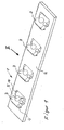
- Eine räumliche Darstellung einer Leuchtdiodenanordnung in vergrößerter Darstellung,
- Figur 2:
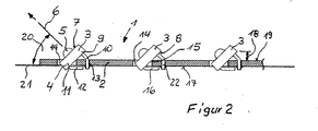
- eine Seitenansicht der Leuchtdiodenanordnung von Figur 1 aus Richtung II im Schnitt,
- Figur 3:
- eine Seitenansicht der Leuchtdiodenanordnung von Figur 1 mit auf die Trägerplatte aufgesteckten Leuchtdioden,
- Figur 4:
- die Leuchtdiodenanordnung von Figur 3 mit gelöteten ersten Paaren von Kontaktbeinchen und
- Figur 5:
- die Leuchtdiodenanordnung von Figur 4 mit abgebogenen Hauptkörpern
- Eine Leuchtdiodenanordnung 1 besteht im wesentlichen aus einer Trägerplatte 2 und einer Mehrzahl von Leuchtdioden 3 bzw. LEDs. Als Leuchtdioden 3 werden beispielsweise sogenannte Piranha-LEDs verwendet. Die Leuchtdioden 3 weisen einen Grundkörper 4 auf, über dessen Lichtaustrittsfläche 5 Licht abgestrahlt wird. Die Abstrahlrichtung 6 ist dabei senkrecht zur Grundkörperoberfläche 7 angeordnet. An seiner der Grundkörperoberfläche 7 abgewandten Unterseite 8 weist der Grundkörper an seinem ersten Ende 9 ein erste Paar von Kontaktbeinchen 10 auf. An seinem dem ersten Ende 9 gegenüberliegenden zweiten Ende 11 weist der Grundkörper 7 an seiner Unterseite 8 ein zweites Paar von Kontaktbeinchen 12 auf.
- Die Trägerplatte 2 ist in bzw. parallel zu eine Grundebene 21 angeordnet. Die Trägerplatte 2 weist nicht dargestellte Leiterbahnen und gegebenenfalls ebenfalls nicht dargestellte elektronische Bauelemente zur Ansteuerung der Leuchtdioden 3 auf. Die Trägerplatte 2 weist für jede Leuchtdiode 3 zwei Führungsbohrungen 13 auf, in denen jeweils das erste Paar von Kontaktbeinchen 10 angeordnet ist. In einem Abstand zu den Führungsbohrungen 13 ist auf der Trägerplatte 2 jeweils ein Durchbruch 14 angeordnet, in den der benachbarte Grundkörper 4 mit seinen zweiten Ende 11 eintaucht. Der Durchbruch 14 weist dabei eine den Führungsbohrungen 13 zugewandte hintere Innenkante 15 auf, gegen die der Grundkörper 4 mit seiner Unterseite 8 anschlägt.
- Das zweite Paar von Kontaktbeinchen 12 liegt mit seinen freien Enden 16 an einer Unterseite 17 der Trägerplatte 2 an.
- Es ist grundsätzlich auch möglich, zwei oder mehrere parallel nebeneinander angeordnete Leuchtdioden 3 in einen gemeinsamen Durchbruch 14 eintauchen zu lassen.
- Die Breite des Durchbruches 14 bzw. die Anordnung der hinteren Innenkante 15 bestimmt zusammen mit dem Abstand 18 von der Trägeroberfläche 19 den von Abstrahlrichtung 6 und Trägeroberfläche 19 gebildeten Neigungswinkel 20.
- An der Unterseite 17 der Trägerplatte 2 kann ein nicht dargestelltes Wärmeableitelement angeordnet sein, über das Wärme von den LEDs 3 abgeleitet werden kann. Während das erste Paar von Kontaktbeinchen 10 zur mechanischen Halterung und zur elektrischen Kontaktierung genutzt wird, wird das zweite Paar von Kontaktbeinchen 12 lediglich zur mechanischen Halterung genutzt.
- Zur Montage der Leuchtdiodenanordnung 1 werden in einem ersten Arbeitsgang die LEDs 3 mit ihrem jeweiligen ersten Paar von Kontaktbeinchen 10 bzw. deren freien Enden 22 in die Führungsbohrungen 13 der Trägerplatte 2 eingesetzt. Das zweite Paar von Kontaktbeinchen 12 ragt dabei mit seinen freien Enden 16 in den benachbarten Durchbruch 14.
- In einem zweiten Arbeitsgang wird das erste Paar von Kontaktbeinchen 12 mit der Trägerplatte 2 bzw. deren Führungsbohrungen 13 verlötet.
- In einem dritten Arbeitsgang werden die Grundkörper 4 so abgebogen, daß ihr zweites Ende in den benachbarten Durchbruch 14 hineinragt und sie mit ihrer der Trägerplatte 2 zugewandten Unterseite 8 an die hintere Innenkante 15 des Durchbruchs 14 anschlagen.
- In einem vierten Arbeitsgang werden die freien Enden 16 des zweiten Paares von Kontaktbeinchen 12 gegen die Unterseite 17 der Trägerplatte 2 gebogen.
Claims (8)
- Leuchtdiodenanordnung, insbesondere für eine Fahrzeugsignalleuchte, mit einer gegenüber einer Grundebene (21) schräg orientierten Abstrahlrichtung (6), bestehend aus einer Trägerplatte (2) und einer Mehrzahl von auf der Trägerplatte angeordneten Leuchtdioden (3), wobei die Trägerplatte (2) parallel zu der Grundebene (21) angeordnet ist und die Leuchtdioden (3) einen Grundkörper (4) aufweisen, der in Abstrahlrichtung (6) geneigt schräg auf der Trägerplatte (2) angeordnet ist, dass der Grundkörper (4) an seinem der Trägerplatte (2) in einem Abstand (18) benachbarten ersten Ende (9) ein erstes Paar von Kontaktbeinchen (10) aufweist, deren freie Enden (22) in Führungsbohrungen (13) der Trägerplatte befestigt sind, und dass der Grundkörper (4) an seinem dem ersten Ende (9) gegenüberliegenden zweiten Ende (11) ein zweites Paar von Kontaktbeinchen (12) aufweist, das den Grundkörper (4) gegenüber der Trägerplatte (2) mechanisch hält, dadurch gekennzeichnet, dass die Trägerplatte (2) einen Durchbruch (14) aufweist, in den der Grundkörper (4) mit seinem zweiten Ende (11) hineinragt.
- Leuchtdiodenanordnung nach Anspruch 1, dadurch gekennzeichnet, dass das zweite Paar von Kontaktbeinchen (12) mit seinen freien Enden (16) an einer Unterseite (17) der Trägerplatte (2) anliegt.
- Leuchtdiodenanordnung nach einem Anspruch 1 oder 2, dadurch gekennzeichnet, dass eine Mehrzahl von parallel zueinander angeordneten Leuchtdioden (3) in den Durchbruch (14) hineinragt.
- Leuchtdiodenanordnung nach einem der Ansprüche 1 bis 3, dadurch gekennzeichnet, dass die Breite des Durchbruchs (14) den Neigungswinkel (20) der Leuchtdiode (3) bestimmt.
- Leuchtdiodenanordnung nach einem der Ansprüche 1 bis 4, dadurch gekennzeichnet, dass die Leuchtdioden (3) in unterschiedliche Abstrahlrichtungen (6) ausgerichtet sind.
- Leuchtdiodenanordnung nach einem der Ansprüche 1 bis 5, dadurch gekennzeichnet, dass die Trägerplatten (2) auf ihrer den Leuchtdioden (3) abgewandten Unterseite (17) ein Wärmeableitelement aufweisen.
- Leuchtdiodenanordnung nach Anspruch 1, dadurch gekennzeichnet, dass der Grundkörper (4) mit seiner der Trägerplatte (2) zugewandten Unterseite (8) gegen eine den Führungsbohrungen (13) zugewandte hintere Innenkante (15) des Durchbruchs (14) anschlägt.
- Verfahren zur schrägen Anordnung von einer Mehrzahl von Leuchtdioden auf einer Trägerplatte, dadurch gekennzeichnet, dass die Leuchtdioden (3) in einem ersten Arbeitsgang mit ihrem an einem ersten Ende (9) eines Grundkörpers (4) angeordneten ersten Paar von Kontaktbeinchen (10) in Führungsbohrungen (13) der Trägerplatte (2) eingesetzt werden, wobei die freien Enden (16) eines an einem dem ersten Ende (9) abgewandten zweiten Ende (11) angeordneten zweiten Kontaktpaares (12) in einen benachbarten Durchbruch (14) hineinragen, dass die Leuchtdioden (3) in einem zweiten Arbeitsgang mit ihrem ersten Paar von Kontaktbeinchen (10) mit der Trägerplatte (2) verlötet werden, dass die Leuchtdioden (3) in einem dritten Arbeitsgang so abgebogen werden, dass die Grundkörper (4) mit ihrem zweiten Ende (11) in die Durchbrüche (14) hineinragen und mit ihrer der Trägerplatte (2) zugewandten Unterseite (8) an eine Innenkante (15) des Durchbruchs (14) anschlagen, und dass in einem vierten Arbeitsgang die freien Enden (16) des zweiten Paares von Kontaktbeinchen (12) gegen die Unterseite (17) der Trägerplatte (2) gebogen werden.
Applications Claiming Priority (2)
| Application Number | Priority Date | Filing Date | Title |
|---|---|---|---|
| DE19933060A DE19933060A1 (de) | 1999-07-15 | 1999-07-15 | Leuchtdiodenanordnung |
| DE19933060 | 1999-07-15 |
Publications (3)
| Publication Number | Publication Date |
|---|---|
| EP1069371A2 EP1069371A2 (de) | 2001-01-17 |
| EP1069371A3 EP1069371A3 (de) | 2002-04-24 |
| EP1069371B1 true EP1069371B1 (de) | 2007-08-29 |
Family
ID=7914814
Family Applications (1)
| Application Number | Title | Priority Date | Filing Date |
|---|---|---|---|
| EP00113959A Expired - Lifetime EP1069371B1 (de) | 1999-07-15 | 2000-07-01 | Leuchtdiodenanordnung |
Country Status (6)
| Country | Link |
|---|---|
| US (1) | US6450663B1 (de) |
| EP (1) | EP1069371B1 (de) |
| AT (1) | ATE371954T1 (de) |
| AU (1) | AU758674B2 (de) |
| DE (2) | DE19933060A1 (de) |
| NZ (1) | NZ505415A (de) |
Families Citing this family (47)
| Publication number | Priority date | Publication date | Assignee | Title |
|---|---|---|---|---|
| US6618123B2 (en) * | 2000-10-20 | 2003-09-09 | Matsushita Electric Industrial Co., Ltd. | Range-finder, three-dimensional measuring method and light source apparatus |
| USD471166S1 (en) | 2001-04-06 | 2003-03-04 | Kabushiki Kaisha Toshiba | Light emitting semiconductor device |
| USD516527S1 (en) | 2001-12-28 | 2006-03-07 | Nichia Corporation | Light emitting diode |
| USD557224S1 (en) | 2001-12-28 | 2007-12-11 | Nichia Corporation | Light emitting diode |
| USD519943S1 (en) | 2001-12-28 | 2006-05-02 | Nichia Corporation | Light emitting diode |
| USD565516S1 (en) | 2001-12-28 | 2008-04-01 | Nichia Corporation | Light emitting diode |
| USD482337S1 (en) | 2001-12-28 | 2003-11-18 | Nichia Corporation | Light emitting diode (LED) |
| USD547736S1 (en) | 2001-12-28 | 2007-07-31 | Nichia Corporation | Light emitting diode |
| USD534505S1 (en) | 2001-12-28 | 2007-01-02 | Nichia Corporation | Light emitting diode |
| USD499384S1 (en) | 2001-12-28 | 2004-12-07 | Nichia Corporation | Light emitting diode |
| USD477580S1 (en) | 2002-01-30 | 2003-07-22 | Nichia Corporation | Light emitting diode |
| USD488137S1 (en) | 2002-01-30 | 2004-04-06 | Nichia Corporation | Light emitting diode |
| JP2003264299A (ja) * | 2002-03-11 | 2003-09-19 | Honda Motor Co Ltd | 受光装置、発光装置及び光無線通信装置 |
| US7380961B2 (en) | 2002-04-24 | 2008-06-03 | Moriyama Sangyo Kabushiki Kaisha | Light source coupler, illuminant device, patterned conductor, and method for manufacturing light source coupler |
| JP2004047256A (ja) * | 2002-07-11 | 2004-02-12 | Honda Motor Co Ltd | 点灯装置 |
| US8911086B2 (en) | 2002-12-06 | 2014-12-16 | Amo Manufacturing Usa, Llc | Compound modulation transfer function for laser surgery and other optical applications |
| DE10303969B4 (de) * | 2003-01-31 | 2008-11-27 | Osram Opto Semiconductors Gmbh | Leuchtdiodenanordnung mit einem Leuchtdiodenträger und einer Mehrzahl von Leuchtdioden |
| JP4245968B2 (ja) * | 2003-04-23 | 2009-04-02 | 株式会社小糸製作所 | 車両用前照灯 |
| US20050001433A1 (en) * | 2003-04-30 | 2005-01-06 | Seelink Technology Corporation | Display system having uniform luminosity and wind generator |
| US7334918B2 (en) * | 2003-05-07 | 2008-02-26 | Bayco Products, Ltd. | LED lighting array for a portable task light |
| JP4664285B2 (ja) * | 2003-06-20 | 2011-04-06 | ヴィズイクス・インコーポレーテッド | 波面測定に基づき客観的視力を予測するためのシステム及び方法 |
| US8596787B2 (en) | 2003-06-20 | 2013-12-03 | Amo Manufacturing Usa, Llc | Systems and methods for prediction of objective visual acuity based on wavefront measurements |
| JP4061251B2 (ja) * | 2003-08-05 | 2008-03-12 | 株式会社小糸製作所 | 車両用灯具 |
| WO2005054745A1 (en) * | 2003-12-05 | 2005-06-16 | Auto Concepts Australia Pty Ltd | A lamp assembly |
| JP4360191B2 (ja) * | 2003-12-05 | 2009-11-11 | 株式会社小糸製作所 | 車両用前照灯 |
| AT500892B1 (de) * | 2004-09-01 | 2008-01-15 | Pollmann Austria Ohg | Lichtquellen-trageinheit |
| DE102004061472A1 (de) * | 2004-12-21 | 2006-07-06 | Carl Freudenberg Kg | Baueinheit mit einem Flachkabel aus einer mehradrigen flexiblen Flachbandleitung |
| DE102005013155A1 (de) * | 2005-03-22 | 2006-09-28 | Rapp, Peter | Einstellbarer Abstrahlwinkel einer LED-Lampe |
| USD563012S1 (en) * | 2005-04-11 | 2008-02-26 | Flos S.P.A. | Pendant lamp |
| US7631985B1 (en) * | 2005-05-02 | 2009-12-15 | Genlyte Thomas Group, Llc | Finite element and multi-distribution LED luminaire |
| US7237936B1 (en) * | 2005-05-27 | 2007-07-03 | Gibson David J | Vehicle light assembly and its associated method of manufacture |
| US7772988B1 (en) * | 2005-05-31 | 2010-08-10 | Innovative Lighting, Inc. | LED light assembly with predetermined distribution pattern and built-in retroreflector |
| CN2854308Y (zh) * | 2005-11-07 | 2007-01-03 | 陈晓锋 | 一种长条形建筑物像素灯 |
| TWI308627B (en) * | 2006-12-05 | 2009-04-11 | Ind Tech Res Inst | Illumination device of flexible lighting angle |
| US8042978B2 (en) * | 2007-01-05 | 2011-10-25 | Hong Kong Applied Science and Technology Research Institute Company Limited | Light emitting assembly with heat dissipation structure |
| ITPD20080068A1 (it) * | 2008-02-26 | 2009-08-27 | Easy Internat S R L | Lampada a led e metodo per la sua progettazione |
| KR101566324B1 (ko) * | 2009-03-24 | 2015-11-06 | 삼성디스플레이 주식회사 | 램프 소켓 및 그를 포함하는 표시 장치 |
| CN102072446A (zh) * | 2009-11-24 | 2011-05-25 | 深圳市安华信科技发展有限公司 | 一种led车辆转向辅助灯 |
| USD640212S1 (en) * | 2010-06-28 | 2011-06-21 | Advanced Optoelectric Technology, Inc. | LED light bar |
| USD644189S1 (en) * | 2010-06-28 | 2011-08-30 | Advanced Optoelectronic Technology, Inc. | LED light bar |
| USD662649S1 (en) * | 2010-07-16 | 2012-06-26 | C.S.A. Photonics Limited | Lighting projector |
| USD642994S1 (en) * | 2010-07-23 | 2011-08-09 | Advanced Optoelectronic Technolgy, Inc. | LED light bar |
| USD642995S1 (en) * | 2010-07-23 | 2011-08-09 | Advanced Optoelectronic Technology, Inc. | LED light bar |
| USD642545S1 (en) * | 2010-07-23 | 2011-08-02 | Advanced Optoelectronic Technology, Inc. | LED light bar |
| USD662650S1 (en) * | 2011-09-30 | 2012-06-26 | C.S.A. Photonics Limited | Floodlight projector |
| DE102012013193B4 (de) * | 2012-07-03 | 2020-10-22 | Kostal Automobil Elektrik Gmbh & Co. Kg | Elektronisches Modul |
| US20170080607A1 (en) * | 2015-09-18 | 2017-03-23 | Richard Sahara | Angled light source with uniform broad area illumination |
Citations (1)
| Publication number | Priority date | Publication date | Assignee | Title |
|---|---|---|---|---|
| JPH05152610A (ja) * | 1991-11-30 | 1993-06-18 | Iwasaki Electric Co Ltd | 発光ダイオード及び発光基板 |
Family Cites Families (10)
| Publication number | Priority date | Publication date | Assignee | Title |
|---|---|---|---|---|
| FR2550411B1 (fr) * | 1983-08-01 | 1986-06-13 | Telemecanique Electrique | Support de voyant lumineux sur circuit imprime |
| US4654629A (en) * | 1985-07-02 | 1987-03-31 | Pulse Electronics, Inc. | Vehicle marker light |
| FR2601486B1 (fr) * | 1986-07-11 | 1989-04-14 | Signal Vision Sa | Procede de fabrication d'une plaque eclairante a diodes electroluminescentes et feu de signalisation obtenu par ce procede |
| US5101326A (en) * | 1990-09-27 | 1992-03-31 | The Grote Manufacturing Co. | Lamp assembly for motor vehicle |
| US5567036A (en) * | 1995-04-05 | 1996-10-22 | Grote Industries, Inc. | Clearance and side marker lamp |
| US5519596A (en) * | 1995-05-16 | 1996-05-21 | Hewlett-Packard Company | Moldable nesting frame for light emitting diode array |
| US5857767A (en) * | 1996-09-23 | 1999-01-12 | Relume Corporation | Thermal management system for L.E.D. arrays |
| DE19646042B4 (de) | 1996-11-08 | 2006-11-16 | Automotive Lighting Reutlingen Gmbh | Fahrzeug-Beleuchtungseinrichtung |
| DE29720060U1 (de) | 1997-11-12 | 1998-01-02 | FER Fahrzeugelektrik GmbH, 99817 Eisenach | Kraftfahrzeugleuchte, insbesondere Signalleuchte |
| DE29905944U1 (de) * | 1999-04-01 | 1999-08-12 | Leonhardy Gmbh, 91244 Reichenschwand | Leuchtdiodeneinheit |
-
1999
- 1999-07-15 DE DE19933060A patent/DE19933060A1/de not_active Withdrawn
-
2000
- 2000-06-22 AU AU42611/00A patent/AU758674B2/en not_active Expired
- 2000-06-26 NZ NZ505415A patent/NZ505415A/xx not_active IP Right Cessation
- 2000-07-01 DE DE50014601T patent/DE50014601D1/de not_active Expired - Lifetime
- 2000-07-01 AT AT00113959T patent/ATE371954T1/de not_active IP Right Cessation
- 2000-07-01 EP EP00113959A patent/EP1069371B1/de not_active Expired - Lifetime
- 2000-07-14 US US09/617,428 patent/US6450663B1/en not_active Expired - Lifetime
Patent Citations (1)
| Publication number | Priority date | Publication date | Assignee | Title |
|---|---|---|---|---|
| JPH05152610A (ja) * | 1991-11-30 | 1993-06-18 | Iwasaki Electric Co Ltd | 発光ダイオード及び発光基板 |
Non-Patent Citations (1)
| Title |
|---|
| PATENT ABSTRACTS OF JAPAN vol. 017, no. 542 (E - 1441) 29 September 1993 (1993-09-29) * |
Also Published As
| Publication number | Publication date |
|---|---|
| AU4261100A (en) | 2001-01-18 |
| DE50014601D1 (de) | 2007-10-11 |
| EP1069371A2 (de) | 2001-01-17 |
| ATE371954T1 (de) | 2007-09-15 |
| NZ505415A (en) | 2002-08-28 |
| AU758674B2 (en) | 2003-03-27 |
| DE19933060A1 (de) | 2001-04-26 |
| US6450663B1 (en) | 2002-09-17 |
| EP1069371A3 (de) | 2002-04-24 |
Similar Documents
| Publication | Publication Date | Title |
|---|---|---|
| EP1069371B1 (de) | Leuchtdiodenanordnung | |
| EP0896898B1 (de) | Träger, vorzugsweise für Heckleuchten von Kraftfahrzeugen | |
| EP2327929A1 (de) | Leuchteinheit für Fahrzeuge und Montageverfahren | |
| EP1099601B1 (de) | Kraftfahrzeugleuchte | |
| EP1046859A1 (de) | Leuchteinrichtung | |
| DE3736833A1 (de) | Elektrische baugruppe mit abschirmvorrichtung | |
| DE102017100165A1 (de) | Lichtemittierende Anordnung und lichtemittierendes System | |
| DE19839118C2 (de) | Konstruktionsanordnung für die Befestigung eines Bauelements auf einer gedruckten Leiterplatte und elektronische Geräte mit dieser Konstruktion | |
| EP0981722B1 (de) | Messwerk | |
| EP1968365B1 (de) | Leiterplatte mit einem winkelförmigen Stanzgitter bestückt | |
| DE10225543A1 (de) | Träger für Leuchtelemente in einer Kraftfahrzeugleuchte | |
| EP0810119B1 (de) | Anzeigeeinrichtung für Kraftfahrzeuge | |
| DE10134562A1 (de) | System und Verfahren zur elektrischen Kontaktierung und mechanischen Befestigung von Leiterplatten | |
| EP0585816A1 (de) | Stecksockel mit angelöteter Leiterplatte | |
| WO2000030892A1 (de) | Leuchte für fahrzeuge | |
| DE3014172C2 (de) | Elektrische Verbindungseinrichtung | |
| DE102020100200A1 (de) | Beleuchtungsvorrichtung und Montageverfahren | |
| EP2982904B1 (de) | Leuchte | |
| DE10020099A1 (de) | Kraftfahrzeugleuchte | |
| EP1406351B1 (de) | Stiftleiste | |
| EP1519145A1 (de) | Anordnung mit einem Sensor | |
| EP1000804A2 (de) | Scheinwerfer für Fahrzeuge und Verfahren zur Montage | |
| DE3436988C2 (de) | Lampenträger für Kraftfahrzeugleuchten | |
| DE29912688U1 (de) | Optische Anzeigeeinrichtung | |
| EP0110218B1 (de) | Signallampe mit Leuchtdiode |
Legal Events
| Date | Code | Title | Description |
|---|---|---|---|
| PUAI | Public reference made under article 153(3) epc to a published international application that has entered the european phase |
Free format text: ORIGINAL CODE: 0009012 |
|
| AK | Designated contracting states |
Kind code of ref document: A2 Designated state(s): AT BE CH CY DE DK ES FI FR GB GR IE IT LI LU MC NL PT SE Kind code of ref document: A2 Designated state(s): AT DE ES FR GB IT |
|
| AX | Request for extension of the european patent |
Free format text: AL;LT;LV;MK;RO;SI |
|
| PUAL | Search report despatched |
Free format text: ORIGINAL CODE: 0009013 |
|
| AK | Designated contracting states |
Kind code of ref document: A3 Designated state(s): AT BE CH CY DE DK ES FI FR GB GR IE IT LI LU MC NL PT SE |
|
| AX | Request for extension of the european patent |
Free format text: AL;LT;LV;MK;RO;SI |
|
| RIC1 | Information provided on ipc code assigned before grant |
Free format text: 7H 01L 25/075 A |
|
| 17P | Request for examination filed |
Effective date: 20021019 |
|
| AKX | Designation fees paid |
Free format text: AT DE ES FR GB IT |
|
| RAP1 | Party data changed (applicant data changed or rights of an application transferred) |
Owner name: HELLA KGAA HUECK & CO. |
|
| GRAP | Despatch of communication of intention to grant a patent |
Free format text: ORIGINAL CODE: EPIDOSNIGR1 |
|
| GRAS | Grant fee paid |
Free format text: ORIGINAL CODE: EPIDOSNIGR3 |
|
| GRAA | (expected) grant |
Free format text: ORIGINAL CODE: 0009210 |
|
| AK | Designated contracting states |
Kind code of ref document: B1 Designated state(s): AT DE ES FR GB IT |
|
| REG | Reference to a national code |
Ref country code: GB Ref legal event code: FG4D Free format text: NOT ENGLISH |
|
| REF | Corresponds to: |
Ref document number: 50014601 Country of ref document: DE Date of ref document: 20071011 Kind code of ref document: P |
|
| PG25 | Lapsed in a contracting state [announced via postgrant information from national office to epo] |
Ref country code: ES Free format text: LAPSE BECAUSE OF FAILURE TO SUBMIT A TRANSLATION OF THE DESCRIPTION OR TO PAY THE FEE WITHIN THE PRESCRIBED TIME-LIMIT Effective date: 20071210 |
|
| GBV | Gb: ep patent (uk) treated as always having been void in accordance with gb section 77(7)/1977 [no translation filed] |
Effective date: 20070829 |
|
| ET | Fr: translation filed | ||
| PG25 | Lapsed in a contracting state [announced via postgrant information from national office to epo] |
Ref country code: GB Free format text: LAPSE BECAUSE OF FAILURE TO SUBMIT A TRANSLATION OF THE DESCRIPTION OR TO PAY THE FEE WITHIN THE PRESCRIBED TIME-LIMIT Effective date: 20070829 |
|
| PLBE | No opposition filed within time limit |
Free format text: ORIGINAL CODE: 0009261 |
|
| STAA | Information on the status of an ep patent application or granted ep patent |
Free format text: STATUS: NO OPPOSITION FILED WITHIN TIME LIMIT |
|
| 26N | No opposition filed |
Effective date: 20080530 |
|
| PG25 | Lapsed in a contracting state [announced via postgrant information from national office to epo] |
Ref country code: AT Free format text: LAPSE BECAUSE OF NON-PAYMENT OF DUE FEES Effective date: 20080701 |
|
| PG25 | Lapsed in a contracting state [announced via postgrant information from national office to epo] |
Ref country code: IT Free format text: LAPSE BECAUSE OF NON-PAYMENT OF DUE FEES Effective date: 20080731 |
|
| PGFP | Annual fee paid to national office [announced via postgrant information from national office to epo] |
Ref country code: FR Payment date: 20130724 Year of fee payment: 14 |
|
| REG | Reference to a national code |
Ref country code: FR Ref legal event code: ST Effective date: 20150331 |
|
| PG25 | Lapsed in a contracting state [announced via postgrant information from national office to epo] |
Ref country code: FR Free format text: LAPSE BECAUSE OF NON-PAYMENT OF DUE FEES Effective date: 20140731 |
|
| REG | Reference to a national code |
Ref country code: DE Ref legal event code: R081 Ref document number: 50014601 Country of ref document: DE Owner name: HELLA GMBH & CO. KGAA, DE Free format text: FORMER OWNER: HELLA KG HUECK & CO., 59557 LIPPSTADT, DE |
|
| PGFP | Annual fee paid to national office [announced via postgrant information from national office to epo] |
Ref country code: DE Payment date: 20190618 Year of fee payment: 20 |