EP1096243B1 - Halbleiterdruckwandler mit Filter - Google Patents
Halbleiterdruckwandler mit Filter Download PDFInfo
- Publication number
- EP1096243B1 EP1096243B1 EP00122976A EP00122976A EP1096243B1 EP 1096243 B1 EP1096243 B1 EP 1096243B1 EP 00122976 A EP00122976 A EP 00122976A EP 00122976 A EP00122976 A EP 00122976A EP 1096243 B1 EP1096243 B1 EP 1096243B1
- Authority
- EP
- European Patent Office
- Prior art keywords
- filter
- cavity
- housing
- physical sensor
- component
- Prior art date
- Legal status (The legal status is an assumption and is not a legal conclusion. Google has not performed a legal analysis and makes no representation as to the accuracy of the status listed.)
- Expired - Lifetime
Links
Images
Classifications
-
- G—PHYSICS
- G01—MEASURING; TESTING
- G01L—MEASURING FORCE, STRESS, TORQUE, WORK, MECHANICAL POWER, MECHANICAL EFFICIENCY, OR FLUID PRESSURE
- G01L19/00—Details of, or accessories for, apparatus for measuring steady or quasi-steady pressure of a fluent medium insofar as such details or accessories are not special to particular types of pressure gauges
- G01L19/0061—Electrical connection means
- G01L19/0069—Electrical connection means from the sensor to its support
-
- G—PHYSICS
- G01—MEASURING; TESTING
- G01L—MEASURING FORCE, STRESS, TORQUE, WORK, MECHANICAL POWER, MECHANICAL EFFICIENCY, OR FLUID PRESSURE
- G01L19/00—Details of, or accessories for, apparatus for measuring steady or quasi-steady pressure of a fluent medium insofar as such details or accessories are not special to particular types of pressure gauges
- G01L19/14—Housings
- G01L19/147—Details about the mounting of the sensor to support or covering means
-
- H—ELECTRICITY
- H01—ELECTRIC ELEMENTS
- H01L—SEMICONDUCTOR DEVICES NOT COVERED BY CLASS H10
- H01L2224/00—Indexing scheme for arrangements for connecting or disconnecting semiconductor or solid-state bodies and methods related thereto as covered by H01L24/00
- H01L2224/01—Means for bonding being attached to, or being formed on, the surface to be connected, e.g. chip-to-package, die-attach, "first-level" interconnects; Manufacturing methods related thereto
- H01L2224/42—Wire connectors; Manufacturing methods related thereto
- H01L2224/47—Structure, shape, material or disposition of the wire connectors after the connecting process
- H01L2224/48—Structure, shape, material or disposition of the wire connectors after the connecting process of an individual wire connector
- H01L2224/481—Disposition
- H01L2224/48151—Connecting between a semiconductor or solid-state body and an item not being a semiconductor or solid-state body, e.g. chip-to-substrate, chip-to-passive
- H01L2224/48221—Connecting between a semiconductor or solid-state body and an item not being a semiconductor or solid-state body, e.g. chip-to-substrate, chip-to-passive the body and the item being stacked
- H01L2224/48245—Connecting between a semiconductor or solid-state body and an item not being a semiconductor or solid-state body, e.g. chip-to-substrate, chip-to-passive the body and the item being stacked the item being metallic
- H01L2224/48247—Connecting between a semiconductor or solid-state body and an item not being a semiconductor or solid-state body, e.g. chip-to-substrate, chip-to-passive the body and the item being stacked the item being metallic connecting the wire to a bond pad of the item
Definitions
- Physical sensor components such as silicon pressure sensors can be used in automotive, industrial, consumer white goods, and various other applications.
- encapsulants have been used to protect the silicon pressure sensor.
- none of these encapsulants are entirely impermeable to corrosive solutions.
- the encapsulants do not completely satisfy the customers' stringent reliability requirements, and the encapsulants also do not enable the silicon pressure sensors to remain fully operative during their expected lifetimes.
- a common failure mechanism for a silicon pressure sensor having a prior art encapsulant involves diffusion of the corrosive media followed by the delamination of the encapsulant from the silicon pressure sensor. This delamination exposes portions of the sensor that subsequently corrode from the direct exposure to the chemical environments.
- Figure 1 in US-A-5,900,554 indicates a semiconductor pressure sensor with gel and filter.
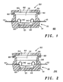
- FIG. 1 illustrates a cross-sectional view of a physical sensor component 100 in accordance with a first embodiment of the present invention.
- Component 100 includes a support structure or housing 110.
- Housing 110 includes a portion 111 that defines a recess or cavity 112 within housing 110.
- Housing 110 should be comprised of a material that is resistant to or that is inert in the environment in which component 100 is to be used.
- portion 111 is comprised of an electrically insulating material such as, for example, a plastic.
- Housing 110 also includes electrical leads 113 that extend from within cavity 112 through the walls of portion 111.
- Component 100 also includes a physical sensor device 120.
- Device 120 is preferably an electro-mechanical device or a transducer such as, for example, a pressure sensor.
- Device 120 includes a physical sensing portion 121.
- portion 121 represents a flexible diaphragm in the pressure sensor.
- Device 120 is located in cavity 112 and is mounted to portion 111 of housing 110.
- an adhesive 130 can be used to physically couple device 120 to portion 111.
- the term "couple” as used herein is defined as directly or indirectly connected in a mechanical, magnetic, electrostatic, or other manner.
- Device 120 is electrically coupled to leads 113.
- wire bonds 140 can be used to provide the electrical coupling.
- Component 100 also includes a lid 150 that covers cavity 112 and housing 110.
- Lid 150 protects device 120 from the environment outside of housing 110 while permitting pressure from the environment to pass through lid 150 and into cavity 112. This pressure within recess 112 is subsequently detected by device 120.
- lid 150 is permanently or fixedly coupled to housing 110.
- lid 150 can be replaced by another lid if lid 150 becomes damaged during the use of component 100.
- Lid 150 is fastened or secured to housing 110 by a mechanism 160, which can be, for example, chemical, mechanical, magnetic, ultrasonic, heat stake or any combination thereof.
- mechanism 160 provides a hermetic seal around the perimeter of housing 110.
- mechanism 160 can be comprised of an adhesive such as, for example, an epoxy.
- Lid 150 includes a port 151 having a hole 152 overlying cavity 112.
- a filter 153 is placed adjacent to hole 152 to form a lid assembly.
- the lid assembly is placed over cavity 112 to seal cavity 112.
- Filter 153 is preferably fixedly coupled to the underside of port 151, which faces towards device 120 and cavity 112.
- filter 153 can be ultrasonically bonded to port 151.
- Lid 150, filter 153, and mechanism 160 should be comprised of materials that are resistant to or that are inert in the environment in which component 100 is to be used.
- Filter 153 is preferably a chemically selective and physically selective filter.
- filter 153 is porous to permit pressure in the environment outside of cavity 112 to move through filter 153 and into cavity 112, and vice versa.
- filter 153 is comprised of a polymer resin comprised of fluorine, such as poly-tetra-fluoro-ethylene.
- filter 153 is preferably chemically treated to be both hydrophobic and oleophobic. With these characteristics, filter 153 is capable of preventing water and oil from entering cavity 112.
- filter 153 can be commercially purchased from Donaldson Europe N.V. in Leuven, Belgium.
- Components in the prior art typically encapsulate a pressure sensitive device with a prior art gel that transmits pressure to provide the protection afforded by filter 153.
- the prior art pressure sensitive encapsulation introduces an offset in the electrical output of the pressure sensitive device.
- the sensor span or sensitivity and temperature coefficients can be altered with the prior art gels. This effect on device output is highly undesirable, especially because it can be difficult to compensate.
- Component 100 solves the problem of the prior art by separating or spacing apart filter 153 and the pressure sensitive portion 121 of device 120 such that filter 153 does not directly contact physical sensing portion 121 of device 120.
- lid 150 provides superior protection from the environment for device 120 compared to the prior art gels, and lid 150 is also more versatile than prior art gels because lid 150 is replaceable while the prior art gels are not replaceable.
- FIG. 2 illustrates a cross-sectional view of a physical sensor component 200, which is similar to component 100 of FIG. 1 in accordance with a second embodiment of the present invention.
- Component 200 in FIG. 2 includes, among other features, a passivation layer 210 in cavity 112.
- Layer 210 is located between filter 153 and device 120.
- Layer 210 covers and provides additional protection for the metallic portions of component 200 against corrosion resulting from the environment outside of cavity 112 that inadvertently pass through filter 153 and into the cavity 112.
- Layer 210 may overlie portion 121 of device 120, but layer 210 can be thinner than the encapsulants used in the prior art because of the additional protection provided by lid 150. In this manner, the prior art problem of the variable offset in the output of the pressure sensitive device is alleviated.
- layer 210 should be a flexible material in order to permit device 120 to sense the pressure through layer 210.
- layer 210 can be comprised of a dimethyl silicone, fluorosilicone, or fluorocarbon gel or a parylene film.
- an improved physical sensor component is provided to overcome the disadvantages of the prior art.
- the component described herein is protected against corrosion by a technique that does not introduce adverse mechanical effects on the performance of the pressure sensing device. Accordingly, the component described herein has fewer limitations as to its use.
Claims (6)
- Physikalische Sensorkomponente, die umfasst:ein Gehäuse (110) mit einem Hohlraum (112);ein Drucksensorhalbleiterbauteil (120), das in dem Hohlraum des Gehäuses befestigt ist; undein Filter (153), das über dem Hohlraum des Gehäuses liegt und von dem Drucksensor getrennt angeordnet ist;dadurch gekennzeichnet, dass:das Gehäuse einen abnehmbaren Deckel (151) hat, der gegenüber einem restlichen Teil des Gehäuses hermetisch abgedichtet ist; unddas Filter (153) durchlässig und chemisch behandelt ist, so dass es sowohl wasser- als auch ölabweisend ist, um zu verhindern, dass weder Wasser noch Öl, das sich außerhalb des Gehäuses befindet, in den Hohlraum eintritt, wobei das Filter des Drucksensorhalbleiterbauteils erlaubt, in dem Hohlraum Druck ohne Verwendung eines Gels in dem Hohlraum zu erfassen.
- Physikalische Sensorkomponente gemäß Anspruch 1, wobei das Filter (153) weiter dadurch gekennzeichnet ist, das es mittels Ultraschall an dem abnehmbaren Deckel befestigt ist.
- Physikalische Sensorkomponente gemäß Anspruch 1, weiterhin dadurch gekennzeichnet, dass das Filter (153) ein polymeres Harz umfasst, das durch Fluor gekennzeichnet ist.
- Physikalische Sensorkomponente gemäß Anspruch 1, weiterhin dadurch gekennzeichnet, dass das Filter (153) durch Entfernen des abnehmbaren Deckels ersetzbar ist.
- Physikalische Sensorkomponente gemäß Anspruch 1, dadurch gekennzeichnet, dass sie als ein Übertragungsmittel in dem Hohlraum ausschließlich Luft verwendet.
- Physikalische Sensorkomponente gemäß Anspruch 1, weiterhin durch eine Passivierungsschicht (210) zwischen dem physikalischen Halbleitersensorbauteil und dem Filter (153) gekennzeichnet.
Applications Claiming Priority (2)
| Application Number | Priority Date | Filing Date | Title |
|---|---|---|---|
| US429099 | 1999-10-28 | ||
| US09/429,099 US6453749B1 (en) | 1999-10-28 | 1999-10-28 | Physical sensor component |
Publications (3)
| Publication Number | Publication Date |
|---|---|
| EP1096243A2 EP1096243A2 (de) | 2001-05-02 |
| EP1096243A3 EP1096243A3 (de) | 2002-06-12 |
| EP1096243B1 true EP1096243B1 (de) | 2005-09-21 |
Family
ID=23701802
Family Applications (1)
| Application Number | Title | Priority Date | Filing Date |
|---|---|---|---|
| EP00122976A Expired - Lifetime EP1096243B1 (de) | 1999-10-28 | 2000-10-23 | Halbleiterdruckwandler mit Filter |
Country Status (4)
| Country | Link |
|---|---|
| US (1) | US6453749B1 (de) |
| EP (1) | EP1096243B1 (de) |
| JP (1) | JP2001165799A (de) |
| DE (1) | DE60022719T2 (de) |
Families Citing this family (33)
| Publication number | Priority date | Publication date | Assignee | Title |
|---|---|---|---|---|
| DE10117296A1 (de) * | 2001-04-06 | 2002-10-17 | Krupp Uhde Gmbh | Druckaufnehmer insbesondere für Wirbelschichtreaktoren |
| US6769319B2 (en) * | 2001-07-09 | 2004-08-03 | Freescale Semiconductor, Inc. | Component having a filter |
| US6787897B2 (en) * | 2001-12-20 | 2004-09-07 | Agilent Technologies, Inc. | Wafer-level package with silicon gasket |
| JP2005524134A (ja) * | 2002-04-25 | 2005-08-11 | グラクソ グループ リミテッド | 環境条件を検知するための磁気音響センサーシステムおよびそれに関連する方法 |
| US7078796B2 (en) * | 2003-07-01 | 2006-07-18 | Freescale Semiconductor, Inc. | Corrosion-resistant copper bond pad and integrated device |
| US20050001316A1 (en) * | 2003-07-01 | 2005-01-06 | Motorola, Inc. | Corrosion-resistant bond pad and integrated device |
| JP2006234481A (ja) * | 2005-02-23 | 2006-09-07 | Bridgestone Corp | センサモジュール及びセンサモジュールを備えた空気入りタイヤ |
| US7231829B2 (en) * | 2005-03-31 | 2007-06-19 | Medtronic, Inc. | Monolithic integrated circuit/pressure sensor on pacing lead |
| DE102005015643A1 (de) | 2005-04-05 | 2006-11-02 | Huf Hülsbeck & Fürst Gmbh & Co. Kg | Betätigungsvorrichtung |
| JP2007064837A (ja) * | 2005-08-31 | 2007-03-15 | Denso Corp | 圧力センサ |
| JP2007114001A (ja) * | 2005-10-19 | 2007-05-10 | Denso Corp | 圧力センサ |
| US7528468B2 (en) * | 2006-09-25 | 2009-05-05 | Freescale Semiconductor, Inc. | Capacitor assembly with shielded connections and method for forming the same |
| US8215835B2 (en) | 2007-12-11 | 2012-07-10 | Tokitae Llc | Temperature-stabilized medicinal storage systems |
| US20090145912A1 (en) * | 2007-12-11 | 2009-06-11 | Searete Llc, A Limited Liability Corporation Of The State Of Delaware | Temperature-stabilized storage containers |
| US9205969B2 (en) * | 2007-12-11 | 2015-12-08 | Tokitae Llc | Temperature-stabilized storage systems |
| US8215518B2 (en) * | 2007-12-11 | 2012-07-10 | Tokitae Llc | Temperature-stabilized storage containers with directed access |
| US9139351B2 (en) * | 2007-12-11 | 2015-09-22 | Tokitae Llc | Temperature-stabilized storage systems with flexible connectors |
| US8069680B2 (en) | 2007-12-11 | 2011-12-06 | Tokitae Llc | Methods of manufacturing temperature-stabilized storage containers |
| US8887944B2 (en) | 2007-12-11 | 2014-11-18 | Tokitae Llc | Temperature-stabilized storage systems configured for storage and stabilization of modular units |
| US8377030B2 (en) * | 2007-12-11 | 2013-02-19 | Tokitae Llc | Temperature-stabilized storage containers for medicinals |
| US9140476B2 (en) | 2007-12-11 | 2015-09-22 | Tokitae Llc | Temperature-controlled storage systems |
| US9174791B2 (en) * | 2007-12-11 | 2015-11-03 | Tokitae Llc | Temperature-stabilized storage systems |
| US7591185B1 (en) * | 2008-04-23 | 2009-09-22 | Medtronic, Inc. | Pressure sensor configurations for implantable medical electrical leads |
| JP4737727B2 (ja) * | 2009-06-26 | 2011-08-03 | 横浜ゴム株式会社 | タイヤ状態取得装置及びタイヤ状態監視システム |
| US9372016B2 (en) | 2013-05-31 | 2016-06-21 | Tokitae Llc | Temperature-stabilized storage systems with regulated cooling |
| US9447995B2 (en) | 2010-02-08 | 2016-09-20 | Tokitac LLC | Temperature-stabilized storage systems with integral regulated cooling |
| US9625333B2 (en) | 2013-03-15 | 2017-04-18 | President And Fellows Of Harvard College | Tactile sensor |
| US20150090030A1 (en) * | 2013-09-27 | 2015-04-02 | Infineon Technologies Ag | Transducer arrangement comprising a transducer die and method of covering a transducer die |
| US10053269B2 (en) * | 2015-02-09 | 2018-08-21 | The Boeing Company | Multi-functional fiber optic fuel sensor system having a photonic membrane |
| US9799580B2 (en) * | 2016-03-24 | 2017-10-24 | Nxp Usa, Inc. | Semiconductor device package and methods of manufacture thereof |
| CN107290096A (zh) * | 2016-04-11 | 2017-10-24 | 飞思卡尔半导体公司 | 具有膜片的压力感测集成电路器件 |
| US11837513B2 (en) * | 2019-07-17 | 2023-12-05 | Texas Instruments Incorporated | O-ring seals for fluid sensing |
| US11408788B2 (en) * | 2020-03-31 | 2022-08-09 | Toyota Research Institute, Inc. | Variable geometry and stiffness control for fluid filled sensor |
Family Cites Families (31)
| Publication number | Priority date | Publication date | Assignee | Title |
|---|---|---|---|---|
| US3574284A (en) * | 1967-06-26 | 1971-04-13 | Laucks Lab Inc | Pore pressure apparatus and method |
| US3619742A (en) * | 1970-05-21 | 1971-11-09 | Rosemount Eng Co Ltd | Shielded capacitance pressure sensor |
| US4034609A (en) * | 1976-01-02 | 1977-07-12 | Fuller David L | Digital sensing device |
| US4177496A (en) * | 1976-03-12 | 1979-12-04 | Kavlico Corporation | Capacitive pressure transducer |
| JPS59224534A (ja) * | 1983-06-03 | 1984-12-17 | Citizen Watch Co Ltd | 圧力電気変換器 |
| US4571244A (en) * | 1984-05-07 | 1986-02-18 | Biogenesis, Inc. | System for removing gas bubbles from liquids |
| JPS62194431A (ja) * | 1986-02-21 | 1987-08-26 | Citizen Watch Co Ltd | 圧力センサユニツト |
| US4686764A (en) * | 1986-04-22 | 1987-08-18 | Motorola, Inc. | Membrane protected pressure sensor |
| JPS62184447U (de) * | 1986-05-15 | 1987-11-24 | ||
| JPS6397833U (de) * | 1986-12-15 | 1988-06-24 | ||
| JPS6418036A (en) * | 1987-07-14 | 1989-01-20 | Mitsubishi Electric Corp | Pressure sensor |
| US4909070A (en) * | 1987-10-12 | 1990-03-20 | Smith Jeffery B | Moisture sensor |
| DE68918584T2 (de) | 1988-03-03 | 1995-01-26 | Foxboro Co | Geschützter drucksensor. |
| US4993265A (en) * | 1988-03-03 | 1991-02-19 | The Foxboro Company | Protected pressure sensor and method of making |
| FR2686692B1 (fr) | 1992-01-28 | 1996-08-23 | Jaeger | Capteur de pression a base de semi-conducteur et procede de fabrication. |
| US5308939A (en) * | 1992-07-21 | 1994-05-03 | Fuji Koki Manufacturing Co., Ltd. | Pressure equalizing mechanism for a pressure switch |
| JPH06132545A (ja) * | 1992-10-19 | 1994-05-13 | Mitsubishi Electric Corp | 圧力検出装置 |
| JP3114403B2 (ja) * | 1992-12-22 | 2000-12-04 | 富士電機株式会社 | 半導体圧力センサ |
| JPH07120340A (ja) | 1993-10-22 | 1995-05-12 | Honda Motor Co Ltd | 圧力センサ |
| DE4413274A1 (de) | 1994-04-16 | 1995-10-19 | Sel Alcatel Ag | Drucksensor |
| KR970705015A (ko) | 1994-07-21 | 1997-09-06 | 로더리히 네테부쉬;롤프 옴케 | 실리콘 압력 감지기용 보호 격막 |
| SE9402720D0 (sv) * | 1994-08-15 | 1994-08-15 | Gambro Ab | Insats för tryckgivare |
| JPH08178778A (ja) * | 1994-12-27 | 1996-07-12 | Mitsubishi Electric Corp | 半導体圧力検出装置 |
| US5889211A (en) | 1995-04-03 | 1999-03-30 | Motorola, Inc. | Media compatible microsensor structure and methods of manufacturing and using the same |
| US5747694A (en) | 1995-07-28 | 1998-05-05 | Nippondenso Co., Ltd. | Pressure sensor with barrier in a pressure chamber |
| US5600071A (en) | 1995-09-05 | 1997-02-04 | Motorola, Inc. | Vertically integrated sensor structure and method |
| DE19626083C2 (de) * | 1996-06-28 | 2000-03-23 | Siemens Ag | Sensor-Bauelement |
| DE19626084C2 (de) * | 1996-06-28 | 2003-04-17 | Infineon Technologies Ag | Drucksensorvorrichtung für eine Montage auf der Bestückungsoberfläche einer Leiterplatte |
| DE19626086A1 (de) * | 1996-06-28 | 1998-01-02 | Siemens Ag | Auf der Bestückungsoberfläche einer Leiterplatte montierbares Drucksensor-Bauelement |
| JPH112580A (ja) * | 1997-06-13 | 1999-01-06 | Matsushita Electric Works Ltd | 半導体圧力センサ |
| US6191359B1 (en) * | 1998-10-13 | 2001-02-20 | Intel Corporation | Mass reflowable windowed package |
-
1999
- 1999-10-28 US US09/429,099 patent/US6453749B1/en not_active Expired - Lifetime
-
2000
- 2000-10-23 EP EP00122976A patent/EP1096243B1/de not_active Expired - Lifetime
- 2000-10-23 DE DE60022719T patent/DE60022719T2/de not_active Expired - Fee Related
- 2000-10-27 JP JP2000328153A patent/JP2001165799A/ja active Pending
Also Published As
| Publication number | Publication date |
|---|---|
| DE60022719T2 (de) | 2006-04-27 |
| EP1096243A2 (de) | 2001-05-02 |
| DE60022719D1 (de) | 2006-02-02 |
| US6453749B1 (en) | 2002-09-24 |
| JP2001165799A (ja) | 2001-06-22 |
| US20020050170A1 (en) | 2002-05-02 |
| EP1096243A3 (de) | 2002-06-12 |
Similar Documents
| Publication | Publication Date | Title |
|---|---|---|
| EP1096243B1 (de) | Halbleiterdruckwandler mit Filter | |
| US11192777B2 (en) | MEMS sensor package systems and methods | |
| US7436037B2 (en) | Moisture resistant pressure sensors | |
| US6805010B2 (en) | Pressure sensor module | |
| EP0676628B1 (de) | Spannungsisolierter Halbleiter-Druckwandler | |
| US4295117A (en) | Pressure sensor assembly | |
| US6148673A (en) | Differential pressure sensor and method thereof | |
| JP4165360B2 (ja) | 力学量センサ | |
| US4942383A (en) | Low cost wet-to-wet pressure sensor package | |
| JPH06132545A (ja) | 圧力検出装置 | |
| JP2007218858A (ja) | 半導体圧力センサ装置 | |
| JP2007513349A (ja) | 絶縁圧力変換器 | |
| US11348880B2 (en) | Semiconductor device and electronic apparatus | |
| US6186008B1 (en) | Semiconductor sensor component | |
| JP6480969B2 (ja) | 圧力センサ | |
| JPH05145085A (ja) | 半導体圧力センサ | |
| JP2010281569A (ja) | 圧力センサ用パッケージ | |
| JP3089853B2 (ja) | 半導体感圧素子 | |
| US11085846B2 (en) | Micromechanical sensor device with integrated housing seal, micromechanical sensor assembly, and corresponding manufacturing method | |
| KR20070112455A (ko) | 열 감지기 | |
| JP4224224B2 (ja) | 変換器のケース構造 | |
| JP3620184B2 (ja) | 圧力センサ | |
| JPH11241970A (ja) | 圧力センサ | |
| JP2002188975A (ja) | 圧力センサモジュール | |
| CN112897452B (zh) | 传感器芯片、传感器和电子设备 |
Legal Events
| Date | Code | Title | Description |
|---|---|---|---|
| PUAI | Public reference made under article 153(3) epc to a published international application that has entered the european phase |
Free format text: ORIGINAL CODE: 0009012 |
|
| AK | Designated contracting states |
Kind code of ref document: A2 Designated state(s): AT BE CH CY DE DK ES FI FR GB GR IE IT LI LU MC NL PT SE |
|
| AX | Request for extension of the european patent |
Free format text: AL;LT;LV;MK;RO;SI |
|
| PUAL | Search report despatched |
Free format text: ORIGINAL CODE: 0009013 |
|
| AK | Designated contracting states |
Kind code of ref document: A3 Designated state(s): AT BE CH CY DE DK ES FI FR GB GR IE IT LI LU MC NL PT SE |
|
| AX | Request for extension of the european patent |
Free format text: AL;LT;LV;MK;RO;SI |
|
| 17P | Request for examination filed |
Effective date: 20021212 |
|
| AKX | Designation fees paid |
Designated state(s): DE FR GB |
|
| 17Q | First examination report despatched |
Effective date: 20040906 |
|
| RAP1 | Party data changed (applicant data changed or rights of an application transferred) |
Owner name: FREESCALE SEMICONDUCTOR, INC. |
|
| GRAP | Despatch of communication of intention to grant a patent |
Free format text: ORIGINAL CODE: EPIDOSNIGR1 |
|
| RTI1 | Title (correction) |
Free format text: SEMICONDUCTIVE PRESSURE SENSOR WITH FILTER |
|
| GRAS | Grant fee paid |
Free format text: ORIGINAL CODE: EPIDOSNIGR3 |
|
| GRAA | (expected) grant |
Free format text: ORIGINAL CODE: 0009210 |
|
| AK | Designated contracting states |
Kind code of ref document: B1 Designated state(s): DE FR GB |
|
| REG | Reference to a national code |
Ref country code: GB Ref legal event code: FG4D |
|
| REF | Corresponds to: |
Ref document number: 60022719 Country of ref document: DE Date of ref document: 20051027 Kind code of ref document: P |
|
| REF | Corresponds to: |
Ref document number: 60022719 Country of ref document: DE Date of ref document: 20060202 Kind code of ref document: P |
|
| ET | Fr: translation filed | ||
| PLBE | No opposition filed within time limit |
Free format text: ORIGINAL CODE: 0009261 |
|
| STAA | Information on the status of an ep patent application or granted ep patent |
Free format text: STATUS: NO OPPOSITION FILED WITHIN TIME LIMIT |
|
| 26N | No opposition filed |
Effective date: 20060622 |
|
| PGFP | Annual fee paid to national office [announced via postgrant information from national office to epo] |
Ref country code: GB Payment date: 20060915 Year of fee payment: 7 |
|
| PGFP | Annual fee paid to national office [announced via postgrant information from national office to epo] |
Ref country code: DE Payment date: 20061031 Year of fee payment: 7 |
|
| GBPC | Gb: european patent ceased through non-payment of renewal fee |
Effective date: 20071023 |
|
| PG25 | Lapsed in a contracting state [announced via postgrant information from national office to epo] |
Ref country code: DE Free format text: LAPSE BECAUSE OF NON-PAYMENT OF DUE FEES Effective date: 20080501 |
|
| REG | Reference to a national code |
Ref country code: FR Ref legal event code: ST Effective date: 20080630 |
|
| PGFP | Annual fee paid to national office [announced via postgrant information from national office to epo] |
Ref country code: FR Payment date: 20061003 Year of fee payment: 7 |
|
| PG25 | Lapsed in a contracting state [announced via postgrant information from national office to epo] |
Ref country code: GB Free format text: LAPSE BECAUSE OF NON-PAYMENT OF DUE FEES Effective date: 20071023 |
|
| PG25 | Lapsed in a contracting state [announced via postgrant information from national office to epo] |
Ref country code: FR Free format text: LAPSE BECAUSE OF NON-PAYMENT OF DUE FEES Effective date: 20071031 |