EP1094970B1 - Verfahren zum anbringen eines schulterstücks an einem beutel - Google Patents
Verfahren zum anbringen eines schulterstücks an einem beutel Download PDFInfo
- Publication number
- EP1094970B1 EP1094970B1 EP99926220A EP99926220A EP1094970B1 EP 1094970 B1 EP1094970 B1 EP 1094970B1 EP 99926220 A EP99926220 A EP 99926220A EP 99926220 A EP99926220 A EP 99926220A EP 1094970 B1 EP1094970 B1 EP 1094970B1
- Authority
- EP
- European Patent Office
- Prior art keywords
- hole
- fold line
- shoulder piece
- accordance
- Prior art date
- Legal status (The legal status is an assumption and is not a legal conclusion. Google has not performed a legal analysis and makes no representation as to the accuracy of the status listed.)
- Expired - Lifetime
Links
- 238000000034 method Methods 0.000 title claims description 11
- 239000000463 material Substances 0.000 claims abstract description 33
- 239000011888 foil Substances 0.000 claims description 12
- 238000005520 cutting process Methods 0.000 claims description 4
- 238000004519 manufacturing process Methods 0.000 claims description 2
- 238000000465 moulding Methods 0.000 abstract description 9
- 238000007493 shaping process Methods 0.000 abstract 2
- 230000008878 coupling Effects 0.000 description 19
- 238000010168 coupling process Methods 0.000 description 19
- 238000005859 coupling reaction Methods 0.000 description 19
- 238000003466 welding Methods 0.000 description 6
- 238000007789 sealing Methods 0.000 description 4
- 230000006835 compression Effects 0.000 description 2
- 238000007906 compression Methods 0.000 description 2
- 238000001816 cooling Methods 0.000 description 2
- 239000002985 plastic film Substances 0.000 description 2
- 229920006255 plastic film Polymers 0.000 description 2
- 238000004080 punching Methods 0.000 description 2
- 238000004026 adhesive bonding Methods 0.000 description 1
- 230000000295 complement effect Effects 0.000 description 1
- 239000007789 gas Substances 0.000 description 1
- 239000004816 latex Substances 0.000 description 1
- 229920000126 latex Polymers 0.000 description 1
- 239000004033 plastic Substances 0.000 description 1
- 239000000565 sealant Substances 0.000 description 1
- 238000002604 ultrasonography Methods 0.000 description 1
Images



Classifications
-
- B—PERFORMING OPERATIONS; TRANSPORTING
- B65—CONVEYING; PACKING; STORING; HANDLING THIN OR FILAMENTARY MATERIAL
- B65B—MACHINES, APPARATUS OR DEVICES FOR, OR METHODS OF, PACKAGING ARTICLES OR MATERIALS; UNPACKING
- B65B61/00—Auxiliary devices, not otherwise provided for, for operating on sheets, blanks, webs, binding material, containers or packages
- B65B61/18—Auxiliary devices, not otherwise provided for, for operating on sheets, blanks, webs, binding material, containers or packages for making package-opening or unpacking elements
- B65B61/186—Auxiliary devices, not otherwise provided for, for operating on sheets, blanks, webs, binding material, containers or packages for making package-opening or unpacking elements by applying or incorporating rigid fittings, e.g. discharge spouts
-
- Y—GENERAL TAGGING OF NEW TECHNOLOGICAL DEVELOPMENTS; GENERAL TAGGING OF CROSS-SECTIONAL TECHNOLOGIES SPANNING OVER SEVERAL SECTIONS OF THE IPC; TECHNICAL SUBJECTS COVERED BY FORMER USPC CROSS-REFERENCE ART COLLECTIONS [XRACs] AND DIGESTS
- Y10—TECHNICAL SUBJECTS COVERED BY FORMER USPC
- Y10T—TECHNICAL SUBJECTS COVERED BY FORMER US CLASSIFICATION
- Y10T156/00—Adhesive bonding and miscellaneous chemical manufacture
- Y10T156/12—Surface bonding means and/or assembly means with cutting, punching, piercing, severing or tearing
- Y10T156/1304—Means making hole or aperture in part to be laminated
- Y10T156/1309—Means making hole or aperture in part to be laminated and securing separate part over hole or aperture
Definitions
- the known pouch tubes have a film material made of plastic, which has an end wall and two side walls the tube forms, the side walls along two Side margin sections welded together (or otherwise connected) and a shoulder piece that one lockable outlet nozzle and one on the front wall attached, preferably curved like the end wall Has flange.
- the invention relates to a method for manufacturing of pouch tubes, with a sheet of film material around a fold line running in its longitudinal direction is folded, the superimposed sections of the web extending longitudinally at intervals from one another transversely to the fold line Strips can be joined together to form a Set of bags to form in each bag in the area Fold line a hole is cut, then in each pocket a shoulder piece is inserted that has a closable Outlet connector and one emanating from the connector Has flange, the outlet port of the shoulder piece is inserted through the hole, the flange of the shoulder piece is connected to the film material, the outlet nozzle the shoulder piece is closed, the bag then filled from the open end and finally the open end is closed.
- the object of the invention is this Avoiding difficulties, i.e. precise cutting the hole and warp the film material to avoid.
- the object is achieved by that to cut the hole in each pocket the foil material the pocket in the area of the fold line between two Molded parts are molded and clamped and then in one of the molded parts a knife moved and a counter knife is moved on the other molding.
- the moldings used can be useful be curved, for example, to the connection plane of the two stripes perpendicular axis defining the pocket.
- the flange of the one to be used can also be used in the same way Shoulder piece be curved.
- the pocket can be relatively long in the axial direction his. So that the two molded parts, one of which is in the Bag must be inserted, nevertheless work together precisely can, the knife and the other molding expediently a centering pin and a locating hole for the same.
- FIG. 1 shows a web 1 made of plastic film material, which are continuously handled by a roll 2 and around a fold line running in its longitudinal center line 3 is folded. The path is gradually heading towards of the arrow P moves.
- Welding jaws 4 moved towards the folded film web 5, around the two superimposed sections of the Foil web each along a transverse to the fold line 3 Strip together.
- the one after the other formed connecting strips 6 have in the direction of movement the web 5 distances from each other, so that Foil material between two adjacent ones Strip 6 forms a pocket 7. So there is one Row of pockets 7.
- Cooling elements 8 act at a next station on the connecting strips 6 to do this by the welding process to cool heated foil material.
- the pockets 7 separated from each other by the strips 6 approximately in the middle be cut. This way, individual pockets can be created. But it is also possible to have groups of two or to form more pockets 7. The pockets 7 of each group can then, if desired, in the subsequent stations are each processed together when the tools in these subsequent stations two or more times available. 2 is one by cutting formed single pocket 7 shown.
- the shoulder piece 11 has a threaded, with a screw cap (not shown here) closable Outlet connector 12 and an outlet connector 12, curved in one direction (after a cylindrical surface) Flange 13.
- the molded parts 15 and 16 are 5 and 6 shown on a larger scale.
- the first molded part 15 has a sleeve 17, whose working end 18 is the same as the flange 13 of the shoulder piece 11 of Fig. 3 is curved.
- the axis of curvature (not shown) runs in Figs. 5 and 6 in the Plane.
- the sleeve 17 is axial on a rod 19 slidably guided.
- the rod 19 carries at one end a circular knife 20.
- the rod 19 carries in the preferred embodiment shown one the knife 20 protruding centering pin 21.
- a compression spring 22 Between the end of the sleeve opposite the working end 18 17 and a paragraph on the rod 19 is a compression spring 22 arranged.
- the second molded part 16 has a block 23 a circular opening 24, the edge 25 of which is a counter knife for the knife 20 forms.
- An the opening 24 surrounding surface portion 26 of block 23 the same as the working end 18 of the sleeve 17 curved.
- the first molded part 15 is connected to FIG. 4 described inserted into the open end of a pocket 7
- the centering pin 21 of the first molded part 15 passes through through the pre-hole in the third station in FIG. 1 through the punching tools 9 in the film material of the pocket 7 has been formed.
- the diameter (or generally the Transverse dimension) of the pre-hole is preferably somewhat larger than the diameter of the centering pin 21. If none such a pre-hole is made, a tapered Centering pin 21 are used, the film material can just penetrate.
- the second molding 16 becomes the first molding 15 opposite, to the film material of the pocket 7 created.
- the centering pin 21 of the first Molding 15 in a receiving bore 27 in the second molding 16 added, whereby the two molded parts 15 and 16 are precisely aligned with each other.
- the sleeve 17 and / or the block 23 can do this be heated if desired.
- the front wall of the bag 7 thus receives the same curvature as the flange 13 of the Shoulder piece of FIG. 3.
- Knife 20 By further moving the rod 19 to the block 23 then, under compression of the spring 22, the Knife 20 moved to the counter knife 25 on block 23 and that molded and clamped foil material of the front wall cut the pocket 7.
- the cut out foil ring can through a suction hole 28 in the second molded part 16 are suctioned off.
- a shoulder piece 11 In the pocket 7 with the precisely cut Hole in the front wall is then in a first station 7 with a tool 29 a shoulder piece 11 introduced.
- the front wall of the bag is one Counter tool 30 supports.
- the outlet connector 12 (Fig. 3) the shoulder piece 11 passes through the hole in the End wall of the pocket 7 through.
- the flange 13 (Fig. 3) the shoulder piece 11 is on the front wall of the pocket 7th attached, for example glued or welded.
- the two tools 29 and 30 can simultaneously as Welding heads for welding the flange 13 to the End wall of pocket 7, for example with ultrasound, be trained.
- the cap 32 is screwed on the tool 31 is at the same time an anti-rotation device to prevent the shoulder piece from rotating and the end wall of the pocket 7 is formed.
- the invention has the outlet nozzle 1 (Fig. 3) an external thread, on which the closure cap 32 (Fig. 7) is screwed on to the outlet port 12 closure.
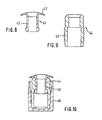
- a shoulder piece 41 can also be used 8 are used.
- This has one Outlet port 42 and one extending from the outlet port Flange 43.
- the outlet port 42 has locking means on to hold a coupling sleeve 44 (Fig. 9), the can be bounced on the outlet port 42 and the in turn has an external thread 45.
- 10 is the coupling sleeve 44 bounced onto the outlet port and shown with a screwed cap 46. Unscrewing (or also bouncing) the cap 46 on the coupling sleeve 44 can before or after the coupling sleeve has been pushed onto the outlet connector 42 take place.
- a shoulder piece with coupling sleeve based on The type described in FIGS. 8 to 10 can also be used in variants be designed so that the edge of the hole in the end wall the pocket 7 through which the shoulder piece is inserted between the flange of the shoulder piece and the coupling sleeve can be clamped.
- Two such Variants are shown in FIGS. 11 and 12 on a larger scale shown.
- Fig. 11 shows how an edge of the film material a pocket 7 between a flange 53 of a shoulder piece 51 and the end of a coupling sleeve 54 clamped is.
- the coupling sleeve 54 is as shown in FIG. 8 to 10 described on an outlet port 52 of the Shoulder piece 51 bounced. Thanks to the clamping of the Foil material can be the welding or gluing of the Foil material with the flange 53 is eliminated.
- the flange can expediently have circular ribs 57 have, which the film material in corresponding Press grooves in the end face of the coupling sleeve.
- FIG. 12 shows a shoulder piece similar to FIG. 11 61 with a flange 63 and a coupling sleeve 64, the edge of the film material of a pocket 7 between the flange 63 and the end face of the coupling sleeve 64 is clamped.
- a suitable sealing medium 68 is arranged in the film material, z. B a latex.
- the end face of the Coupling sleeve 64 suitably circular ribs 69 which have the film material in layer 68 of Press the sealing medium.
- the layer of sealing medium 68 could be a sealant layer also between the film material and the End surface of the coupling sleeve 64 may be arranged.
- a sealing medium layer can be prevented from Gases or vapors from the contents of the bag tube between the outlet piece of the shoulder piece and the coupling sleeve to the film material and then between this and the Get the end face of the coupling sleeve outwards.
Landscapes
- Engineering & Computer Science (AREA)
- Mechanical Engineering (AREA)
- Making Paper Articles (AREA)
- Auxiliary Devices For And Details Of Packaging Control (AREA)
- Packages (AREA)
- Control And Other Processes For Unpacking Of Materials (AREA)
- Containers And Plastic Fillers For Packaging (AREA)
- Air Bags (AREA)
Description
Claims (7)
- Verfahren zur Herstellung von Beuteltuben, wobei eine Bahn (1) aus Folienmaterial um eine in ihrer Längsrichtung verlaufende Faltlinie (3) gefaltet wird, die aufeinandergelegten Abschnitte der Bahn (5) längs in Abständen voneinander quer zur Faltlinie (3) verlaufenden Streifen (6) miteinander verbunden werden, um eine Reihe von Taschen (7) zu bilden, in jede Tasche (7) im Bereich der Faltlinie (3) ein Loch geschnitten wird, dann in jede Tasche (7) ein Schulterstück (11; 41; 51; 61) eingeführt wird, das einen verschliessbaren Auslassstutzen (12; 42; 52) und einen von dem Stutzen ausgehenden Flansch (13; 43; 53; 63) aufweist, der Auslassstutzen (12; 42; 52) des Schulterstücks durch das Loch gesteckt wird, der Flansch (13; 43; 53; 63) des Schulterstücks mit dem Folienmaterial verbunden wird, der Auslassstutzen (12; 42; 52) des Schulterstücks (11; 41; 51; 61) verschlossen wird, die Tasche (7) dann vom offenen Ende her gefüllt wird und schliesslich das offene Ende verschlossen wird, dadurch gekennzeichnet, dass zum Schneiden des Lochs in jede Tasche (7) das Folienmaterial der Tasche im Bereich der Faltlinie (3) zwischen zwei Formteilen (15, 16) geformt und festgeklemmt wird und dann in einem der Formteile (15) ein Messer (20) verschoben und zu einem Gegenmesser (25) am anderen Formteil (16) bewegt wird.
- Verfahren nach Anspruch 1, dadurch gekennzeichnet, dass die verwendeten Formteile (15, 16) gekrümmt sind, im wesentlichen um eine zur Verbindungsebene der beiden die Tasche (7) begrenzenden Streifen (6) senkrechte Achse.
- Verfahren nach Anspruch 1 oder 2, dadurch gekennzeichnet, dass das Messer (20) und das andere Formteil (16) einen Zentrierzapfen (21) und eine Aufnahmebohrung (27) für denselben aufweisen.
- Verfahren nach Anspruch 3, dadurch gekennzeichnet, dass in die Faltlinie (3) der aufeinandergelegten Abschnitte der Bahn (5) ein Ausschnitt (10) gestanzt wird, um ein Vorloch für den nachherigen Durchtritt des Zentrierzapfens (21) zu bilden.
- Verfahren nach Anspruch 4, dadurch gekennzeichnet, dass der grösste Durchmesser des Vorlochs etwas grösser ist als der Durchmesser des Zentrierzapfens (21).
- Verfahren nach einem der Ansprüche 1 bis 5, dadurch gekennzeichnet, dass wenigstens eines der Formteile (15, 16) beheizt wird.
- Verfahren nach einem der Ansprüche 1 bis 6, dadurch gekennzeichnet, dass das ausgeschnittene Folienmaterial durch eine Absaugbohrung (28) in einem der Formteile (16) abgesaugt wird.
Priority Applications (1)
| Application Number | Priority Date | Filing Date | Title |
|---|---|---|---|
| EP99926220A EP1094970B1 (de) | 1998-07-09 | 1999-07-02 | Verfahren zum anbringen eines schulterstücks an einem beutel |
Applications Claiming Priority (4)
| Application Number | Priority Date | Filing Date | Title |
|---|---|---|---|
| EP98810653A EP0970890A1 (de) | 1998-07-09 | 1998-07-09 | Verfahren zum Anbringen eines Schulterstücks an einen Beutel |
| EP98810653 | 1998-07-09 | ||
| PCT/CH1999/000290 WO2000002779A1 (de) | 1998-07-09 | 1999-07-02 | Verfahren zum anbringen eines schulterstücks an einem beutel |
| EP99926220A EP1094970B1 (de) | 1998-07-09 | 1999-07-02 | Verfahren zum anbringen eines schulterstücks an einem beutel |
Publications (2)
| Publication Number | Publication Date |
|---|---|
| EP1094970A1 EP1094970A1 (de) | 2001-05-02 |
| EP1094970B1 true EP1094970B1 (de) | 2002-09-25 |
Family
ID=8236185
Family Applications (2)
| Application Number | Title | Priority Date | Filing Date |
|---|---|---|---|
| EP98810653A Withdrawn EP0970890A1 (de) | 1998-07-09 | 1998-07-09 | Verfahren zum Anbringen eines Schulterstücks an einen Beutel |
| EP99926220A Expired - Lifetime EP1094970B1 (de) | 1998-07-09 | 1999-07-02 | Verfahren zum anbringen eines schulterstücks an einem beutel |
Family Applications Before (1)
| Application Number | Title | Priority Date | Filing Date |
|---|---|---|---|
| EP98810653A Withdrawn EP0970890A1 (de) | 1998-07-09 | 1998-07-09 | Verfahren zum Anbringen eines Schulterstücks an einen Beutel |
Country Status (9)
| Country | Link |
|---|---|
| US (1) | US6581357B1 (de) |
| EP (2) | EP0970890A1 (de) |
| JP (1) | JP4222730B2 (de) |
| AT (1) | ATE224836T1 (de) |
| AU (1) | AU4356799A (de) |
| DE (1) | DE59902861D1 (de) |
| DK (1) | DK1094970T3 (de) |
| ES (1) | ES2185352T3 (de) |
| WO (1) | WO2000002779A1 (de) |
Cited By (2)
| Publication number | Priority date | Publication date | Assignee | Title |
|---|---|---|---|---|
| US6968669B2 (en) | 2002-11-06 | 2005-11-29 | Lancer Partnership Ltd. | Flexible packaging |
| US7600360B2 (en) | 2002-04-19 | 2009-10-13 | Lancer Partnership Ltd, Dorothy Linda Schroeder as Trustee for three trusts, and SMJCGF, LLP | Flexible packaging |
Families Citing this family (13)
| Publication number | Priority date | Publication date | Assignee | Title |
|---|---|---|---|---|
| GB0212550D0 (en) * | 2002-05-30 | 2002-07-10 | Unilever Plc | Process |
| US7770360B2 (en) * | 2005-12-05 | 2010-08-10 | Ds Smith Plastics Limited | Form fill and seal container |
| SE529720C2 (sv) * | 2006-03-10 | 2007-11-06 | Tetra Laval Holdings & Finance | Metod att tillverka en förpackning |
| ITBO20060179A1 (it) * | 2006-03-14 | 2007-09-15 | Elopak Systems | Impianto perfezionato di termoformatura per soffiatura e termosaldatura di contenitori |
| US20080236110A1 (en) * | 2007-03-29 | 2008-10-02 | Sassouni K Jacques | Method for manufacturing flexible tube containers |
| US8806843B2 (en) * | 2008-08-26 | 2014-08-19 | S-Pouch Pak Co., Ltd. | Self-standing bag with foldable flange |
| ES2368548B1 (es) * | 2009-04-29 | 2012-09-24 | Mespack, S.L. | Envase flexible autosustentable y máquina horizontal formadora, llenadora y selladora de envases. |
| DE102009057245A1 (de) * | 2009-12-08 | 2011-06-09 | Haver & Boecker Ohg | Vorrichtung und Verfahren zum Verarbeiten von Schlauchfolie zu Säcken und Füllen derselben mit Schüttgütern |
| CN103140637B (zh) | 2010-09-29 | 2014-07-30 | Toto株式会社 | 冲水大便器装置 |
| ES2988402T3 (es) | 2012-06-25 | 2024-11-20 | Gecko Health Innovations Inc | Dispositivos, sistemas y métodos para la monitorización del cumplimiento terapéutico e interacción del paciente |
| AU2014312428B2 (en) | 2013-08-28 | 2018-10-11 | Gecko Health Innovations, Inc. | Devices, systems, and methods for adherence monitoring and devices, systems, and methods for monitoring use of consumable dispensers |
| US11952192B2 (en) * | 2018-09-26 | 2024-04-09 | Robert C. Kelly | Standing pouch with cap on folded edge |
| CN114313342B (zh) * | 2021-12-20 | 2023-06-23 | 延安旭日能源科技有限公司 | 一种石油自动装桶设备 |
Family Cites Families (14)
| Publication number | Priority date | Publication date | Assignee | Title |
|---|---|---|---|---|
| CH340046A (de) * | 1956-05-28 | 1959-07-31 | Oerlikon Buehrle Ag | Verfahren zur Herstellung von Tuben aus thermoplastischem Kunststoff |
| US3069303A (en) * | 1960-02-05 | 1962-12-18 | Scholle Chemical Corp | Process and apparatus for producing flexible containers |
| IT1027681B (it) | 1973-12-20 | 1978-12-20 | A C I Operations | Processo et apparecchiatura perfezionati per fabbricare sacchetti sigillati per il contenimento di liquidi |
| US4394936A (en) * | 1981-10-14 | 1983-07-26 | Henri Shavit | Deformable container and a flat piece for making a container |
| US4512136A (en) * | 1982-08-23 | 1985-04-23 | Trinity Associates, A Partnership Of The State Of Pennsylvania | Fitment attachment methods in horizontal form/fill/seal machines |
| AU559751B2 (en) * | 1982-10-18 | 1987-03-19 | Unitika Ltd. | Filling bags with cap bodies |
| US4568321A (en) * | 1984-08-22 | 1986-02-04 | Gaubert R J | Apparatus and method for making bags from flexible film material |
| US4710157A (en) * | 1985-02-01 | 1987-12-01 | Baxter Travenol Laboratories, Inc. | Former for form, fill and seal packaging machine |
| US4695337A (en) * | 1985-02-01 | 1987-09-22 | Baxter Travenol Laboratories, Inc. | Apparatus and method for attaching a fitment to a web of film |
| US5203819A (en) * | 1986-01-17 | 1993-04-20 | Baxter International Inc. | Apparatus for attaching a fitment to a web of film |
| US4779397A (en) * | 1987-03-09 | 1988-10-25 | Baxter Travenol Laboratories, Inc. | Apparatus and method for attaching a fitment to a web of film |
| US4924655A (en) * | 1987-06-29 | 1990-05-15 | Baxter Travenol Laboratories, Inc. | Film guide system |
| US5334180A (en) * | 1993-04-01 | 1994-08-02 | Abbott Laboratories | Sterile formed, filled and sealed flexible container |
| US5601669A (en) * | 1994-10-04 | 1997-02-11 | Portola Packaging, Inc. | Apparatus and method for attaching fitments to cartons |
-
1998
- 1998-07-09 EP EP98810653A patent/EP0970890A1/de not_active Withdrawn
-
1999
- 1999-07-02 ES ES99926220T patent/ES2185352T3/es not_active Expired - Lifetime
- 1999-07-02 US US09/743,220 patent/US6581357B1/en not_active Expired - Fee Related
- 1999-07-02 JP JP2000559019A patent/JP4222730B2/ja not_active Expired - Fee Related
- 1999-07-02 EP EP99926220A patent/EP1094970B1/de not_active Expired - Lifetime
- 1999-07-02 AT AT99926220T patent/ATE224836T1/de not_active IP Right Cessation
- 1999-07-02 DK DK99926220T patent/DK1094970T3/da active
- 1999-07-02 DE DE59902861T patent/DE59902861D1/de not_active Expired - Fee Related
- 1999-07-02 WO PCT/CH1999/000290 patent/WO2000002779A1/de not_active Ceased
- 1999-07-02 AU AU43567/99A patent/AU4356799A/en not_active Abandoned
Cited By (2)
| Publication number | Priority date | Publication date | Assignee | Title |
|---|---|---|---|---|
| US7600360B2 (en) | 2002-04-19 | 2009-10-13 | Lancer Partnership Ltd, Dorothy Linda Schroeder as Trustee for three trusts, and SMJCGF, LLP | Flexible packaging |
| US6968669B2 (en) | 2002-11-06 | 2005-11-29 | Lancer Partnership Ltd. | Flexible packaging |
Also Published As
| Publication number | Publication date |
|---|---|
| JP2002520225A (ja) | 2002-07-09 |
| EP0970890A1 (de) | 2000-01-12 |
| DE59902861D1 (de) | 2002-10-31 |
| ATE224836T1 (de) | 2002-10-15 |
| DK1094970T3 (da) | 2003-01-27 |
| WO2000002779A1 (de) | 2000-01-20 |
| US6581357B1 (en) | 2003-06-24 |
| AU4356799A (en) | 2000-02-01 |
| ES2185352T3 (es) | 2003-04-16 |
| EP1094970A1 (de) | 2001-05-02 |
| JP4222730B2 (ja) | 2009-02-12 |
Similar Documents
| Publication | Publication Date | Title |
|---|---|---|
| DE69900236T2 (de) | Verfahren und Maschine zur Herstellung von Beuteln mit einem transversalen Reissverschluss | |
| DE3878055T2 (de) | Filmfuehrungssystem. | |
| DE3430739C2 (de) | Verfahren zum Schneiden und Ausstanzen sowie Zuführen von Aufklebern verschiedener Formen | |
| EP0970890A1 (de) | Verfahren zum Anbringen eines Schulterstücks an einen Beutel | |
| DE2938413A1 (de) | Beutel mit zwei taschen und verfahren zu seiner herstellung | |
| EP0005776A1 (de) | Vorrichtung zum Herstellen von Kunststoffbeuteln mit druckknopfartigen Verschlussleisten | |
| DE69719287T2 (de) | Behälterträger | |
| EP0038488A2 (de) | Verfahren zum Herstellen eines flüssigkeitsdichten Behälters | |
| DE2915687A1 (de) | Reissverschluss mit offenem oberem ende | |
| DE60209713T2 (de) | Verfahren und vorrichtung zum herstellen von beuteln mit von einem schieber betätigbaren schliessprofilen , und erzeugte beutel | |
| EP0204140A1 (de) | Diapositiv-Rähmchen | |
| DE60203614T2 (de) | Verfahren zum herstellen von kunststoffbeuteln | |
| DE2065711A1 (de) | Vorrichtung zum ablaengen vorbestimmter reissverschlusslaengen mit ultraschall-werkzeug zum niederschmelzen und verbinden thermoplastischer gliederreihen im endgliedbereich | |
| DE69106593T2 (de) | Metallische Armierung für Dichtungsband oder dergleichen und Verfahren zu seiner Herstellung. | |
| DE1952899B2 (de) | Vorrichtung zum ausschneiden und auswerfen von material stuecken aus einer materialbahn | |
| DE4411925A1 (de) | Verfahren zum Abdecken einer Schnittkante einer Öffnung eines Behälters mit einem Schutzbezug | |
| EP0145049B1 (de) | Abisoliervorrichtung, insbesondere für Leiter mit zäher Isolationsschicht | |
| DE1943306A1 (de) | Blockbeutel | |
| AT400959B (de) | Vorrichtung zum herstellen von knoten | |
| EP1024087A2 (de) | Vorrichtung zum Herstellen und Umhüllen von Schmelzenportionen | |
| EP2311611A2 (de) | Verfahren und Werkzeug zum Herstellen von Zuschnitten aus bahnförmigem Material | |
| DE19529798B4 (de) | Zuschnitt-Faltverfahren für Maschinen, um Tabakartikel zu konditionieren | |
| DD256672A5 (de) | Vorrichtung zum spritzgiessen | |
| DE3520968C2 (de) | ||
| WO1996008349A1 (de) | Vorrichtung zum trennen von fliessmittelpackungen |
Legal Events
| Date | Code | Title | Description |
|---|---|---|---|
| PUAI | Public reference made under article 153(3) epc to a published international application that has entered the european phase |
Free format text: ORIGINAL CODE: 0009012 |
|
| 17P | Request for examination filed |
Effective date: 20010111 |
|
| AK | Designated contracting states |
Kind code of ref document: A1 Designated state(s): AT BE CH CY DE DK ES FI FR GB GR IE IT LI LU MC NL PT SE |
|
| GRAG | Despatch of communication of intention to grant |
Free format text: ORIGINAL CODE: EPIDOS AGRA |
|
| 17Q | First examination report despatched |
Effective date: 20011128 |
|
| GRAG | Despatch of communication of intention to grant |
Free format text: ORIGINAL CODE: EPIDOS AGRA |
|
| GRAH | Despatch of communication of intention to grant a patent |
Free format text: ORIGINAL CODE: EPIDOS IGRA |
|
| GRAH | Despatch of communication of intention to grant a patent |
Free format text: ORIGINAL CODE: EPIDOS IGRA |
|
| GRAA | (expected) grant |
Free format text: ORIGINAL CODE: 0009210 |
|
| AK | Designated contracting states |
Kind code of ref document: B1 Designated state(s): AT BE CH CY DE DK ES FI FR GB GR IE IT LI LU MC NL PT SE |
|
| PG25 | Lapsed in a contracting state [announced via postgrant information from national office to epo] |
Ref country code: GR Free format text: LAPSE BECAUSE OF FAILURE TO SUBMIT A TRANSLATION OF THE DESCRIPTION OR TO PAY THE FEE WITHIN THE PRESCRIBED TIME-LIMIT Effective date: 20020925 Ref country code: FI Free format text: LAPSE BECAUSE OF FAILURE TO SUBMIT A TRANSLATION OF THE DESCRIPTION OR TO PAY THE FEE WITHIN THE PRESCRIBED TIME-LIMIT Effective date: 20020925 |
|
| REF | Corresponds to: |
Ref document number: 224836 Country of ref document: AT Date of ref document: 20021015 Kind code of ref document: T |
|
| REG | Reference to a national code |
Ref country code: GB Ref legal event code: FG4D Free format text: NOT ENGLISH |
|
| REG | Reference to a national code |
Ref country code: CH Ref legal event code: EP |
|
| REG | Reference to a national code |
Ref country code: CH Ref legal event code: NV Representative=s name: HEPP, WENGER & RYFFEL AG |
|
| REG | Reference to a national code |
Ref country code: IE Ref legal event code: FG4D Free format text: GERMAN |
|
| REF | Corresponds to: |
Ref document number: 59902861 Country of ref document: DE Date of ref document: 20021031 |
|
| GBT | Gb: translation of ep patent filed (gb section 77(6)(a)/1977) |
Effective date: 20021203 |
|
| PG25 | Lapsed in a contracting state [announced via postgrant information from national office to epo] |
Ref country code: PT Free format text: LAPSE BECAUSE OF FAILURE TO SUBMIT A TRANSLATION OF THE DESCRIPTION OR TO PAY THE FEE WITHIN THE PRESCRIBED TIME-LIMIT Effective date: 20021226 |
|
| REG | Reference to a national code |
Ref country code: DK Ref legal event code: T3 |
|
| REG | Reference to a national code |
Ref country code: ES Ref legal event code: FG2A Ref document number: 2185352 Country of ref document: ES Kind code of ref document: T3 |
|
| ET | Fr: translation filed | ||
| PG25 | Lapsed in a contracting state [announced via postgrant information from national office to epo] |
Ref country code: LU Free format text: LAPSE BECAUSE OF NON-PAYMENT OF DUE FEES Effective date: 20030702 Ref country code: IE Free format text: LAPSE BECAUSE OF NON-PAYMENT OF DUE FEES Effective date: 20030702 Ref country code: GB Free format text: LAPSE BECAUSE OF NON-PAYMENT OF DUE FEES Effective date: 20030702 Ref country code: CY Free format text: LAPSE BECAUSE OF FAILURE TO SUBMIT A TRANSLATION OF THE DESCRIPTION OR TO PAY THE FEE WITHIN THE PRESCRIBED TIME-LIMIT Effective date: 20030702 Ref country code: AT Free format text: LAPSE BECAUSE OF NON-PAYMENT OF DUE FEES Effective date: 20030702 |
|
| PG25 | Lapsed in a contracting state [announced via postgrant information from national office to epo] |
Ref country code: SE Free format text: LAPSE BECAUSE OF NON-PAYMENT OF DUE FEES Effective date: 20030703 |
|
| PG25 | Lapsed in a contracting state [announced via postgrant information from national office to epo] |
Ref country code: MC Free format text: LAPSE BECAUSE OF NON-PAYMENT OF DUE FEES Effective date: 20030731 Ref country code: LI Free format text: LAPSE BECAUSE OF NON-PAYMENT OF DUE FEES Effective date: 20030731 Ref country code: DK Free format text: LAPSE BECAUSE OF NON-PAYMENT OF DUE FEES Effective date: 20030731 Ref country code: CH Free format text: LAPSE BECAUSE OF NON-PAYMENT OF DUE FEES Effective date: 20030731 Ref country code: BE Free format text: LAPSE BECAUSE OF NON-PAYMENT OF DUE FEES Effective date: 20030731 |
|
| PLBE | No opposition filed within time limit |
Free format text: ORIGINAL CODE: 0009261 |
|
| STAA | Information on the status of an ep patent application or granted ep patent |
Free format text: STATUS: NO OPPOSITION FILED WITHIN TIME LIMIT |
|
| 26N | No opposition filed |
Effective date: 20030626 |
|
| BERE | Be: lapsed |
Owner name: H. *OBRIST & CO. A.G. Effective date: 20030731 |
|
| PG25 | Lapsed in a contracting state [announced via postgrant information from national office to epo] |
Ref country code: NL Free format text: LAPSE BECAUSE OF NON-PAYMENT OF DUE FEES Effective date: 20040201 |
|
| GBPC | Gb: european patent ceased through non-payment of renewal fee |
Effective date: 20030702 |
|
| EUG | Se: european patent has lapsed | ||
| REG | Reference to a national code |
Ref country code: CH Ref legal event code: PL |
|
| REG | Reference to a national code |
Ref country code: DK Ref legal event code: EBP |
|
| PG25 | Lapsed in a contracting state [announced via postgrant information from national office to epo] |
Ref country code: FR Free format text: LAPSE BECAUSE OF NON-PAYMENT OF DUE FEES Effective date: 20040331 |
|
| NLV4 | Nl: lapsed or anulled due to non-payment of the annual fee |
Effective date: 20040201 |
|
| REG | Reference to a national code |
Ref country code: FR Ref legal event code: ST |
|
| REG | Reference to a national code |
Ref country code: IE Ref legal event code: MM4A |
|
| PG25 | Lapsed in a contracting state [announced via postgrant information from national office to epo] |
Ref country code: IT Free format text: LAPSE BECAUSE OF NON-PAYMENT OF DUE FEES;WARNING: LAPSES OF ITALIAN PATENTS WITH EFFECTIVE DATE BEFORE 2007 MAY HAVE OCCURRED AT ANY TIME BEFORE 2007. THE CORRECT EFFECTIVE DATE MAY BE DIFFERENT FROM THE ONE RECORDED. Effective date: 20050702 |
|
| PGFP | Annual fee paid to national office [announced via postgrant information from national office to epo] |
Ref country code: DE Payment date: 20060629 Year of fee payment: 8 |
|
| PGFP | Annual fee paid to national office [announced via postgrant information from national office to epo] |
Ref country code: ES Payment date: 20060825 Year of fee payment: 8 |
|
| PG25 | Lapsed in a contracting state [announced via postgrant information from national office to epo] |
Ref country code: DE Free format text: LAPSE BECAUSE OF NON-PAYMENT OF DUE FEES Effective date: 20080201 |
|
| REG | Reference to a national code |
Ref country code: ES Ref legal event code: FD2A Effective date: 20070703 |
|
| PG25 | Lapsed in a contracting state [announced via postgrant information from national office to epo] |
Ref country code: ES Free format text: LAPSE BECAUSE OF NON-PAYMENT OF DUE FEES Effective date: 20070703 |