EP1094221A1 - Vorrichtung mit antriebskombinierten Umlaufverdrängerpumpen - Google Patents
Vorrichtung mit antriebskombinierten Umlaufverdrängerpumpen Download PDFInfo
- Publication number
- EP1094221A1 EP1094221A1 EP00120799A EP00120799A EP1094221A1 EP 1094221 A1 EP1094221 A1 EP 1094221A1 EP 00120799 A EP00120799 A EP 00120799A EP 00120799 A EP00120799 A EP 00120799A EP 1094221 A1 EP1094221 A1 EP 1094221A1
- Authority
- EP
- European Patent Office
- Prior art keywords
- pump
- drive shaft
- controlled
- clutch
- slip clutch
- Prior art date
- Legal status (The legal status is an assumption and is not a legal conclusion. Google has not performed a legal analysis and makes no representation as to the accuracy of the status listed.)
- Granted
Links
- 238000006073 displacement reaction Methods 0.000 title claims description 5
- 230000008878 coupling Effects 0.000 claims abstract description 9
- 238000010168 coupling process Methods 0.000 claims abstract description 9
- 238000005859 coupling reaction Methods 0.000 claims abstract description 9
- 238000002485 combustion reaction Methods 0.000 claims description 5
- 239000010687 lubricating oil Substances 0.000 description 4
- 230000001419 dependent effect Effects 0.000 description 3
- 238000005086 pumping Methods 0.000 description 2
- 230000001737 promoting effect Effects 0.000 description 1
Images

Classifications
-
- F—MECHANICAL ENGINEERING; LIGHTING; HEATING; WEAPONS; BLASTING
- F04—POSITIVE - DISPLACEMENT MACHINES FOR LIQUIDS; PUMPS FOR LIQUIDS OR ELASTIC FLUIDS
- F04C—ROTARY-PISTON, OR OSCILLATING-PISTON, POSITIVE-DISPLACEMENT MACHINES FOR LIQUIDS; ROTARY-PISTON, OR OSCILLATING-PISTON, POSITIVE-DISPLACEMENT PUMPS
- F04C14/00—Control of, monitoring of, or safety arrangements for, machines, pumps or pumping installations
- F04C14/06—Control of, monitoring of, or safety arrangements for, machines, pumps or pumping installations specially adapted for stopping, starting, idling or no-load operation
-
- F—MECHANICAL ENGINEERING; LIGHTING; HEATING; WEAPONS; BLASTING
- F04—POSITIVE - DISPLACEMENT MACHINES FOR LIQUIDS; PUMPS FOR LIQUIDS OR ELASTIC FLUIDS
- F04C—ROTARY-PISTON, OR OSCILLATING-PISTON, POSITIVE-DISPLACEMENT MACHINES FOR LIQUIDS; ROTARY-PISTON, OR OSCILLATING-PISTON, POSITIVE-DISPLACEMENT PUMPS
- F04C15/00—Component parts, details or accessories of machines, pumps or pumping installations, not provided for in groups F04C2/00 - F04C14/00
- F04C15/0057—Driving elements, brakes, couplings, transmission specially adapted for machines or pumps
- F04C15/0061—Means for transmitting movement from the prime mover to driven parts of the pump, e.g. clutches, couplings, transmissions
-
- F—MECHANICAL ENGINEERING; LIGHTING; HEATING; WEAPONS; BLASTING
- F04—POSITIVE - DISPLACEMENT MACHINES FOR LIQUIDS; PUMPS FOR LIQUIDS OR ELASTIC FLUIDS
- F04C—ROTARY-PISTON, OR OSCILLATING-PISTON, POSITIVE-DISPLACEMENT MACHINES FOR LIQUIDS; ROTARY-PISTON, OR OSCILLATING-PISTON, POSITIVE-DISPLACEMENT PUMPS
- F04C2270/00—Control; Monitoring or safety arrangements
- F04C2270/56—Number of pump/machine units in operation
Definitions
- the invention relates to a preamble of claim 1 Device with drive-combined circulation displacement pumps, in particular externally toothed gear pumps, especially for internal combustion engines, in one first, driven pump via the drive shaft with a second, coaxial arranged, can be coupled and uncoupled pump is combined, the coupling and decoupling the pumping into a pressure channel common to the first pump second pump by means of a frictionally and positively acting, controllable Slip clutch is effected depending on the delivery pressure or speed.
- Such a device for changing the delivery volume as required in particular in lubricating oil pumps of internal combustion engines is, for example, from DE 43 17 645 C2 known.
- the Slip clutch one on the drive shaft of the continuously driven pump non-rotatably arranged cone ring which can be controlled with a delivery pressure dependent Piston friction ring cooperates, which in turn has a coupling ring with the Pump rotor of the second pump, which can be connected and disconnected, is rotatably coupled.
- For Control of the piston friction ring is used by one of the two pumps Pressure channel removed control pressure for actuating a reusable valve.
- a gear pump controlled by a valve with several uncouplable gear pumps to achieve a variable funding volume is from the DE 41 34 219 A1 known.
- gear pump is in sections hollow drive shaft of the constantly pump on the one hand spring-loaded and on the other hand from the delivery pressure from the common Pressure channel of all pumps acted upon slide valve, which with the uncouplable pumps are positively connected in the drive connection.
- the individual ones that can be uncoupled Pumps uncoupled from the slider by axial displacement.
- DE-PS 869 156 shows an arrangement in which to the housing a constant delivery pump, a second pump that can be switched on and off in one flanged separate housing in alignment with the drive shaft of the first pump is.
- the pump rotor of the second pump is non-rotatable on a splined shaft arranged, the splined shaft freely rotatably arranged on the drive shaft has a coupling cone for the frictional and positive engagement of one connected to the drive shaft in a rotationally fixed manner and against a spring force by means of hydraulic pressure controlled displaceable clutch piston.
- an automatically acting locking slide can be provided.
- the invention has for its object to provide a generic device one that automatically engages and disengages a second pump Training control of simple constructional effort.
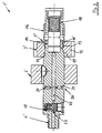
- a respective device 1, 1 ' comprises as drive-combined circulation displacement pumps preferably externally toothed gear pumps 2, 2 'and 3, 3' as respective Lubricating oil pumps for internal combustion engines, not shown.
- each of the devices 1, 1 'of Figures 1 and 2 is a first, driven pump 2, 2' over whose drive shaft 4, 4 'with a second, coaxially arranged, connectable and disconnectable Pump 3, 3 'combined, the coupling and decoupling of the in one with the first pump 2, 2 'promoting common, not shown pressure channel second pump 3, 3 'by means of a controllable, frictionally and positively acting Slip clutch 5, 5 'is effected depending on the delivery pressure or speed.
- the respective slip clutch is in each of the devices 1, 1 ' 5, 5 'controlled by a centrifugal device.
- a pump rotor 6 of the second pump 3 is included a sleeve shaft rotatably mounted on the drive shaft 4 of the first pump 2 7 at 7 'rotatably connected, the sleeve shaft 7 in the free end region is in a rotationally fixed connection with a kelly belt-like grooved disk 8, the spring-loaded as part of the slip clutch 5 a frictional and positive engagement and centrifugal force-controlled clutch jaws 9 provided with splines 10 serves.
- the clutch shoes 10 serving as centrifugal force controlled devices are limited to a support disk 11 which is connected in a rotationally fixed manner to the drive shaft 4 pivotally mounted. Furthermore, the clutch shoes 10 are corresponding the direction of rotation of the drive shaft 4 on the support plate 11 for a self-reinforcing Engagement of the splines 9 in the pulley 8 is arranged.
- a lubricating oil pump of an internal combustion engine is a lubricating oil pump in the area of low machine speeds ensured via both pumps 2 and 3. Is dependent on a predetermined Machine speed with the constant delivery pump 2 alone the required Delivery volume reached, the second pump 3 is decoupled by centrifugal force, the clutch shoes 10 with their wedge profiles 9 controlled by centrifugal force out of engagement are brought with the pulley 8.
- a pump rotor 12 of the second pump 3' is via an opening 13 loose from the drive shaft 4 'of the first pump 2' enforced.
- the opening 13 diametrically arranged cone sections 14 and 14 'form on the one hand with a cone 15 of the drive shaft 4' and on the other hand with a beveled, spring-hydraulically controllable arranged on the drive shaft 4 ' Switching sleeve 16, the slip clutch 5 ', which is hydraulically operated by means of a Centrifugal valve 17 acts on the switching sleeve 16 against the resistance a preloaded clutch spring 18 for delivery pressure or speed dependent Drive interruption of the second pump 3 'is kept released.
- hydraulic medium is over a Annular groove 20 in the drive shaft 4 'via radial channels 21 to a central channel 22, the one end of the drive shaft 4 'by means of the centrifugal force adjustable against a spring force Valve 17 is closable. Until a predetermined one is reached At the engine speed, the hydraulic medium flows out of the central channel 22 via an annular groove 23 of the centrifugal valve 17.
- the second pump 3' When the predetermined one is reached Machine speed and thus that of the constantly pumping pump 2 'reached flow rate, the second pump 3' is decoupled in that the delivery pressure effective on the piston 19 and generated by the first pump 2 ' Piston 19 axially displaces against the preloaded clutch spring 18 to release the switching sleeve 16 from frictional and positive engagement with the cone section 14 'or the engagement of the cone section 14 with the cone 15 of the drive shaft 4 '.
Landscapes
- Engineering & Computer Science (AREA)
- Mechanical Engineering (AREA)
- General Engineering & Computer Science (AREA)
- One-Way And Automatic Clutches, And Combinations Of Different Clutches (AREA)
- Structures Of Non-Positive Displacement Pumps (AREA)
- Rotary Pumps (AREA)
Abstract
Description
- Figur 1
- eine erfindungsgemäße Vorrichtung mit einer fliehkraftgesteuerten Rutschkupplung,
- Figur 2
- eine weitere erfindungsgemäße Vorrichtung mit einer Rutschkupplung, die über ein fliehkraftgesteuertes Ventil hydraulisch beaufschlagt ist.
Claims (4)
- Vorrichtung mit antriebskombinierten Umlaufverdrängerpumpen, insbesondere außenverzahnte Zahnradpumpen, vor allem für Brennkraftmaschinen,bei der eine erste, angetriebene Pumpe (2, 2') über deren Antriebswelle (4, 4') mit einer zweiten gleichachsig angeordneten, zu- und abkoppelbaren Pumpe (3, 3') kombiniert ist, wobeidie Zu- und Abkoppelung der in einen mit der ersten Pumpe (2, 2') gemeinsamen Druckkanal fördernden zweiten Pumpe (3, 3') mittels einer reib- und formschlüssig wirkenden, steuerbaren Rutschkupplung (5, 5') förderdruck- bzw. drehzahlabhängig bewirkt ist,
dadurch gekennzeichnet,dass eine jeweilige Rutschkupplung (5, 5') über eine fliehkraftgesteuerte Einrichtung (8, 10; 17) gesteuert ist. - Vorrichtung nach Anspruch 1, dadurch gekennzeichnet,dass ein Pumpenrotor (6) der zweiten Pumpe (3) mit einer auf der Antriebswelle (4) der ersten Pumpe (2) drehbeweglich gelagerten Hülsenwelle (7) drehfest verbunden ist, unddie Hülsenwelle (7) im freien Endbereich mit einer keilriemenartig gestalteten Rillenscheibe (8) in drehfester Verbindung steht, wobeidie Rillenscheibe (8) als Teil einer Rutschkupplung (5) einem reib- und formschlüssigen Eingriff federbelasteter und fliehkraftgesteuerter, mit Keilprofilen (9) versehener Kupplungsbacken (10) dient, diean einer mit der Antriebswelle (4) drehfest verbundenen Tragscheibe (11) schwenkbeweglich gelagert sind.
- Vorrichtung nach Anspruch 2, dadurch gekennzeichnet, dass die Kupplungsbacken (10) an der Tragscheibe (11) entsprechend einem selbstverstärkenden Eingriff in die Rillenscheibe (8) angeordnet sind.
- Vorrichtung nach Anspruch 1, dadurch gekennzeichnet,dass ein Pumpenrotor (12) der zweiten Pumpe (3') über eine Durchbrechung (13) von der Antriebswelle (4') der ersten Pumpe (2') lose durchsetzt ist, undin der Durchbrechung (13) diametral angeordnete Kegelabschnitte (14, 14') einerseits mit einem Konus (15) der Antriebswelle (4') und andererseits mit einer angeschrägten, auf der Antriebswelle (4') federhydraulisch steuerbar angeordneten Schalthülse (16) eine Rutschkupplung (5') bilden, dieüber die hydraulisch mittels eines fliehkraftgesteuerten Ventils (17) beaufschlagte Schalthülse (16) gegen den Widerstand einer vorgespannten Kupplungsfeder (18) zur förderdruck- bzw. drehzahlabhängigen Antriebsunterbrechung der zweiten Pumpe (3') gelöst gehalten ist.
Applications Claiming Priority (2)
| Application Number | Priority Date | Filing Date | Title |
|---|---|---|---|
| DE1999150206 DE19950206A1 (de) | 1999-10-19 | 1999-10-19 | Vorrichtung mit antriebskombinierten Umlaufverdrängerpumpen, insbesondere außenverzahnte Zahnradpumpen, vor allem für Brennkraftmaschinen |
| DE19950206 | 1999-10-19 |
Publications (2)
| Publication Number | Publication Date |
|---|---|
| EP1094221A1 true EP1094221A1 (de) | 2001-04-25 |
| EP1094221B1 EP1094221B1 (de) | 2007-11-28 |
Family
ID=7926080
Family Applications (1)
| Application Number | Title | Priority Date | Filing Date |
|---|---|---|---|
| EP20000120799 Expired - Lifetime EP1094221B1 (de) | 1999-10-19 | 2000-09-23 | Vorrichtung mit antriebskombinierten Umlaufverdrängerpumpen |
Country Status (3)
| Country | Link |
|---|---|
| EP (1) | EP1094221B1 (de) |
| DE (2) | DE19950206A1 (de) |
| ES (1) | ES2293880T3 (de) |
Cited By (3)
| Publication number | Priority date | Publication date | Assignee | Title |
|---|---|---|---|---|
| WO2002079662A1 (en) * | 2001-03-30 | 2002-10-10 | Eaton Corporation | Clutch assembly with a gear pump |
| EP1277960A3 (de) * | 2001-07-17 | 2003-11-05 | Pierburg S.p.A. | Pumpe mit variabler Fördermenge |
| WO2011095148A3 (de) * | 2010-02-04 | 2012-06-21 | Ixetic Bad Homburg Gmbh | Tandempumpe mit einer schaltbaren kupplung zwischen den beiden pumpen |
Families Citing this family (4)
| Publication number | Priority date | Publication date | Assignee | Title |
|---|---|---|---|---|
| DE102005032226A1 (de) * | 2005-07-09 | 2007-01-18 | Daimlerchrysler Ag | Schmiermittelversorgungssystem eines Kraftfahrzeugs |
| DE102014204946A1 (de) * | 2014-03-18 | 2015-09-24 | Mahle International Gmbh | Pumpenanordnung |
| DE102018212497B4 (de) * | 2018-07-26 | 2026-01-29 | Eckerle Technologies GmbH | Fluidfördereinrichtung |
| DE102023212881A1 (de) * | 2023-12-18 | 2025-06-18 | Zf Friedrichshafen Ag | Pumpensystem |
Citations (5)
| Publication number | Priority date | Publication date | Assignee | Title |
|---|---|---|---|---|
| DE869156C (de) | 1950-12-07 | 1953-03-02 | Georg Gert Frederichs | Hydraulisches Pumpenaggregat |
| DE4134219A1 (de) | 1990-10-29 | 1992-04-30 | Volkswagen Ag | Zahnradpumpe mit veraenderbarem foerdervolumen |
| US5290153A (en) * | 1993-03-09 | 1994-03-01 | General Motors Corporation | Two stage pump assembly |
| US5326232A (en) * | 1993-04-20 | 1994-07-05 | General Motors Corporation | Two stage pump assembly with mechanical disconnect |
| DE4317645C2 (de) | 1993-05-27 | 1997-02-20 | Iav Motor Gmbh | Regelbare Zahnradpumpe |
Family Cites Families (2)
| Publication number | Priority date | Publication date | Assignee | Title |
|---|---|---|---|---|
| US2433954A (en) * | 1944-01-20 | 1948-01-06 | Clark Equipment Co | Fluid pump and control therefor |
| US3941505A (en) * | 1973-06-25 | 1976-03-02 | Trw Inc. | Method and apparatus for pumping fuel |
-
1999
- 1999-10-19 DE DE1999150206 patent/DE19950206A1/de not_active Withdrawn
-
2000
- 2000-09-23 ES ES00120799T patent/ES2293880T3/es not_active Expired - Lifetime
- 2000-09-23 EP EP20000120799 patent/EP1094221B1/de not_active Expired - Lifetime
- 2000-09-23 DE DE50014811T patent/DE50014811D1/de not_active Expired - Lifetime
Patent Citations (5)
| Publication number | Priority date | Publication date | Assignee | Title |
|---|---|---|---|---|
| DE869156C (de) | 1950-12-07 | 1953-03-02 | Georg Gert Frederichs | Hydraulisches Pumpenaggregat |
| DE4134219A1 (de) | 1990-10-29 | 1992-04-30 | Volkswagen Ag | Zahnradpumpe mit veraenderbarem foerdervolumen |
| US5290153A (en) * | 1993-03-09 | 1994-03-01 | General Motors Corporation | Two stage pump assembly |
| US5326232A (en) * | 1993-04-20 | 1994-07-05 | General Motors Corporation | Two stage pump assembly with mechanical disconnect |
| DE4317645C2 (de) | 1993-05-27 | 1997-02-20 | Iav Motor Gmbh | Regelbare Zahnradpumpe |
Cited By (3)
| Publication number | Priority date | Publication date | Assignee | Title |
|---|---|---|---|---|
| WO2002079662A1 (en) * | 2001-03-30 | 2002-10-10 | Eaton Corporation | Clutch assembly with a gear pump |
| EP1277960A3 (de) * | 2001-07-17 | 2003-11-05 | Pierburg S.p.A. | Pumpe mit variabler Fördermenge |
| WO2011095148A3 (de) * | 2010-02-04 | 2012-06-21 | Ixetic Bad Homburg Gmbh | Tandempumpe mit einer schaltbaren kupplung zwischen den beiden pumpen |
Also Published As
| Publication number | Publication date |
|---|---|
| ES2293880T3 (es) | 2008-04-01 |
| EP1094221B1 (de) | 2007-11-28 |
| DE19950206A1 (de) | 2001-04-26 |
| DE50014811D1 (de) | 2008-01-10 |
Similar Documents
| Publication | Publication Date | Title |
|---|---|---|
| DE3409690C1 (de) | Kupplungsanordnung eines Antriebsaggregates eines Fahrzeuges mit einer hydrodynamischen Strömungskupplung und einer Reibkupplung | |
| DE2215922B2 (de) | Hydraulisch betätigbare Wechselreibungskupplung | |
| DE19945475A1 (de) | Kraftübertragungseinrichtung | |
| EP1914434A2 (de) | Drehmomentübertragungseinrichtung | |
| DE69031689T2 (de) | Stufenlos verstellbares Getriebe | |
| DE2734630B1 (de) | Zweistraengiges stufenlos einstellbares Kegelscheibenumschlingungsgetriebe mit gleichmaessiger Lastverteilung | |
| EP1094221A1 (de) | Vorrichtung mit antriebskombinierten Umlaufverdrängerpumpen | |
| DE2139600A1 (de) | Von der Antriebsmaschine eines Fahrzeugs abgeleiteter Antrieb für dessen Hilfsgeräte | |
| DE2633973C2 (de) | Kupplung | |
| EP1209380A2 (de) | Kegelscheibengetriebe | |
| DE3827946C2 (de) | ||
| DE102019116932A1 (de) | Verteilergetriebe mit schmiermittelführung | |
| DE2704940A1 (de) | Traegheitsarme kupplungs- und bremsvorrichtung | |
| DE10226861B4 (de) | Stufenlos regelbares Umschlingungsgetriebe | |
| DE68910132T2 (de) | Eine momentbegrenzende kupplungsanordnung. | |
| DE2353084C2 (de) | Gewindebohrfutter | |
| DE102007045588A1 (de) | Drehmomentübertragungseinrichtung | |
| WO2005064180A1 (de) | Kupplungslamelle | |
| DE69722640T2 (de) | Mit öl gekühlte scheibenkupplung | |
| DE3013893C2 (de) | ||
| DE4318475B4 (de) | Scheibensatz für ein stufenloses Umschlingungsgetriebe | |
| DE834178C (de) | Ausruecklager fuer Kupplungen, insbesondere fuer Kraftfahrzeuge | |
| DE3135995A1 (de) | Nasslaufkupplung | |
| DE2853028A1 (de) | Stufenlos einstellbares kegelscheiben-umschlingungsgetriebe | |
| DE2658541C2 (de) | Hydraulisch schaltbare Reibungskupplung |
Legal Events
| Date | Code | Title | Description |
|---|---|---|---|
| PUAI | Public reference made under article 153(3) epc to a published international application that has entered the european phase |
Free format text: ORIGINAL CODE: 0009012 |
|
| AK | Designated contracting states |
Kind code of ref document: A1 Designated state(s): DE ES FR GB IT |
|
| AX | Request for extension of the european patent |
Free format text: AL;LT;LV;MK;RO;SI |
|
| 17P | Request for examination filed |
Effective date: 20011019 |
|
| AKX | Designation fees paid |
Free format text: DE ES FR GB IT |
|
| RAP1 | Party data changed (applicant data changed or rights of an application transferred) |
Owner name: BAYERISCHE MOTOREN WERKE AKTIENGESELLSCHAFT |
|
| GRAP | Despatch of communication of intention to grant a patent |
Free format text: ORIGINAL CODE: EPIDOSNIGR1 |
|
| RIC1 | Information provided on ipc code assigned before grant |
Ipc: F04C 15/00 20060101AFI20070828BHEP |
|
| GRAS | Grant fee paid |
Free format text: ORIGINAL CODE: EPIDOSNIGR3 |
|
| GRAA | (expected) grant |
Free format text: ORIGINAL CODE: 0009210 |
|
| AK | Designated contracting states |
Kind code of ref document: B1 Designated state(s): DE ES FR GB IT |
|
| REG | Reference to a national code |
Ref country code: GB Ref legal event code: FG4D Free format text: NOT ENGLISH |
|
| GBT | Gb: translation of ep patent filed (gb section 77(6)(a)/1977) |
Effective date: 20071128 |
|
| REF | Corresponds to: |
Ref document number: 50014811 Country of ref document: DE Date of ref document: 20080110 Kind code of ref document: P |
|
| REG | Reference to a national code |
Ref country code: ES Ref legal event code: FG2A Ref document number: 2293880 Country of ref document: ES Kind code of ref document: T3 |
|
| ET | Fr: translation filed | ||
| PLBE | No opposition filed within time limit |
Free format text: ORIGINAL CODE: 0009261 |
|
| STAA | Information on the status of an ep patent application or granted ep patent |
Free format text: STATUS: NO OPPOSITION FILED WITHIN TIME LIMIT |
|
| 26N | No opposition filed |
Effective date: 20080829 |
|
| REG | Reference to a national code |
Ref country code: FR Ref legal event code: PLFP Year of fee payment: 17 |
|
| REG | Reference to a national code |
Ref country code: FR Ref legal event code: PLFP Year of fee payment: 18 |
|
| REG | Reference to a national code |
Ref country code: FR Ref legal event code: PLFP Year of fee payment: 19 |
|
| PGFP | Annual fee paid to national office [announced via postgrant information from national office to epo] |
Ref country code: IT Payment date: 20190920 Year of fee payment: 20 Ref country code: FR Payment date: 20190923 Year of fee payment: 20 Ref country code: DE Payment date: 20190924 Year of fee payment: 20 |
|
| PGFP | Annual fee paid to national office [announced via postgrant information from national office to epo] |
Ref country code: GB Payment date: 20190924 Year of fee payment: 20 |
|
| PGFP | Annual fee paid to national office [announced via postgrant information from national office to epo] |
Ref country code: ES Payment date: 20191023 Year of fee payment: 20 |
|
| REG | Reference to a national code |
Ref country code: GB Ref legal event code: PE20 Expiry date: 20200922 |
|
| PG25 | Lapsed in a contracting state [announced via postgrant information from national office to epo] |
Ref country code: GB Free format text: LAPSE BECAUSE OF EXPIRATION OF PROTECTION Effective date: 20200922 |
|
| REG | Reference to a national code |
Ref country code: ES Ref legal event code: FD2A Effective date: 20220110 |
|
| PG25 | Lapsed in a contracting state [announced via postgrant information from national office to epo] |
Ref country code: ES Free format text: LAPSE BECAUSE OF EXPIRATION OF PROTECTION Effective date: 20200924 |