EP1088674B1 - Einheit und Verfahren zum Steuern eines in einem Drucker zu verwendenden Motors und Speichermedien zum Speichern des Steuerprogrammes - Google Patents
Einheit und Verfahren zum Steuern eines in einem Drucker zu verwendenden Motors und Speichermedien zum Speichern des Steuerprogrammes Download PDFInfo
- Publication number
- EP1088674B1 EP1088674B1 EP00307781A EP00307781A EP1088674B1 EP 1088674 B1 EP1088674 B1 EP 1088674B1 EP 00307781 A EP00307781 A EP 00307781A EP 00307781 A EP00307781 A EP 00307781A EP 1088674 B1 EP1088674 B1 EP 1088674B1
- Authority
- EP
- European Patent Office
- Prior art keywords
- motor
- control
- current
- stoppage
- carriage
- Prior art date
- Legal status (The legal status is an assumption and is not a legal conclusion. Google has not performed a legal analysis and makes no representation as to the accuracy of the status listed.)
- Expired - Lifetime
Links
Images




Classifications
-
- B—PERFORMING OPERATIONS; TRANSPORTING
- B41—PRINTING; LINING MACHINES; TYPEWRITERS; STAMPS
- B41J—TYPEWRITERS; SELECTIVE PRINTING MECHANISMS, i.e. MECHANISMS PRINTING OTHERWISE THAN FROM A FORME; CORRECTION OF TYPOGRAPHICAL ERRORS
- B41J19/00—Character- or line-spacing mechanisms
- B41J19/18—Character-spacing or back-spacing mechanisms; Carriage return or release devices therefor
- B41J19/20—Positive-feed character-spacing mechanisms
- B41J19/202—Drive control means for carriage movement
-
- G—PHYSICS
- G05—CONTROLLING; REGULATING
- G05B—CONTROL OR REGULATING SYSTEMS IN GENERAL; FUNCTIONAL ELEMENTS OF SUCH SYSTEMS; MONITORING OR TESTING ARRANGEMENTS FOR SUCH SYSTEMS OR ELEMENTS
- G05B19/00—Program-control systems
- G05B19/02—Program-control systems electric
- G05B19/18—Numerical control [NC], i.e. automatically operating machines, in particular machine tools, e.g. in a manufacturing environment, so as to execute positioning, movement or co-ordinated operations by means of program data in numerical form
- G05B19/416—Numerical control [NC], i.e. automatically operating machines, in particular machine tools, e.g. in a manufacturing environment, so as to execute positioning, movement or co-ordinated operations by means of program data in numerical form characterised by control of velocity, acceleration or deceleration
- G05B19/4163—Adaptive control of feed or cutting velocity
-
- G—PHYSICS
- G05—CONTROLLING; REGULATING
- G05B—CONTROL OR REGULATING SYSTEMS IN GENERAL; FUNCTIONAL ELEMENTS OF SUCH SYSTEMS; MONITORING OR TESTING ARRANGEMENTS FOR SUCH SYSTEMS OR ELEMENTS
- G05B2219/00—Program-control systems
- G05B2219/30—Nc systems
- G05B2219/37—Measurements
- G05B2219/37388—Acceleration or deceleration, inertial measurement
-
- G—PHYSICS
- G05—CONTROLLING; REGULATING
- G05B—CONTROL OR REGULATING SYSTEMS IN GENERAL; FUNCTIONAL ELEMENTS OF SUCH SYSTEMS; MONITORING OR TESTING ARRANGEMENTS FOR SUCH SYSTEMS OR ELEMENTS
- G05B2219/00—Program-control systems
- G05B2219/30—Nc systems
- G05B2219/43—Speed, acceleration, deceleration control ADC
- G05B2219/43006—Acceleration, deceleration control
-
- G—PHYSICS
- G05—CONTROLLING; REGULATING
- G05B—CONTROL OR REGULATING SYSTEMS IN GENERAL; FUNCTIONAL ELEMENTS OF SUCH SYSTEMS; MONITORING OR TESTING ARRANGEMENTS FOR SUCH SYSTEMS OR ELEMENTS
- G05B2219/00—Program-control systems
- G05B2219/30—Nc systems
- G05B2219/43—Speed, acceleration, deceleration control ADC
- G05B2219/43016—Acceleration, deceleration as function of feed rate override
-
- G—PHYSICS
- G05—CONTROLLING; REGULATING
- G05B—CONTROL OR REGULATING SYSTEMS IN GENERAL; FUNCTIONAL ELEMENTS OF SUCH SYSTEMS; MONITORING OR TESTING ARRANGEMENTS FOR SUCH SYSTEMS OR ELEMENTS
- G05B2219/00—Program-control systems
- G05B2219/30—Nc systems
- G05B2219/45—Nc applications
- G05B2219/45187—Printer
Definitions
- the present invention relates generally to a control unit and method for controlling a motor for use in a printer, and a storage medium storing a control program. More specifically, the invention is used for controlling the speed of a motor for driving a carriage of a serial printer.
- PID control is performed based on a deviation of a counted value of the output pulses of an encoder rotating in accordance with the rotation of the CR motor from a target position (target number of pulses).
- the carriage will stop, however, at a position apart from the target position due to change in carriage inertia (moment of inertia), loads, motor currents, and so on.
- a special control (logical seek) is required to stop the carriage at the target position. Such a control is very complex and takes long.
- EP 0659572 discloses a printer and method of controlling the printer in which a pulse generator generates timing pulses in a number proportional to the movement of a carriage mounting the printer's recording head.
- the current value I f corresponds to a speed of the object under constant speed control just before a transition from the constant speed control to the deceleration control.
- control program code for controlling a motor for use in a printer, including: first program code means for calculating inertia of a carriage based on angular acceleration of a carriage motor under acceleration control of the carriage and current values to be applied to the carriage motor under the acceleration control and constant speed control of the carriage; second program code means for calculating a stoppage current to be used for stopping the carriage at a target position based on the calculated inertia, an angular velocity of the motor under deceleration control of the carriage, the current value to be applied to the motor under the constant speed control of the carriage, and a stoppage constant T BRK ; and third program code means for stopping the carriage by applying the calculated stoppage current to the motor during the stoppage control.
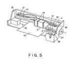
- the pump unit 36 When the nozzle opening row of the recording head 9 is clogged with ink, or when the cartridge 34 is exchanged or the like to force the recording head 9 to discharge ink, the pump unit 36 is operated in the sealed state of the recording head 9, to suck ink out of the nozzle opening row by a negative pressure from the pump unit 36. Thus, dust and paper powder adhering to a portion near the nozzle opening row are cleaned. Moreover, bubbles of the recording head 9, together with ink, are discharged to a cap 37.
- the phase of the pulse ENC-A is different from the phase of the pulse ENC-B by 90 degrees.
- the encoder 4 is designed so that the phase of the pulse ENC-A is advanced from the pulse ENC-B by 90 degrees as shown in FIG. 7(a) when the CR motor 4 is normally rotating, i.e., when the carriage 3 is moving a main scanning direction, and the phase of the pulse ENC-A lags behind the pulse ENC-B by 90 degrees as shown in FIG. 7(b) when the CR motor 4 is reversely rotating.
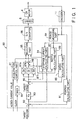
- the controller 80 comprises a position calculating part 81, a subtracter 82, a target speed calculating part 83, a period measuring part 84, a speed calculating part 85, a subtracter 86, a proportional element 87a, an integrating element 87b, a differentiating element 87c, an adder 89, a timer 90, an acceleration control part 91, a stoppage control part 92 having an inertia calculating part 93 and a stoppage current calculating part 94, a selection part 95 and a D/A converter 96.
- the position calculating part 6a is designed to detect the leading and trailing edges of each of the output pulses ENC-A and ENC-B of the encoder 11 to count the number of the detected edges, and to calculate the position of the carriage 3 on the basis of the counted value. In this counting, when the CR motor 4 is normally rotating, if one edge is detected, " +1" is added, and when the CR motor 4 is reversely rotating, if one edge is detected," -1" is added.
- Each of the periods of the pulses ENC-A and ENC-B is equal to the distance between adjacent slits of the code plate 12, and the phase of the pulse ENC-A is different from the phase of the pulse ENC-B by 90 degrees.
- the subtracter 82 is designed to calculate a position deviation of the actual position of the carriage 3, which is obtained by the position calculating part 81, from a target position which is fed from the CPU 16.
- the proportional element 87a is designed to multiply the speed deviation by a constant Gp to output the multiplied result.
- the integrating element 87b is designed to integrate a value which is obtained by multiplying the speed deviation by a constant Gi.
- the differentiating element 87c is designed to multiply a difference between the current speed deviation and the last speed variation by a constant Gd to output the multiplied result. Furthermore, the operations in the proportional element 87a, integrating element 87b and differentiating element 87c are carried out every one period of the output pulse ENC-A of the encoder 11, i.e., in synchronism with the leading edge of the output pulse ENC-A.
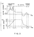
- the timer 90 After the start-up command signal is received, the timer 90 generates a timer interruption signal for every predetermined time. Every time the acceleration control part 91 receives the timer interruption signal, the acceleration control part 91 integrates a predetermined current value (e.g., 20 mA) into the start-up initial current value I o , to feed the integrated current value to the D/A converter 96 via the selection part 95. Then, the integrated current value is converted into an analog current by the D/A converter 96 to be fed to the driver 5. Then, the CR motor is driven by the driver 5 so that the value of the current supplied to the CR motor 4 is the integrated current value, so that the speed of the CR motor 4 increases (see FIG. 3(b)). Therefore, the current value supplied to the CR motor is step-wise as shown in FIG. 3(a).
- a predetermined current value e.g. 20 mA
- the acceleration control part 91 controls the CR motor 4 so as to reduce the current, which is supplied to the CR motor 4, when the speed of the CR motor 4 becomes a predetermined speed V 1 (see time t 2 ). At this time, the speed of the CR motor 4 further increases. However, when the speed of the CR motor 4 reaches a predetermined speed V c (see time t 3 in FIG. 3(b)), the selection part 95 selects the output of the PID control system, i.e., the output of the adder 89, to carry out the PID control.
- One inertia calculation is usually executed for each one pass (one main scanning operation during printing process). However, this is not a must, and it is preferable that an inertia calculation is executed based on data necessary for the calculation, which have been stored at timing, such as, just before stoppage that will not affect encoder periods.
- the calculated inertia is used not only for stoppage control but also for judging the status of the printing drive section to control the drive section in a desired status. Moreover, inertia can be updated at any timing, such as, per page, after cleaning, and so on. Inertia calculation may be conducted, however, inertia that is updated for the first time after same change has occurred in the former inertia can be used.
- the second preferred embodiment will be disclosed with reference to FIG. 9.
- the second embodiment is a method of controlling a motor for use in a printer. A control procedure is shown in FIG. 9.
- a stoppage current for stopping the carriage 3 at the target position based on the calculated inertia, an angular velocity of the CR motor 4 at carriage deceleration, a current value applied to the CR motor 4 under carriage constant control, and the stoppage constant T BRK (see step F2 in FIG. 9).
- the steps F2 and F3 in FIG. 9 are the steps for controlling a current applied to the CR motor 4 with the calculated inertia.
- a stoppage current is calculated according to inertia of the carriage 3 and the CR motor 4 is controlled based on the calculated stoppage current, thus achieving rapid and precise carriage stoppage at the target position.
- the computer system 130 comprises a computer body 130 including a CPU, a display unit 132, such as a CRT, an input unit 133, such as a keyboard or mouse, and a printer 134 for carrying out a print.
- a computer body 130 including a CPU, a display unit 132, such as a CRT, an input unit 133, such as a keyboard or mouse, and a printer 134 for carrying out a print.
- the computer body 131 comprises an internal memory 135 of a RAM, and a built-in or exterior memory unit 136.
- a flexible or floppy disk (FD) drive 137, a CD-ROM drive 138 and a hard disk drive (HD) unit 139 are mounted as the memory unit 136.
- a flexible disk or floppy disk (FD) 141 which is inserted into a slot of the FD drive 137 to be used, a CD-ROM 142 which is used for the CD-ROM drive 138, or the like is used as a storage medium 140 for use in the memory unit 136.
- the FD 141 or the CD-ROM 142 is used as the storage medium for use in a typical computer system.
- the control program of the present invention may be recorded in, e.g., a ROM chip 143 serving as a nonvolatile memory which is built in the printer 134.
- the storage medium may be any one of FDs, CD-ROMs, MOs (Magneto-Optical) disks, DVDs (Digital Versatile Disks), other optical recording disks, card memories, and magnetic tapes.
Landscapes
- Engineering & Computer Science (AREA)
- Human Computer Interaction (AREA)
- Manufacturing & Machinery (AREA)
- Physics & Mathematics (AREA)
- General Physics & Mathematics (AREA)
- Automation & Control Theory (AREA)
- Character Spaces And Line Spaces In Printers (AREA)
- Accessory Devices And Overall Control Thereof (AREA)
- Control Of Electric Motors In General (AREA)
- Control Of Direct Current Motors (AREA)
Claims (12)
- Steuereinheit zum Steuern eines Motors zum Einsatz in einem Drucker, die umfasst:einen Geschwindigkeitssteuerteil (83, 86, 87a, 87b, 87c, 89, 95, 96), der so eingerichtet ist, dass er ein zu steuerndes Objekt, das von dem Motor (4) angetrieben wird, durch Beschleunigungssteuerung, Konstantgeschwindigkeitssteuerung, Abbremssteuerung und Anhaltesteuerung steuert, indem er einen dem Motor zuzuführenden Strom steuert; und gekennzeichnet durch:einen Trägheitsberechnungsteil (93), der so eingerichtet ist, dass er Trägheit des Objektes auf Basis von Winkelbeschleunigung des Motors bei Beschleunigungssteuerung des Objektes und an den Motor bei der Beschleunigungssteuerung und der Konstantgeschwindigkeitssteuerung des Objektes anzulegender Stromwerte steuert, wobei der Geschwindigkeitssteuerteil so eingerichtet ist, dass er die berechnete Beschleunigung nutzt, um den während der Anhaltesteuerung an den Motor anzulegenden Strom zu steuern.
- Steuereinheit zum Steuern eines Motors zum Einsatz in einem Drucker nach Anspruch 1, die des Weiteren einen Anhaltestrom-Berechnungsteil (94) umfasst, der so eingerichtet ist, dass er einen Anhaltestrom, der zum Anhalten des Objektes an einer Sollposition zu nutzen ist, auf Basis der berechneten Trägheit, einer Winkelgeschwindigkeit des Motors bei der Abbremssteuerung des Objektes, des Stromwertes des Motors bei der Konstantgeschwindigkeitssteuerung des Objektes und einer Anhaltkonstante TBRK berechnet, wobei der Geschwindigkeitssteuerteil so eingerichtet ist, dass er Steuerung zum Anhalten des Objektes durchführt, indem er den berechneten Anhaltestrom anlegt.
- Steuereinheit zum Steuern eines Motors zum Einsatz in einem Drucker nach Anspruch 2, wobei ein vorgegebener Stromwert lacc an den Motor in einem Konstantstrom-Beschleunigungsbereich bei der Beschleunigungssteuerung zum Beschleunigen des Objektes angelegt wird und der Trägheitsberechnungsteil so eingerichtet ist, dass er Winkelbeschleunigung Δω/Δt in dem Konstantstrom-Beschleunigungsbereich berechnet und Trägheit J des Objektes auf Basis der Winkelbeschleunigung Δω/Δt, eines Stromwertes If, der an den Motor bei der Konstantgeschwindigkeitssteuerung des Objektes anzulegen ist, und des Stromwertes lacc berechnet.
- Steuereinheit zum Steuern eines Motors zum Einsatz in einem Drucker nach Anspruch 3, wobei der Stromwert If einer Geschwindigkeit des Objektes bei Konstantgeschwindigkeitssteuerung unmittelbar vor einem Übergang von der Konstantgeschwindigkeitssteuerung zu der Abwehrbremssteuerung entspricht.
- Steuereinheit zum Steuern eines Motors zum Einsatz in einem Drucker nach Anspruch 2, wobei der Anhaltestrom-Berechnungsteil (94) so eingerichtet ist, dass er eine Winkelgeschwindigkeit bei Abbremssteuerung unmittelbar vor einem Übergang von der Abbremssteuerung zu der Anhaltesteuerung als die Winkelgeschwindigkeit des Motors nutzt.
- Steuereinheit zum Steuern eines Motors zum Einsatz in einem Drucker nach Anspruch 1, die des Weiteren einen Periodenmessteil (84) umfasst, der so eingerichtet ist, dass er eine Periode jedes Ausgangsimpulses eines Kodierers misst, der sich Drehung des Motors entsprechend dreht, wobei die Winkelbeschleunigung und die Winkelgeschwindigkeit des Motors auf Basis des Ausgangs des Periodenmessteils (84) berechnet werden.
- Steuereinheit zum Steuern eines Motors zum Einsatz in einem Drucker nach Anspruch 1, wobei die Anhaltekonstante TBRK auf Basis des Stromwertes, der bei der Konstantgeschwindigkeitssteuerung an den Motor anzulegen ist, und einer Positionsabweichung einer Ist-Position des Motors von der Soll-Position bestimmt wird.
- Steuereinheit zum Steuern eines Motors zum Einsatz in einem Drucker nach Anspruch 1, wobei der Motor ein Wagenmotor zum Antreiben eines Wagens ist.
- Verfahren zum Steuern eines Motors zum Einsatz in einem Drucker, das die folgenden Schritte umfasst:Berechnen von Trägheit eines durch den Motor anzutreibenden Objektes auf Basis von Winkelbeschleunigung des Motors bei Beschleunigungssteuerung des Objektes und Stromwerten, die bei der Beschleunigungssteuerung und der Konstantgeschwindigkeitssteuerung des Objektes an den Motor anzulegen sind; undSteuern eines an den Motor während der Anhaltesteuerung anzulegenden Stroms mittels der berechneten Trägheit.
- Verfahren zum Steuern eines Motors zum Einsatz in einem Drucker nach Anspruch 9, wobei der Schritt des Steuern des Stroms die folgenden Schritte einschließt:Berechnen eines Anhaltestroms, der zum Anhalten des Objektes an einer Soll-Position zu nutzen ist, auf Basis der berechneten Trägheit, einer Winkelgeschwindigkeit des Motors bei Abbremssteuerung des Objektes, des Stromwertes des Motors bei der Konstantgeschwindigkeitssteuerung des Objektes und einer Anhalte-Konstante TBRK, undAnhalten des Objektes durch Anlegen des berechneten Anhaltestroms an den Motor.
- Verfahren zum Steuern eines Motors zum Einsatz in einem Drucker nach Anspruch 9, wobei das Objekt ein Wagen eines Zeichendruckers ist.
- Computerlesbares Speichermedium, das Steuer-Programmcode zum Steuern eines Motors zum Einsatz in einem Drucker speichert, das umfasst:erste Programmcodemittel zum Berechnen von Trägheit eines Wagens auf Basis von Winkelbeschleunigung eines Wagenmotors bei Beschleunigungssteuerung des Wagens und Stromwerten, die bei der Beschleunigungssteuerung und Konstantgeschwindigkeitssteuerung des Wagens an den Wagenmotor anzulegen sind;zweite Programmcodemittel zum Berechnen eines Anhaltestroms, der zum Anhalten des Wagens an einer Soll-Position zu nutzen ist, auf Basis der berechneten Trägheit, einer Winkelgeschwindigkeit des Motors bei Abbremssteuerung des Wagens, des Stromwertes, der bei der Konstantgeschwindigkeitssteuerung des Wagens an den Motor anzulegen ist, und einer Anhalte-Konstante TBRK; unddritte Programmcodemittel zum Anhalten des Wagens durch Anlegen des berechneten Anhaltestroms an den Motor während der Anhaltesteuerung.
Applications Claiming Priority (4)
| Application Number | Priority Date | Filing Date | Title |
|---|---|---|---|
| JP27480699 | 1999-09-28 | ||
| JP27480699 | 1999-09-28 | ||
| JP2000167930A JP2001169584A (ja) | 1999-09-28 | 2000-06-05 | プリンタ用モータの制御装置およびその制御方法ならびに制御プログラムを記録した記録媒体 |
| JP2000167930 | 2000-06-05 |
Publications (2)
| Publication Number | Publication Date |
|---|---|
| EP1088674A1 EP1088674A1 (de) | 2001-04-04 |
| EP1088674B1 true EP1088674B1 (de) | 2005-12-14 |
Family
ID=26551205
Family Applications (1)
| Application Number | Title | Priority Date | Filing Date |
|---|---|---|---|
| EP00307781A Expired - Lifetime EP1088674B1 (de) | 1999-09-28 | 2000-09-08 | Einheit und Verfahren zum Steuern eines in einem Drucker zu verwendenden Motors und Speichermedien zum Speichern des Steuerprogrammes |
Country Status (5)
| Country | Link |
|---|---|
| US (2) | US6877837B1 (de) |
| EP (1) | EP1088674B1 (de) |
| JP (1) | JP2001169584A (de) |
| AT (1) | ATE312720T1 (de) |
| DE (1) | DE60024746T2 (de) |
Families Citing this family (18)
| Publication number | Priority date | Publication date | Assignee | Title |
|---|---|---|---|---|
| JP3731060B2 (ja) * | 2000-11-14 | 2006-01-05 | 株式会社日立製作所 | イナーシャ演算方法及び電動機のドライブ装置 |
| US7417400B2 (en) | 2001-07-06 | 2008-08-26 | Seiko Epson Corporation | Motor controller |
| US7585123B2 (en) | 2001-08-22 | 2009-09-08 | Brother Kogyo Kabushiki Kaisha | Image forming apparatus |
| CN1982073B (zh) * | 2001-08-22 | 2011-10-05 | 兄弟工业株式会社 | 图像形成装置及其控制方法 |
| DE10236847A1 (de) * | 2002-08-08 | 2004-02-26 | Dr. Johannes Heidenhain Gmbh | Verfahren zur Bestimmung des Massenträgheitsmomentes eines elektromotorischen Antriebssystems |
| US20050248644A1 (en) * | 2003-07-02 | 2005-11-10 | Lexmark International, Inc. | Method for enhancing perforation speed |
| JP4447891B2 (ja) * | 2003-10-31 | 2010-04-07 | キヤノン株式会社 | Dcモータ制御装置および記録装置 |
| JP4833617B2 (ja) | 2005-03-14 | 2011-12-07 | 株式会社リコー | 印字媒体搬送装置及び印字媒体搬送方法 |
| JP4760090B2 (ja) * | 2005-03-30 | 2011-08-31 | ブラザー工業株式会社 | 搬送装置及び画像形成装置 |
| JP4671115B2 (ja) * | 2005-08-10 | 2011-04-13 | ソニー株式会社 | 駆動モーターの制御方法及びプリンター |
| JP4483812B2 (ja) | 2006-03-24 | 2010-06-16 | セイコーエプソン株式会社 | 印刷装置、スティックスリップ対応方法、プログラム、及び印刷システム |
| JP5649401B2 (ja) * | 2010-10-18 | 2015-01-07 | キヤノン株式会社 | インクジェット記録装置及びキャリッジ制御方法 |
| JP5509028B2 (ja) * | 2010-10-19 | 2014-06-04 | 株式会社ミマキエンジニアリング | プリンタ、制御装置、プログラムおよび記録媒体 |
| JP5928093B2 (ja) | 2012-03-30 | 2016-06-01 | ブラザー工業株式会社 | インクジェット記録装置 |
| US9527272B2 (en) * | 2014-03-07 | 2016-12-27 | Polar 3D Llc | Method for printing a three-dimensional object |
| JP6458689B2 (ja) * | 2015-09-10 | 2019-01-30 | 株式会社デンソー | モータ制御装置 |
| US10855211B2 (en) * | 2018-03-09 | 2020-12-01 | Trane International Inc. | Self-calibration of ECM motor and variable frequency drive inferred torque |
| CN108791910B (zh) * | 2018-05-03 | 2020-09-08 | 深圳市道通智能航空技术有限公司 | 一种油门控制的方法、装置及无人机 |
Family Cites Families (12)
| Publication number | Priority date | Publication date | Assignee | Title |
|---|---|---|---|---|
| US3931562A (en) * | 1968-09-14 | 1976-01-06 | U.S. Philips Corporation | Electric driving arrangement using a stepping motor |
| JPS5612898A (en) * | 1979-07-06 | 1981-02-07 | Hitachi Koki Co Ltd | Controlling method of deceleration of step motor |
| JPS58151885A (ja) * | 1982-03-03 | 1983-09-09 | Hitachi Ltd | モ−タの位置制御方法 |
| JPH0278557A (ja) * | 1988-09-14 | 1990-03-19 | Canon Inc | 記録装置 |
| JPH03290706A (ja) * | 1990-04-09 | 1991-12-20 | Mitsubishi Electric Corp | 数値制御装置 |
| JP2663684B2 (ja) | 1990-07-09 | 1997-10-15 | 富士電機株式会社 | 電動機速度制御系の調整方法 |
| JP3083870B2 (ja) | 1991-05-10 | 2000-09-04 | ファナック株式会社 | 数値制御装置 |
| US5475291A (en) * | 1992-12-10 | 1995-12-12 | Matsushita Electric Industrial Co., Ltd. | Adjustment device for adjusting control parameters of a servo motor and an adjustment method therefor |
| JP3381348B2 (ja) * | 1993-12-27 | 2003-02-24 | セイコーエプソン株式会社 | プリンタ |
| JPH07329388A (ja) * | 1994-06-03 | 1995-12-19 | Canon Inc | 記録装置および情報処理システム |
| JP3479922B2 (ja) | 1994-06-30 | 2003-12-15 | 株式会社安川電機 | 電動機駆動系の負荷定数測定方法 |
| JP3575232B2 (ja) * | 1997-07-03 | 2004-10-13 | 富士ゼロックス株式会社 | 画像出力装置 |
-
2000
- 2000-06-05 JP JP2000167930A patent/JP2001169584A/ja not_active Withdrawn
- 2000-09-08 EP EP00307781A patent/EP1088674B1/de not_active Expired - Lifetime
- 2000-09-08 AT AT00307781T patent/ATE312720T1/de not_active IP Right Cessation
- 2000-09-08 DE DE60024746T patent/DE60024746T2/de not_active Expired - Lifetime
- 2000-09-25 US US09/667,300 patent/US6877837B1/en not_active Expired - Lifetime
-
2005
- 2005-03-04 US US11/071,450 patent/US7147299B2/en not_active Expired - Fee Related
Also Published As
| Publication number | Publication date |
|---|---|
| DE60024746D1 (de) | 2006-01-19 |
| EP1088674A1 (de) | 2001-04-04 |
| JP2001169584A (ja) | 2001-06-22 |
| US20050146555A1 (en) | 2005-07-07 |
| US6877837B1 (en) | 2005-04-12 |
| ATE312720T1 (de) | 2005-12-15 |
| US7147299B2 (en) | 2006-12-12 |
| DE60024746T2 (de) | 2006-07-06 |
Similar Documents
| Publication | Publication Date | Title |
|---|---|---|
| US6747429B2 (en) | Print control system, print control method, and recording medium having recorded print control program | |
| US6877837B1 (en) | Control unit and method for controlling motor for use in printer, and storage medium storing control program | |
| US7712857B2 (en) | Printing apparatus, printing method, program, storage medium, and computer system | |
| EP1072425B1 (de) | Steuereinheit und Verfahren zum Steuern eines Motors zur Vewendung in einem Drucker und Steuerungsprogramm speicherndes Speichermedium | |
| US6390698B1 (en) | Apparatus and method of detecting home position of carriage and storage medium storing home position detection program | |
| US6809489B1 (en) | Print control unit and print control method, and storage medium storing print control program | |
| US6967729B1 (en) | Control unit and method for controlling motor for use in printer, and storage medium storing control program | |
| JP3570617B2 (ja) | Dcモータ制御装置及び制御方法 | |
| JP2001219613A (ja) | モータ制御装置及び制御方法 | |
| JP4265141B2 (ja) | 印刷装置、印刷方法、プログラム及びコンピュータシステム | |
| JP3705061B2 (ja) | モータの制御装置およびその制御方法ならびにモータの制御プログラムを記録した記録媒体 | |
| JP3893853B2 (ja) | プリンタ用モータの制御装置および制御方法 | |
| JP2004034469A (ja) | 印刷装置およびコンピュータシステム | |
| JP2001224189A (ja) | モータ制御方法及び制御装置 | |
| JP3871181B2 (ja) | 印刷制御装置および制御方法ならびに印刷制御プログラムを記録した記録媒体 | |
| JP3849908B2 (ja) | 印刷制御装置および印刷制御方法 | |
| JP2005028715A (ja) | 印刷装置、印刷方法、プログラム及びコンピュータシステム | |
| JP4432055B2 (ja) | プリンタ用モータの制御装置および制御方法 | |
| JP2001078475A (ja) | モータ制御装置及び制御方法 | |
| JP2005200222A (ja) | 印刷制御装置および制御方法ならびに印刷制御プログラムを記録した記録媒体 | |
| JP2009061787A (ja) | 印刷装置及び印刷方法 |
Legal Events
| Date | Code | Title | Description |
|---|---|---|---|
| PUAI | Public reference made under article 153(3) epc to a published international application that has entered the european phase |
Free format text: ORIGINAL CODE: 0009012 |
|
| AK | Designated contracting states |
Kind code of ref document: A1 Designated state(s): AT BE CH CY DE DK ES FI FR GB GR IE IT LI LU MC NL PT SE |
|
| AX | Request for extension of the european patent |
Free format text: AL;LT;LV;MK;RO;SI |
|
| 17P | Request for examination filed |
Effective date: 20010829 |
|
| AKX | Designation fees paid |
Free format text: AT BE CH CY DE DK ES FI FR GB GR IE IT LI LU MC NL PT SE |
|
| 17Q | First examination report despatched |
Effective date: 20050215 |
|
| GRAP | Despatch of communication of intention to grant a patent |
Free format text: ORIGINAL CODE: EPIDOSNIGR1 |
|
| GRAS | Grant fee paid |
Free format text: ORIGINAL CODE: EPIDOSNIGR3 |
|
| GRAA | (expected) grant |
Free format text: ORIGINAL CODE: 0009210 |
|
| AK | Designated contracting states |
Kind code of ref document: B1 Designated state(s): AT BE CH CY DE DK ES FI FR GB GR IE IT LI LU MC NL PT SE |
|
| PG25 | Lapsed in a contracting state [announced via postgrant information from national office to epo] |
Ref country code: NL Free format text: LAPSE BECAUSE OF FAILURE TO SUBMIT A TRANSLATION OF THE DESCRIPTION OR TO PAY THE FEE WITHIN THE PRESCRIBED TIME-LIMIT Effective date: 20051214 Ref country code: LI Free format text: LAPSE BECAUSE OF FAILURE TO SUBMIT A TRANSLATION OF THE DESCRIPTION OR TO PAY THE FEE WITHIN THE PRESCRIBED TIME-LIMIT Effective date: 20051214 Ref country code: CH Free format text: LAPSE BECAUSE OF FAILURE TO SUBMIT A TRANSLATION OF THE DESCRIPTION OR TO PAY THE FEE WITHIN THE PRESCRIBED TIME-LIMIT Effective date: 20051214 Ref country code: BE Free format text: LAPSE BECAUSE OF FAILURE TO SUBMIT A TRANSLATION OF THE DESCRIPTION OR TO PAY THE FEE WITHIN THE PRESCRIBED TIME-LIMIT Effective date: 20051214 Ref country code: FI Free format text: LAPSE BECAUSE OF FAILURE TO SUBMIT A TRANSLATION OF THE DESCRIPTION OR TO PAY THE FEE WITHIN THE PRESCRIBED TIME-LIMIT Effective date: 20051214 Ref country code: AT Free format text: LAPSE BECAUSE OF FAILURE TO SUBMIT A TRANSLATION OF THE DESCRIPTION OR TO PAY THE FEE WITHIN THE PRESCRIBED TIME-LIMIT Effective date: 20051214 |
|
| REG | Reference to a national code |
Ref country code: GB Ref legal event code: FG4D |
|
| REG | Reference to a national code |
Ref country code: CH Ref legal event code: EP |
|
| REG | Reference to a national code |
Ref country code: IE Ref legal event code: FG4D |
|
| REF | Corresponds to: |
Ref document number: 60024746 Country of ref document: DE Date of ref document: 20060119 Kind code of ref document: P |
|
| PG25 | Lapsed in a contracting state [announced via postgrant information from national office to epo] |
Ref country code: DK Free format text: LAPSE BECAUSE OF FAILURE TO SUBMIT A TRANSLATION OF THE DESCRIPTION OR TO PAY THE FEE WITHIN THE PRESCRIBED TIME-LIMIT Effective date: 20060314 Ref country code: GR Free format text: LAPSE BECAUSE OF FAILURE TO SUBMIT A TRANSLATION OF THE DESCRIPTION OR TO PAY THE FEE WITHIN THE PRESCRIBED TIME-LIMIT Effective date: 20060314 Ref country code: SE Free format text: LAPSE BECAUSE OF FAILURE TO SUBMIT A TRANSLATION OF THE DESCRIPTION OR TO PAY THE FEE WITHIN THE PRESCRIBED TIME-LIMIT Effective date: 20060314 |
|
| PG25 | Lapsed in a contracting state [announced via postgrant information from national office to epo] |
Ref country code: ES Free format text: LAPSE BECAUSE OF FAILURE TO SUBMIT A TRANSLATION OF THE DESCRIPTION OR TO PAY THE FEE WITHIN THE PRESCRIBED TIME-LIMIT Effective date: 20060325 |
|
| PG25 | Lapsed in a contracting state [announced via postgrant information from national office to epo] |
Ref country code: PT Free format text: LAPSE BECAUSE OF FAILURE TO SUBMIT A TRANSLATION OF THE DESCRIPTION OR TO PAY THE FEE WITHIN THE PRESCRIBED TIME-LIMIT Effective date: 20060515 |
|
| NLV1 | Nl: lapsed or annulled due to failure to fulfill the requirements of art. 29p and 29m of the patents act | ||
| REG | Reference to a national code |
Ref country code: CH Ref legal event code: PL |
|
| ET | Fr: translation filed | ||
| PG25 | Lapsed in a contracting state [announced via postgrant information from national office to epo] |
Ref country code: IE Free format text: LAPSE BECAUSE OF NON-PAYMENT OF DUE FEES Effective date: 20060908 |
|
| PG25 | Lapsed in a contracting state [announced via postgrant information from national office to epo] |
Ref country code: MC Free format text: LAPSE BECAUSE OF NON-PAYMENT OF DUE FEES Effective date: 20060930 |
|
| PLBE | No opposition filed within time limit |
Free format text: ORIGINAL CODE: 0009261 |
|
| STAA | Information on the status of an ep patent application or granted ep patent |
Free format text: STATUS: NO OPPOSITION FILED WITHIN TIME LIMIT |
|
| 26N | No opposition filed |
Effective date: 20060915 |
|
| REG | Reference to a national code |
Ref country code: IE Ref legal event code: MM4A |
|
| PG25 | Lapsed in a contracting state [announced via postgrant information from national office to epo] |
Ref country code: LU Free format text: LAPSE BECAUSE OF NON-PAYMENT OF DUE FEES Effective date: 20060908 |
|
| PG25 | Lapsed in a contracting state [announced via postgrant information from national office to epo] |
Ref country code: CY Free format text: LAPSE BECAUSE OF FAILURE TO SUBMIT A TRANSLATION OF THE DESCRIPTION OR TO PAY THE FEE WITHIN THE PRESCRIBED TIME-LIMIT Effective date: 20051214 |
|
| REG | Reference to a national code |
Ref country code: FR Ref legal event code: PLFP Year of fee payment: 17 |
|
| REG | Reference to a national code |
Ref country code: FR Ref legal event code: PLFP Year of fee payment: 18 |
|
| PGFP | Annual fee paid to national office [announced via postgrant information from national office to epo] |
Ref country code: FR Payment date: 20170810 Year of fee payment: 18 Ref country code: DE Payment date: 20170905 Year of fee payment: 18 Ref country code: GB Payment date: 20170906 Year of fee payment: 18 Ref country code: IT Payment date: 20170925 Year of fee payment: 18 |
|
| REG | Reference to a national code |
Ref country code: DE Ref legal event code: R119 Ref document number: 60024746 Country of ref document: DE |
|
| GBPC | Gb: european patent ceased through non-payment of renewal fee |
Effective date: 20180908 |
|
| PG25 | Lapsed in a contracting state [announced via postgrant information from national office to epo] |
Ref country code: IT Free format text: LAPSE BECAUSE OF NON-PAYMENT OF DUE FEES Effective date: 20180908 Ref country code: DE Free format text: LAPSE BECAUSE OF NON-PAYMENT OF DUE FEES Effective date: 20190402 |
|
| PG25 | Lapsed in a contracting state [announced via postgrant information from national office to epo] |
Ref country code: FR Free format text: LAPSE BECAUSE OF NON-PAYMENT OF DUE FEES Effective date: 20180930 |
|
| PG25 | Lapsed in a contracting state [announced via postgrant information from national office to epo] |
Ref country code: GB Free format text: LAPSE BECAUSE OF NON-PAYMENT OF DUE FEES Effective date: 20180908 |