EP1088661A2 - Verfahren und Vorrichtung zum Dekorieren von Einzelobjekten - Google Patents
Verfahren und Vorrichtung zum Dekorieren von Einzelobjekten Download PDFInfo
- Publication number
- EP1088661A2 EP1088661A2 EP00120347A EP00120347A EP1088661A2 EP 1088661 A2 EP1088661 A2 EP 1088661A2 EP 00120347 A EP00120347 A EP 00120347A EP 00120347 A EP00120347 A EP 00120347A EP 1088661 A2 EP1088661 A2 EP 1088661A2
- Authority
- EP
- European Patent Office
- Prior art keywords
- transport
- nozzles
- carriage
- program
- printing
- Prior art date
- Legal status (The legal status is an assumption and is not a legal conclusion. Google has not performed a legal analysis and makes no representation as to the accuracy of the status listed.)
- Granted
Links
Images


Classifications
-
- B—PERFORMING OPERATIONS; TRANSPORTING
- B41—PRINTING; LINING MACHINES; TYPEWRITERS; STAMPS
- B41J—TYPEWRITERS; SELECTIVE PRINTING MECHANISMS, i.e. MECHANISMS PRINTING OTHERWISE THAN FROM A FORME; CORRECTION OF TYPOGRAPHICAL ERRORS
- B41J3/00—Typewriters or selective printing or marking mechanisms characterised by the purpose for which they are constructed
- B41J3/407—Typewriters or selective printing or marking mechanisms characterised by the purpose for which they are constructed for marking on special material
- B41J3/4071—Printing on disk-shaped media, e.g. CDs
-
- B—PERFORMING OPERATIONS; TRANSPORTING
- B41—PRINTING; LINING MACHINES; TYPEWRITERS; STAMPS
- B41J—TYPEWRITERS; SELECTIVE PRINTING MECHANISMS, i.e. MECHANISMS PRINTING OTHERWISE THAN FROM A FORME; CORRECTION OF TYPOGRAPHICAL ERRORS
- B41J13/00—Devices or arrangements of selective printing mechanisms, e.g. ink-jet printers or thermal printers, specially adapted for supporting or handling copy material in short lengths, e.g. sheets
- B41J13/10—Sheet holders, retainers, movable guides, or stationary guides
- B41J13/12—Sheet holders, retainers, movable guides, or stationary guides specially adapted for small cards, envelopes, or the like, e.g. credit cards, cut visiting cards
-
- B—PERFORMING OPERATIONS; TRANSPORTING
- B41—PRINTING; LINING MACHINES; TYPEWRITERS; STAMPS
- B41J—TYPEWRITERS; SELECTIVE PRINTING MECHANISMS, i.e. MECHANISMS PRINTING OTHERWISE THAN FROM A FORME; CORRECTION OF TYPOGRAPHICAL ERRORS
- B41J2/00—Typewriters or selective printing mechanisms characterised by the printing or marking process for which they are designed
- B41J2/005—Typewriters or selective printing mechanisms characterised by the printing or marking process for which they are designed characterised by bringing liquid or particles selectively into contact with a printing material
- B41J2/01—Ink jet
-
- Y—GENERAL TAGGING OF NEW TECHNOLOGICAL DEVELOPMENTS; GENERAL TAGGING OF CROSS-SECTIONAL TECHNOLOGIES SPANNING OVER SEVERAL SECTIONS OF THE IPC; TECHNICAL SUBJECTS COVERED BY FORMER USPC CROSS-REFERENCE ART COLLECTIONS [XRACs] AND DIGESTS
- Y10—TECHNICAL SUBJECTS COVERED BY FORMER USPC
- Y10S—TECHNICAL SUBJECTS COVERED BY FORMER USPC CROSS-REFERENCE ART COLLECTIONS [XRACs] AND DIGESTS
- Y10S101/00—Printing
- Y10S101/37—Printing employing electrostatic force
Definitions
- the invention relates to methods and devices according to the The preamble of claims 1 and 2 or that of claims 18 and 19th
- Printing on individual objects for example CDs, credit cards, Phonecards and similar objects are made today consistently using processes in which the inks by means of at least one transmission element on the object to be decorated and the transfer element according to the print image to be transferred is designed or with the print image to be transferred is provided.
- a screen printing device act in which the printing ink by means of a squeegee through a template provided with the printed image is applied to the object.
- the second case it becomes common applied the offset printing process, in which the Print ink corresponding to the printed image first on the printing blanket of a cylinder and applied by this to the object becomes.
- the object of the invention is a method and to modify the device of the type described in the introduction, that the production of high quality printed images and high throughput is possible, while at the same time the changeover times can be so short that also very small quantities can be printed economically.
- a solution to this problem can be summarized as follows that for printing on individual objects in particular Process is used in which the to be printed Object along a transport path through at least one Printing station is moved through with a printhead is provided depending on a digital image information containing program is controllable, and the individual nozzles by means of pulse control according to this Program.
- This procedure which is the inkjet process in combination with a digital image information containing program for printing on Can handle individual objects, enables the production of Print images, also multi-color print images, with very good Quality.
- the latter is also due to the fact that Printing on the object during the transport, which is necessary anyway can be done by the printing press.
- the usage a linear motor helps achieve a good one Print quality to a considerable extent, because of the linear motor precise coordination of transport speed and Printing process in the respective printing station.
- the application is thus carried out in both variants of the invention the decoration without contact, so that when there is a change the decoration or the print image to be applied only is required to control the program of each Print head or imaging unit. It is also easily possible to program an object to change to the next object, this change also can be programmed so that, for. B. there is the possibility for example credit cards with a uniform decor too print, however, the card number and the name of the card holder change from card to card.
- the complete Programs for example when moving from one Going to another, it is sufficient that the operator exchanges one program carrier for another, so that Sample prints, if any, are only required in very small numbers will be before normal production starts can.
- the holder for the object can be from the primary part of the linear motor be worn.
- This has the advantage of being present several brackets and thus several transport slides for the simultaneous treatment of several objects in the printing press the movements of the individual Transport sled independently of each other with little effort can be controlled.
- the latter is therefore important because the objects, especially in multi-color printing machines and with it the brackets in the press that carry them go through several stations and in each Stations of different speeds, dwell times etc. may be required.
- the possibility of the individual Mounts or the sled carrying them with respect to their Controlling movements independently of one another helps to achieve this a high throughput.
- the opposite is true Arrangement in which the bracket from the secondary part of the linear motor is not excluded.
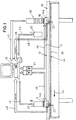
- the device shown in Figures 1-3 of the drawing has a transport path 10 which is connected to a rail 11 a linear motor and two parallel guides 12 is.
- a transport path 10 which is connected to a rail 11 a linear motor and two parallel guides 12 is.
- rails 11 and transport track 10 for example, also in the form of a circle, an ellipse or another shape and as an endless transport track running in a horizontal plane be trained.
- the rail 11 two transport carriages 14a, 14b as movable components assigned to the linear motor, the top of each with at least a receptacle 15 for an object 16 to be printed are provided.
- Structure and mode of operation of a linear motor are familiar to the expert, so that they are not explained in more detail here need to be.
- the invention uses the Linear motor drive as a means of transporting the objects through the at least one printing station and, in particular in If there are several printing stations, also for Bridging the distances between the printing stations and between these and any additional handling, Treatment or control stations.
- Each carriage 14a, 14b has two groove-shaped on the underside Provided recesses 19. In each of these recesses 19th engages one of the guide rails 12, which also between Take up rail 11 and slide 14 transverse forces occurring and cause a precise lateral alignment of the carriage.
- the objects 16 are printed in accordance with the embodiment 1 - 3 by means of the inkjet method.
- This is the Device provided with a central computer 18 which the Nozzles 27 (FIG. 3) of the individual inkjet print heads 20 according to controls a program stored in the computer 18, the Object 16 during the printing process along the transport path 19 is moved.
- Each carriage 14a, 14b has at least one provided a non-contact sensor 22, which with a continuous measuring rail 24 of a length measuring system interacts, which runs parallel to the transport track 10.
- the Measuring rail 24 is with 22 triggering in the sensor Measuring points 26 provided at a very short distance from for example, 1 micron are arranged.
- the basic structure of a printhead results from Fig. 3.
- the nozzles 27, from which the printing ink in drop form ejected in the direction of the object 16 to be decorated are arranged in rows above the object in such a way that the distance between two adjacent nozzles 27 one Row of nozzles 29, 30 is not greater than the maximum Diameter of the drop on the object itself forming paint application.
- the number of rows of nozzles and the Arrangement of the nozzles essentially depends on the quality of the printed image, with the general requirement being that seamless printing, i.e. the application of a closed color order must be possible.
- the actuation of the piezo-electrically controlled, for example Nozzles are frequency controlled, with a specific one Pulse sequence results that the program for that in the respective Corresponds to the printing station to be printed image and with the Speed of the object and thus of the slide at Printing process must be synchronized.
- the speed of the sled is controlled via the Frequency of the three-phase current for the linear motor.
- the relative orientation of the object across its transport direction is in the embodiment shown in the drawing performed so that those nozzles of each row of nozzles 29, 30, etc. effective for the respective printing process placed above the area of the object, the one in the respective printing station I or II Order from printing ink is to be provided.
- This is the arrangement taken so that the length of the rows of nozzles is chosen somewhat larger is defined as the width of each print head printing area or section of the object 16. This means that if the area of the object 16 e.g. B. has the maximum width 38, the length of the rows of nozzles 29, 30, etc. is greater than this maximum width 38.
- Es is then proceeded in such a way that, after having camera 36 and Computer 18 the actual position of the object 16 and thus also the Position of the section to be printed has been determined are those nozzles 27 of the existing nozzle rows for the printing process to be effectively put up above of the section to be printed in the area 38 of the same width are located.
- the section of the nozzle series that has been made effective is designated in Fig. 3 of the drawing with 38a.
- sections 38a, 40 and 41 of the respective New row of nozzles must be set. In the result means this means that the section 38a of the activated nozzles 27 each row depending on the location of the object, thus transversely to the transport direction 34, is shifted to the position of the section of the object to be printed adapt.
- the relative alignment of the object and the printhead in the direction of transport 34 takes place after the actual position has been determined the object and comparing it with the target position by calculating the number of pulses for the in general linearn transport route, the deviation of the actual number of pulses from the target pulse number of the deviation from the actual position of the Object from its target position in the transport direction 34 corresponds.
- the size of the drops of paint applied to the object Points about the size of a diameter of e.g. B. 30 - 50 ⁇ lies.
- the distance between two nozzles in a row should not be larger than the maximum diameter of the point formed by the drop of a nozzle Printing ink.
- the number of parallel rows of nozzles in the direction of transport 34 results from the need in If necessary, a covering (closed) layer of paint on the To form object.
- Variable drop sizes of the printing ink can if necessary be achieved by directly from the same nozzle two or more drops are expelled in succession, where then the speed at which the object is advanced, possibly reduced to zero.
- the decoration process works in such a way that first the respective transport carriage 14a, 14b with the object located on it moves under the camera 36 so that the position of the object is determined.
- the Position of the object within the shot will change after that no longer change, because the object z. B. by negative pressure in the Recording is held.
- the camera 36 can in case of need at the same time also used to carry out an identity check to make sure that the right one Object 16 in the receptacle 15 of the transport carriage 14a or 14b is located.
- the actuation of the linear motor happens via a frequency converter 43, which a line 46 is connected to the respective slide 14, and position and / or speed of the carriage 14a by the measuring rail 24 and sensor 22 having measuring system detected and the computer 18 via an information channel 48 are fed in which the position or speed of the carriage 14a is used for this purpose the movement of the carriage and thus of the object 16 to regulate so that the movement with the expiry of Printing process, that is, the actuation of the nozzles 27 of the Printhead 20, is synchronized and so the desired Print image is created, which is often only a Partial print image will act in the sense that there are two more or more such generally different partial print images, each of which is programmed accordingly Printing station is applied in a specific color, too complete a generally multi-colored overall print image. This means that each printing station normally has its own printing program be assigned.
- the line 46 and the information channel 48 can be part of a Form a control loop through which the speed of the respective transport carriage 14a, 14b in particular during the printing process is kept as constant as possible, so far this with the execution of the print program or the frequency of the Printhead can be matched.
- a variable transport speed during the printing process will be applied when the color density is up the object is changed. This is done via the frequency converter 43, in the energy supply of the transport sled and rail 11 formed linear motor switched on is, the speed of the sled over the frequency of the three-phase current is regulated.
- a separate frequency converter is provided is there is the possibility to transport sled independently to control each other in terms of their speed or to regulate.
- the information channel 44 can be used simultaneously information from the respective print head 20 to the computer To give 18.
- Such information can be, for example, the Relate to the nature of the printing ink, for example their temperature and thus their viscosity etc.
- 1 and 2 is a device with two printing stations shown to which a common transport track 10 is assigned is. This means that after the second partial print image in station II on those carried by the carriage 14b Object has been applied, this carriage 14b initially must be moved in the transport direction 34 to To make room for the slide 14a in the printing station II, so that the object in this slide with the second partial print image can be provided. With multi-color printing more than two printing stations are generally provided be different in all printing stations Colors are applied to the object.
- At least one of the printing stations can be a drying station, not shown in the drawing be provided in which the previously applied Partial print image is dried at least so far that when applying the next partial print image, e.g. B. in the Printing station II, there is no longer a risk that the colors both partial print images run into each other or otherwise mix together.
- the measuring rail 24 only in sections in the Provide areas where the printing stations are located are so that the free distances between the linear transport sections or the printing stations by a usual Means of transport can be overcome.
- it is in general especially when using a larger number of transport sledges in combination with a common one Rail should be appropriate to provide a continuous measuring rail, to the movement of the individual sled over the Check the entire length of the transport path and if necessary to be able to control.
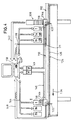
- the exemplary embodiment according to FIGS. 4 and 5 is essentially correct Share with those of the embodiment according to the Fig. 1-3 match, so that for the same or corresponding Share also the same, each by 100 higher reference numerals be used.
- the main difference between the two embodiments is that instead of the inkjet printhead is an ionographic Printhead is used and the pattern of each decoration to be applied first in the form of a charge pattern is applied to the object, then Ink in the form of a toner or other suitable Form with the appropriate electrostatically charged Surface is brought into contact. Because the particles of the Toner or any other printing ink one of a latent Pattern representing charge on the surface of the object have opposite charge, they adhere to the charged Areas of the surface to form the respective decoration which can be a partial decoration. The object with the decoration from the printing ink can undergo further treatment to eliminate unnecessary Ink that is also on the unloaded areas may stick to the surface of the object.
- the transport carriage 114a with the object 116 located thereon under the ionographic Station I printhead 120 is transported, which is generally is referred to as a "cartridge".
- the object 116 can be provided with an electrically conductive layer 162, above which there is a dielectric layer 163, whose surface 160 is provided with the charge pattern.
- the electrically conductive layer 162 is via line 168 grounded.
- the electrically conductive layer 162 which is the base electrode in relation to the print head 120, for example with a CD from its metallized coating be formed, with special measures then being taken must be that the CD in the recording 115 or their metallized layer 162 for the purpose of grounding with the Line 168 is conductively connected. The grounding can of course also take place over the transport carriage 114a or 114b.
- the dielectric layer 163 would then be on the CD metallized layer 162 of the CD can be applied.
- a carrier layer 152 At the bottom of a carrier layer 152 is a number of laterally offset high frequency lines 154 arranged over the entire width of the extend to the printerid area.
- the high-frequency lines are used for the purpose of applying the charge pattern those located below the ionographic print head 136, object 116 carried by the transport carriage 114a with a high-frequency AC voltage, the so-called bursts.
- finger electrodes 156 arranged, which are switched so that they depending on the digital image containing information Enable load carrier program or not. charge carrier with the desired polarity shown in Fig.
- the one located at the bottom of the ionographic print head 136 Screen electrode 164 has the function of being created a stream of only charged particles with the desired polarity by establishing the presence of an electric field, which leads to that only ions with the desired polarity the respective Opening 166 towards the one below decorating object to form a latent charge pattern happen.
- the pair of finger electrodes associated with the left opening 166 156 is on so that a current of Load carriers 158 towards the one below Object 116 flows.
- the two finger electrodes 156 in the Opening 166 on the right are switched off, d. that is, applied with such a low voltage that no Flow of charge particles towards the one below Object 116 flows.
- the arrangement of the openings 166 and thus in pairs arranged finger electrodes 156 of the ionographic Printhead 120 corresponds essentially to the arrangement of the Nozzles 27 of the inkjet print head 20, so that even in the embodiment 4 and 6, for example, the relative Alignment between object and printhead 120 through Appropriate activation of those in question Finger electrodes 156 associated with openings 166 is effected.
- the distances between the openings 126 are also or the associated pair of finger electrodes 156 of the print head 120 dimensioned so that if necessary a charge pattern on the dielectric layer of the Object arises, which is a closed, therefore not interrupted job of printing ink leads.
- the ionographic Print station I After the treatment of the object 116 in the the ionographic Print station I having print head 120 becomes the object 116 carrying carriage 114a in the direction of the arrow 134 transported to station Ia, which is immediate is located behind station I.
- station Ia takes place in the usual way of applying the printing ink, for example in Form of a toner, the particles of which on the surface the charge pattern applied to the object is charged in the opposite direction are so that the particles on the surface 160 of the Object 116 stick as soon as this surface in the previously described Way had been charged.
- the Carriage 114a with the object 116 on it into the next station Ib are transported, in which a facility 170 is arranged, which serves excess Color particles and possibly also on the surface of the object to remove remaining charges.
- station II in which also an ionographic Printhead 120 is present in the previously described Applied a second latent pattern to the object, generally an addition to the first latent pattern or the corresponding print image.
- the station II are the stations IIa and IIb in the direction of transport 134 subordinate by the corresponding to the stations Ia and Ib Treatments are carried out.
Landscapes
- Ink Jet (AREA)
- Duplication Or Marking (AREA)
Abstract
Description
- Fig. 1
- eine Schemadarstellung der wesentlichen Teile einer Vorrichtung zum Dekorieren von Einzelobjekten unter Verwendung eines Inkjet-Kopfes,
- Fig. 2
- die Transportbahn mit dem Linearmotor in perspektivischer Ansicht,
- Fig. 3
- eine Schemadarstellung eines Inkjet-Druckkopfes mit zugeordnetem Objekt,
- Fig. 4
- eine der Fig. 1 entsprechende Darstellung einer zwei ten Ausführungsform, die einen ionografischen Druck kopf verwendet,
- Fig. 5
- eine Schemadarstellung des Aufbaus eines ionografischen Druckkopfes.
Claims (28)
- Verfahren zum Dekorieren eines Objektes (16), bei welchem die Druckfarbe in Abhängigkeit von einem Programm, welches digitalisierte Bildinformationen enthält, aus Düsen (27) punktförmig auf dem von einer Halterung (15) getragenen Objekt aufgebracht wird und einzelne Farbpunkte sich wenigstens zu einem Teildruckbild ergänzen, dadurch gekennzeichnet, daß die das zu bedruckenden Objekt (16) tragende Halterung (15) entlang einer Transportbahn (10) durch wenigstens eine Druckstation (I, II) hindurchbewegt wird, die mit einem die in Abhängigkeit von dem Programm steuerbaren Düsen aufweisenden Druckkopf (20) versehen ist, und wenigstens ein Teil der Düsen (27) während des Transports des Objektes entsprechend dem Programm betätigt wird und die Halterung (15) für das Objekt (16) unter Verwendung eines Linearmotors (11; 14a, 14b) entlang der Transportbahn (10) transportiert wird.
- Verfahren zum Dekorieren eines Objektes (16), bei welchem zunächst in Abhängigkeit von einem Programm, welches digitalisierte Bildinformationen enthält, ein durch elektrostatisch aufgeladene Bereiche auf einer dielektrischen Oberfläche des zu dekorierenden Objektes gebildetes latentes Muster, welches der aufzubringenden Dekoration entspricht, durch Ladungsübertragung hergestellt wird, worauf die Oberfläche mit Farbpartikeln mit entgegengesetzter Ladung in Berührung gebracht wird, um eine dem latenden Ladungsmuster entsprechende Dekoration herzustellen, dadurch gekennzeichnet, daß das zu bedruckende Objekt (116) entlang einer Transportbahn (110) durch wenigstens eine Station (I, II) hindurchbewegt wird, die mit einer in Abhängigkeit von dem Programm steuerbaren ionografischen Druckkopf (120) versehen ist, in welchem mittels Elektroden Ladungsträger (158) erzeugt werden, und ein Strom von Ladungsträgern mit der gewünschten Polarität auf dielektrische Bereiche der Oberfläche (160) des Objektes (116) zur Bildung eines latenten Musters transferiert wird und die Halterung (115) für das Objekt (116) unter Verwendung eines Linearmotors (110; 114a, 114b) entlang der Transportbahn (110) transportiert wird.
- Verfahren nach Anspruch 1 oder 2, dadurch gekennzeichnet, daß das Programm zur Steuerung des Druckkopfes (20; 120) in Abhängigkeit von der Transportbewegung des Objektes (16; 116) abgerufen wird.
- Verfahren nach Anspruch 1 oder 2, dadurch gekennzeichnet, daß die Transportbewegung des Objektes (16; 116) während des Bedruckens in Abhängigkeit vom Ablauf des Programms zur Steuerung des Druckkopfes (20; 120) geregelt wird.
- Verfahren nach Anspruch 1 oder 2, dadurch gekennzeichnet, daß die Halterung (15; 115) von einem Transportschlitten (14a, 14b; 114a, 114b) getragen wird, der Teil des Linearmotors ist.
- Verfahren nach Anspruch 5, dadurch gekennzeichnet, daß die Halterung (15; 115) vom Primärteil des Linearmotors getragen wird.
- Verfahren nach Anspruch 5, dadurch gekennzeichnet, daß die Halterung (15; 115) vom Sekundärteil des Linearmotors getragen wird.
- Verfahren nach Anspruch 1 oder 2, dadurch gekennzeichnet, daß die Elektroden (156) des Druckkopfes (20; 120) quer zur Transportrichtung (34; 134) reihenförmig angeordnet sind und die Düsen (27) bzw. Elektroden (156) wenigstens einer Reihe (29, 30) von Düsen (27) bzw. Elektroden (156) sich über eine Länge erstrecken, die nicht kleiner ist als die Breite (38) des mit der Dekoration zu versehenen Bereiches des Objektes (16; 116) quer zu dessen Transportrichtung (34; 134).
- Verfahren nach Anspruch 1 oder 2, dadurch gekennzeichnet, daß die Lage des auf dem Transportschlitten (14a, 14b; 114a, 114b) befindlichen Objektes (16; 116) erfaßt und die so ermittelte Ist-Position in einem Rechner mit einer gespeicherten Soll-Position verglichen wird und in Abhängigkeit vom Ergebnis dieses Vergleichs der Druckkopf (20; 120) quer zur Transportrichtung (34; 134) des Objektes (16; 116) bewegt wird, um seine bzw. ihre Position an die Ist-Position des Objektes anzupassen.
- Verfahren nach Anspruch 1 oder 2, dadurch gekennzeichnet, daß die Lage des auf dem Transportschlitten befindlichen Objektes (16; 116) erfaßt und die so ermittelte Ist-Position in einem Rechner (18; 118) mit einer gespeicherten Soll-Position verglichen wird und die Länge der wenigstens einen Reihe der Düsen (27) bzw. der Elektroden des Druckkopfes (20; 120) größer ist als die größte Breite (38) des zu dekorierenden Abschnitts des Objektes (16; 116) quer zu dessen Transportrichtung (34; 134) und in Abhängigkeit vom Ergebnis des Vergleiches zwischen Ist-Position und Soll-Position des Objektes jene Düsen (27) bzw. Elektroden (156) der wenigstens einen Reihe (29, 30) von Düesen (27) bzw. Elektroden (156) wirksam gestellt werden, die der jeweiligen Position des Objektes (16; 116) entsprechen.
- Verfahren nach Anspruch 1 oder 2, dadurch gekennzeichnet, daß entlang wenigstens eines Teils der Transportbahn (10; 110) des wenigstens einen Schlittens (14a, 14b; 114a, 114b) ein Längenmeßsystem (24; 124) angeordnet ist, das von einem Sensor (22; 122) gelesen wird, welcher an dem das Objekt tragenden Schlitten (14a, 14b; 114a, 114b) angebracht ist, um so Position und/oder Geschwindigkeit des Schlittens festzustellen.
- Verfahren nach Anspruch 12, dadurch gekennzeichnet, daß durch das inkrementale Längenmeßsystem in dem Sensor (22; 122) Impulse ausgelöst werden, die einem Rechner zugeführt werden.
- Verfahren nach Anspruch 13, dadurch gekennzeichnet, daß der Abstand der die Impulse auslösenden Impulsgeber (26; 126) voneinander im Längenmeßsystem (24; 124) nicht mehr als 1µ beträgt.
- Verfahren nach Anspruch 1, dadurch gekennzeichnet, daß das Objekt (16; 116) aufeinanderfolgend in wenigstens zwei Druckstationen (I, II) bedruckt wird, die in Bewegungsrichtung (34; 134) des Objektes in einem Abstand hintereinander angeordnet sind.
- Verfahren nach Anspruch 2, dadurch gekennzeichnet, daß das Objekt (116) aufeinanderfolgend in wenigstens zwei Stationen (I, II) mit einem Ladungsmuster versehen wird, die in Bewegungsrichtung (134) des Objektes in einem Abstand hintereinander angeordnet sind, und nach jeder Station (I, II) zum Aufbringen eines elektrostatischen Ladungsmusters mit geladenen Farbpartikeln in Berührung gebracht werden.
- Verfahren nach Anspruch 14, dadurch gekennzeichnet, daß die Druckfarbe auf dem Artikel nach Passieren einer Druckstation (I, II) getrocknet wird, bevor der Artikel in einer folgenden Druckstation erneut bedruckt wird.
- Verfahren nach Anspruch 1 oder 2, dadurch gekennzeichnet, daß die Transportbewegungen des das Objekt (16, 116) tragenden wenigstens einen Transportschlittens (14a, 14b; 114a, 114b) zumindest außerhalb der Druckstation (I, II) zumindest teilweise in Abhängigkeit von einem Programm gesteuert werden.
- Vorrichtung zum Dekorieren eines Objektes (16) unter Verwendung eines Verfahrens, bei welchem die Druckfarbe in Abhängigkeit von einem Programm, welches digitalisierte Bildinformationen enthält, aus Düsen (27) punktförmig auf das von einer Halterung (15) getragene Objekt (16) aufgebracht wird und einzelne Punkte sich wenigstens zu einem Teildruckbild ergänzen und wenigstens eine Druckstation (I, II) vorhanden ist, dadurch gekennzeichnet, daß wenigstens eine Transportbahn (10) vorgesehen ist, entlang welcher das von einer Halterung getragene, zu bedruckende Objekt durch die wenigstens eine Druckstation (I, II) transportiert wird, und die wenigstens eine Druckstation (I, II) mit wenigstens einem durch das Programm steuerbaren Druckkopf (20) versehen ist, dessen einzelne Düsen (27) mittels Impulssteuerung entsprechend dem Programm betätigbar sind, und die Vorrichtung mit einem Linearmotor (11; 14a, 14b) für den Transport der Objekte (16) entlang der Transportbahn (10) versehen ist.
- Vorrichtung zum Dekorieren eines Objektes unter Verwendung eines Verfahrens, bei welchem eine dielektrische Oberfläche in Abhängigkeit von einem digitalisierte Bildinformationen enthaltenden Programm mit einer elektrostatischen Ladung versehen versehen wird, welche ein der aufzubringenden Dekoration entsprechendes latentes Muster darstellt, und danach mit Farbpartikeln in Berührung gebracht wird, welche die entgegengesetzte Polarität aufweisen, dadurch gekennzeichnet, daß die Vorrichtung mit wenigstens einer Transportbahn (110) versehen ist, entlang welcher das von einer Halterung (115) getragene zu dekorierende Objekt (116), das mit einer dielektrischen Oberfläche (160) versehen ist, transportiert wird, und die wenigstens eine Station (I, II), in welcher das elektrostatische Ladungsmuster aufgebracht wird, mit wenigstens einem durch das Programm steuerbaren ionografischen Druckkopf (120) zum Erzeugen von Ladungsträgern mit der gewünschten Polarität versehen ist und die Elektroden (156) dieses Druckkopfes (120), durch welchen die Ladungsträger (158) erzeugt werden, in Abhängigkeit vom Programm aktivierbar sind und die Vorrichtung mit einem Linearmotor (111; 114a, 114b) für den Transport der Objekte (116) entlang der Transportbahn (110) versehen ist.
- Vorrichtung nach Anspruch 18 oder 19, dadurch gekennzeichnet, daß die Halterung (15; 115) von einem Schlitten (14a, 14b; 114a, 114b) getragen ist, der das Primärteil des Linearmotors aufweist.
- Vorrichtung nach Anspruch 18 oder 19, dadurch gekennzeichnet, daß die Halterung von einem Schlitten getragen ist, der das Sekundärteil des Linearmotors aufweist.
- Vorrichtung nach Anspruch 18 oder 19, dadurch gekennzeichnet, daß der Druckkopf (20, 120) quer zur Transportbahn (10; 110) bewegbar angeordnet ist, um die Position des Druckkopfes (20, 120) an die Ist-Position des zu bedruckenden Objektes (16; 116) anzupassen.
- Vorrichtung nach Anspruch 18, dadurch gekennzeichnet, daß die Düsen (27) bzw. Elektroden (156) des Druckkopfes (20; 120) in quer zur Transportrichtung (34; 124) des Transportschlittens (14a, 14b; 114a, 114b) verlaufenden Reihen angeordnet sind und die Erstreckung wenigstens einer dieser Reihen (20, 30) größer ist als die Breite (38) des zu bedruckenden Bereiches des Objektes (16 116) quer zu dessen Bewegungsrichtung (34; 134) und in Abhängigkeit von der Ist-Position des Objektes jene Düsen (27) bzw. Elektroden (156) der jeweiligen Reihe (29, 30) von Düsen (27) bzw. Elektroden (156) wirksam gestellt werden, die der jeweiligen Position des zu bedruckenden Bereiches des Objektes entsprechen.
- Vorrichtung nach Anspruch 18 oder 19, dadurch gekennzeichnet, daß entlang wenigstens einem Teilabschnitt der Transportbahn (10; 110) des wenigstens einen Schlittens (14a, 14b; 114a, 114b) des Linearmotors ein Längenmeßsystem (24; 124) angeordnet ist, das von einem Sensor (22; 122) gelesen wird, welcher an dem das Objekt (16; 116) tragenden Schlitten (14a, 14b; 114a, 114b) angebracht ist, um so die Position des Schlittens festzustellen.
- Vorrichtung nach Anspruch 24, dadurch gekennzeichnet, daß der Abstand der im Sensor (22; 122) Impulse auslösenden Geber (26; 126) im Längenmeßsystem (24; 124) weniger als 1µ beträgt.
- Vorrichtung nach Anspruch 18 oder 19, dadurch gekennzeichnet, daß wenigstens zwei Druckstationen (I, II) in einem Abstand in Bewegungsrichtung (34; 134) des Schlittens (14a, 14b; 114a, 114b) hintereinander angeordnet sind.
- Vorrichtung nach Anspruch 18 oder 19, dadurch gekennzeichnet, daß in wenigstens einer Druckstation (I, II) mehrere Reihen (29, 30) von Düsen (27) bzw. Öffnungen (127) in Transportrichtung (34; 134) hintereinander angeordnet sind und die Düsen bzw. Öffnungen der einzelnen Düsenreihen bzw. Öffnungsreihen gegenüber den Düsen bzw. Öffnungen wenigstens einer anderen Reihe quer zur Transportrichtung versetzt angeordnet sind.
- Vorrichtung nach Anspruch 18 oder 19, dadurch gekennzeichnet, daß in Transportrichtung (34; 134) der zu bedruckenden Objekte hinter wenigstens einer Druckstation (I, II) eine Station angeordnet ist, in welcher die auf dem jeweiligen Objekt (16; 116) aufgebrachte Druckfarbe getrocknet wird.
Applications Claiming Priority (2)
| Application Number | Priority Date | Filing Date | Title |
|---|---|---|---|
| DE19946823A DE19946823A1 (de) | 1999-09-30 | 1999-09-30 | Verfahren und Vorrichtung zum Dekorieren von Einzelobjekten |
| DE19946823 | 1999-09-30 |
Publications (3)
| Publication Number | Publication Date |
|---|---|
| EP1088661A2 true EP1088661A2 (de) | 2001-04-04 |
| EP1088661A3 EP1088661A3 (de) | 2001-11-21 |
| EP1088661B1 EP1088661B1 (de) | 2007-08-15 |
Family
ID=7923806
Family Applications (1)
| Application Number | Title | Priority Date | Filing Date |
|---|---|---|---|
| EP00120347A Expired - Lifetime EP1088661B1 (de) | 1999-09-30 | 2000-09-16 | Verfahren und Vorrichtung zum Dekorieren von Einzelobjekten |
Country Status (3)
| Country | Link |
|---|---|
| US (2) | US6478485B1 (de) |
| EP (1) | EP1088661B1 (de) |
| DE (2) | DE19946823A1 (de) |
Cited By (5)
| Publication number | Priority date | Publication date | Assignee | Title |
|---|---|---|---|---|
| EP1857287A2 (de) | 2006-05-17 | 2007-11-21 | Werner Kammann Maschinenfabrik GmbH & Co. KG | Vorrichtung zum Dekorieren von Objekten |
| DE102006038750A1 (de) * | 2006-08-17 | 2008-02-21 | Robert Bürkle GmbH | Vorrichtung zum Bedrucken von starren Werkstücken |
| WO2011069596A1 (de) * | 2009-12-07 | 2011-06-16 | Andrea Mayrhofer | Druckmaschine |
| RU2429135C2 (ru) * | 2006-01-10 | 2011-09-20 | Кхс Аг | Устройство для печатания на бутылках и подобных емкостях |
| FR3009520A1 (fr) * | 2013-08-06 | 2015-02-13 | Dubuit Mach | Machine d'impression a jet d'encre amelioree |
Families Citing this family (14)
| Publication number | Priority date | Publication date | Assignee | Title |
|---|---|---|---|---|
| FR2790421A1 (fr) * | 1999-03-01 | 2000-09-08 | Gemplus Card Int | Machine d'impression graphique pour support de memorisation de type carte, procede d'impression graphique desdits supports de memorisation et supports de memorisation |
| KR100437799B1 (ko) * | 2002-04-08 | 2004-06-30 | 엘지전자 주식회사 | 디스플레이 패널 제작을 위한 잉크젯 얼라인 장치 |
| US6580444B1 (en) * | 2002-04-30 | 2003-06-17 | Alexander V. Drynkin | Thermal printer for compact disks and other media |
| EP2295227A3 (de) * | 2002-12-03 | 2018-04-04 | Stratasys Ltd. | Vorrichtung und Verfahren zum Drucken von drei-dimensionalen Gegenständen |
| US7014284B2 (en) * | 2003-01-16 | 2006-03-21 | Morton William Bill | Ammunition having surface indicia and method of manufacture |
| KR100513771B1 (ko) * | 2003-05-09 | 2005-09-09 | 삼성전자주식회사 | 디스크 프린팅가능한 화상형성장치, 및 화상형성장치용디스크 프린팅장치 |
| US20070019049A1 (en) * | 2005-07-22 | 2007-01-25 | National Pen Corp. | Insert molded print product on demand |
| ATE386642T1 (de) | 2005-12-22 | 2008-03-15 | Tapematic Spa | Tintenstrahldruckapparat und verfahren |
| DE102007014876B4 (de) * | 2007-03-26 | 2010-04-08 | Kba-Metronic Aktiengesellschaft | Transportsystem |
| ITMI20102480A1 (it) | 2010-12-30 | 2012-07-01 | Telecom Italia Spa | Ink-jet printer for printing on cards |
| GB2571343B (en) * | 2018-02-26 | 2021-06-02 | Micropply Ltd | Printing on free surfaces |
| US12116689B2 (en) * | 2021-01-26 | 2024-10-15 | Seagate Technology Llc | Selective screen electroplating |
| TW202243921A (zh) | 2021-02-23 | 2022-11-16 | 瑞士商西克帕控股有限公司 | 用於在卡片上印刷的噴墨印表機 |
| DE102024107362A1 (de) | 2024-03-14 | 2025-09-18 | Giesecke+Devrient ePayments GmbH | Tintenstrahldrucker, Chipkartenbedruckungsanlage, Tintenstrahldruckverfahren und Chipkartenbedruckungsverfahren |
Family Cites Families (44)
| Publication number | Priority date | Publication date | Assignee | Title |
|---|---|---|---|---|
| US3509981A (en) * | 1967-08-07 | 1970-05-05 | Burroughs Corp | Magnetic control apparatus for positioning machine elements to multiple operating positions |
| US3779166A (en) * | 1970-12-28 | 1973-12-18 | Electroprint Inc | Electrostatic printing system and method using ions and toner particles |
| US3900586A (en) * | 1972-12-20 | 1975-08-19 | Australia Res Lab | Electrostatic duplicating process |
| DE2309750B2 (de) | 1973-02-27 | 1976-08-05 | Siemens AG, 1000 Berlin und 8000 München | Vorrichtung zum antrieb von schreiboder druckerwagen in datenschreibern |
| US4081723A (en) | 1975-05-02 | 1978-03-28 | Veb Polygraph Leipzog Kombinat Fur Polygraphische Maschinen Und Ausrustungen | Printing machine |
| US4365549A (en) * | 1978-12-14 | 1982-12-28 | Dennison Manufacturing Company | Electrostatic transfer printing |
| US4463359A (en) * | 1979-04-02 | 1984-07-31 | Canon Kabushiki Kaisha | Droplet generating method and apparatus thereof |
| GB2101931A (en) * | 1981-05-20 | 1983-01-26 | Harrison And Sons | Making a security card |
| JPS61225973A (ja) * | 1985-03-30 | 1986-10-07 | Konishiroku Photo Ind Co Ltd | 多色像形成装置 |
| JPS62117768A (ja) | 1985-11-16 | 1987-05-29 | Konishiroku Photo Ind Co Ltd | レ−ザプリンタの記録媒体の保持部構造 |
| EP0339158A3 (de) | 1988-04-27 | 1991-05-08 | Konica Corporation | Farbbildformungsapparat und -system |
| US4891656A (en) | 1988-12-14 | 1990-01-02 | Delphax Systems | Print cartridge with non-divergent electrostatic field |
| GB2230233A (en) * | 1989-03-02 | 1990-10-17 | Mb Group Plc | An apparatus for, and method of printing on an article having an endless surface |
| US5585900A (en) | 1989-05-15 | 1996-12-17 | Indigo N.V. | Developer for liquid toner imager |
| DE3937020A1 (de) | 1989-11-07 | 1991-05-08 | Du Pont Deutschland | Verfahren und vorrichtung fuer den linearen transport bahn- und blattfoermiger materialien |
| US5204697A (en) | 1990-09-04 | 1993-04-20 | Xerox Corporation | Ionographic functional color printer based on Traveling Cloud Development |
| JPH04148962A (ja) * | 1990-10-12 | 1992-05-21 | Canon Inc | 画像記録装置 |
| US5255058A (en) | 1991-01-22 | 1993-10-19 | Spectrum Sciences B.V. | Liquid developer imaging system using a spaced developing roller and a toner background removal surface |
| US6175422B1 (en) * | 1991-01-31 | 2001-01-16 | Texas Instruments Incorporated | Method and apparatus for the computer-controlled manufacture of three-dimensional objects from computer data |
| US5239318A (en) | 1991-11-15 | 1993-08-24 | Delphax Systems | Finger driver and printer |
| JP3214037B2 (ja) | 1992-02-05 | 2001-10-02 | ソニー株式会社 | 光学ディスクのラベル印刷装置 |
| SG93172A1 (en) | 1993-01-11 | 2002-12-17 | Indigo Nv | Improved latent image development apparatus |
| EP0608879B1 (de) * | 1993-01-29 | 1999-10-27 | Canon Kabushiki Kaisha | Tintenstrahlgerät |
| CA2141646C (en) * | 1994-02-04 | 2001-11-06 | Nobuyuki Kuwabara | Leather coloring process, leather coloring apparatus, and colored leather produced by such process |
| JP3816550B2 (ja) * | 1994-11-07 | 2006-08-30 | キヤノンファインテック株式会社 | プリント媒体搬送装置およびラベルプリンタ |
| DE19532724A1 (de) * | 1995-09-05 | 1997-03-06 | Tampoprint Gmbh | Mehrfarbendruckvorrichtung |
| JP3352879B2 (ja) * | 1995-11-10 | 2002-12-03 | 松下電器産業株式会社 | 画像記録装置、画像データ記録方法およびレンチキュラーシート |
| US5803628A (en) * | 1996-07-01 | 1998-09-08 | Xerox Corporation | Printing apparatus including encoder pending |
| GB9614494D0 (en) | 1996-07-10 | 1996-09-04 | Cookson Matthey Ceramics Plc | Improvements in printing |
| US5947361A (en) | 1996-07-25 | 1999-09-07 | Emo Elektromotorenwerk Kamenz Gmbh | Apparatus for transporting fabrics and web-shaped material with an electric drive device |
| JP3245360B2 (ja) * | 1996-07-30 | 2002-01-15 | キヤノン株式会社 | 画像記録装置 |
| EP0851306B1 (de) | 1996-12-24 | 2000-06-14 | Agfa-Gevaert N.V. | Verfahren für die elektrostatographische Herstellung von Bildmotiven zur Dekoration keramischer Gegenstanden |
| EP0901051A4 (de) * | 1996-12-27 | 2001-05-02 | Kao Corp | Druckverfahren, drucker, drucksachen und optische platte |
| US5915858A (en) * | 1997-03-07 | 1999-06-29 | Eastman Kodak Company | Organizing pixels of different density levels for printing human readable information on CDs |
| US5980011A (en) | 1997-05-16 | 1999-11-09 | Fargo Electronics, Inc. | Identification card printer |
| JPH1134304A (ja) | 1997-07-17 | 1999-02-09 | Canon Inc | 画像記録装置 |
| US6254221B1 (en) * | 1997-12-18 | 2001-07-03 | Lexmark International, Inc. | Printing apparatus with focusing of toner particles |
| US5967676A (en) * | 1998-03-31 | 1999-10-19 | Microtech Conversion Systems, Inc. | Image orientation system for disk printing |
| US6371599B1 (en) * | 1998-04-27 | 2002-04-16 | Minolta Co., Ltd. | Ink jet recording apparatus and drive unit and method for ink jet head |
| US6312123B1 (en) * | 1998-05-01 | 2001-11-06 | L&P Property Management Company | Method and apparatus for UV ink jet printing on fabric and combination printing and quilting thereby |
| US6158346A (en) * | 1998-06-22 | 2000-12-12 | The Penn State Research Foundation | Electronic printing of non-planar macro and micro devices |
| US6364452B1 (en) * | 1999-04-14 | 2002-04-02 | Canon Kabushiki Kaisha | Color printing using multiple inks |
| US6165406A (en) * | 1999-05-27 | 2000-12-26 | Nanotek Instruments, Inc. | 3-D color model making apparatus and process |
| JP3706790B2 (ja) * | 1999-07-05 | 2005-10-19 | キヤノン株式会社 | 非磁性ブラックトナー及び画像形成方法 |
-
1999
- 1999-09-30 DE DE19946823A patent/DE19946823A1/de not_active Withdrawn
- 1999-12-10 US US09/459,233 patent/US6478485B1/en not_active Expired - Lifetime
-
2000
- 2000-09-16 DE DE50014563T patent/DE50014563D1/de not_active Expired - Lifetime
- 2000-09-16 EP EP00120347A patent/EP1088661B1/de not_active Expired - Lifetime
-
2001
- 2001-09-07 US US09/949,115 patent/US6536346B2/en not_active Expired - Fee Related
Cited By (7)
| Publication number | Priority date | Publication date | Assignee | Title |
|---|---|---|---|---|
| RU2429135C2 (ru) * | 2006-01-10 | 2011-09-20 | Кхс Аг | Устройство для печатания на бутылках и подобных емкостях |
| EP1857287A2 (de) | 2006-05-17 | 2007-11-21 | Werner Kammann Maschinenfabrik GmbH & Co. KG | Vorrichtung zum Dekorieren von Objekten |
| DE102006038750A1 (de) * | 2006-08-17 | 2008-02-21 | Robert Bürkle GmbH | Vorrichtung zum Bedrucken von starren Werkstücken |
| WO2011069596A1 (de) * | 2009-12-07 | 2011-06-16 | Andrea Mayrhofer | Druckmaschine |
| FR3009520A1 (fr) * | 2013-08-06 | 2015-02-13 | Dubuit Mach | Machine d'impression a jet d'encre amelioree |
| EP2839965A1 (de) * | 2013-08-06 | 2015-02-25 | Machines Dubuit | Verbesserte Tintenstrahl-Druckmaschine |
| US9527305B2 (en) | 2013-08-06 | 2016-12-27 | Machines Dubuit | Ink jet printing machine |
Also Published As
| Publication number | Publication date |
|---|---|
| EP1088661A3 (de) | 2001-11-21 |
| US6478485B1 (en) | 2002-11-12 |
| DE50014563D1 (de) | 2007-09-27 |
| US20020012556A1 (en) | 2002-01-31 |
| EP1088661B1 (de) | 2007-08-15 |
| US6536346B2 (en) | 2003-03-25 |
| DE19946823A1 (de) | 2001-04-05 |
Similar Documents
| Publication | Publication Date | Title |
|---|---|---|
| EP1088661A2 (de) | Verfahren und Vorrichtung zum Dekorieren von Einzelobjekten | |
| DE60028122T2 (de) | Verbessertes Mehrfarbentampondrucksystem | |
| EP0209896B1 (de) | Verfahren und Vorrichtung zum Dekorieren von Behältern aus Metall oder Kunststoff | |
| EP2705905B1 (de) | Verfahren und Vorrichtung zum Bebildern und/oder Lackieren der Oberfläche von Gegenständen | |
| DE69620404T2 (de) | Vorrichtung und verfahren zum dekorieren von behälter oder ähnliche gegenstände | |
| EP0209531B1 (de) | Verfahren zum tamponschnelldruck | |
| DE2202545B2 (de) | Siebdruckverfahren und -vorrichtung | |
| DE3820340C1 (en) | Pad printing machine | |
| EP1886812A2 (de) | Verfahren und Vorrichtung zur Bedruckung von Einzelobjekten | |
| DE19745136A1 (de) | Rotationsdruckmaschine zum Bedrucken von Bogen | |
| DE2353340A1 (de) | Farbstrahldrucker | |
| DE69304775T2 (de) | Schablonendruckverfahren und Druckvorrichtung mit Plattenherstellung | |
| DE102009061258B3 (de) | Verfahren zum Bedrucken einer nicht-ebenen Oberfläche, sowie Blendenanordnung und Haushaltsgerät | |
| EP0215389B1 (de) | Druck- und Beschriftungsverfahren für Bauteile | |
| EP2065206B1 (de) | Vorrichtung zum Veredeln von Werkstücken | |
| DE102013000835A1 (de) | Digitaltampondruckvorrichtung | |
| DE2328127A1 (de) | Druckvorrichtung fuer alphanumerische schriftzeichen | |
| DE3436688C1 (de) | Verfahren fuer den Mehrfarben-Tampondruck | |
| DE10317283B4 (de) | Tampondruckmaschine | |
| DE102006061893B3 (de) | Vorrichtung zum Aufbringen eines Farbauftrags | |
| DE60009213T2 (de) | Verfahren und Vorrichtung zur Herstellung von dessinierten Papier | |
| DE68906564T2 (de) | Thermo-Drucker. | |
| DE3326453A1 (de) | Druckmaschine | |
| EP0880999B1 (de) | Vorrichtung und Verfahren zur Querbeleimung von Druckprodukten | |
| DE19706295A1 (de) | Verfahren zum Drucken von Mustern |
Legal Events
| Date | Code | Title | Description |
|---|---|---|---|
| PUAI | Public reference made under article 153(3) epc to a published international application that has entered the european phase |
Free format text: ORIGINAL CODE: 0009012 |
|
| AK | Designated contracting states |
Kind code of ref document: A2 Designated state(s): AT BE CH CY DE DK ES FI FR GB GR IE IT LI LU MC NL PT SE Kind code of ref document: A2 Designated state(s): DE |
|
| AX | Request for extension of the european patent |
Free format text: AL;LT;LV;MK;RO;SI |
|
| RIC1 | Information provided on ipc code assigned before grant |
Free format text: 7B 41J 2/01 A, 7G 03G 15/00 B |
|
| PUAL | Search report despatched |
Free format text: ORIGINAL CODE: 0009013 |
|
| AK | Designated contracting states |
Kind code of ref document: A3 Designated state(s): AT BE CH CY DE DK ES FI FR GB GR IE IT LI LU MC NL PT SE |
|
| AX | Request for extension of the european patent |
Free format text: AL;LT;LV;MK;RO;SI |
|
| RIC1 | Information provided on ipc code assigned before grant |
Free format text: 7B 41J 2/01 A, 7G 03G 15/00 B, 7B 41J 2/415 B |
|
| 17P | Request for examination filed |
Effective date: 20020503 |
|
| AKX | Designation fees paid |
Free format text: DE |
|
| 17Q | First examination report despatched |
Effective date: 20050411 |
|
| RAP1 | Party data changed (applicant data changed or rights of an application transferred) |
Owner name: WERNER KAMMANN MASCHINENFABRIK GMBH & CO. KG |
|
| GRAP | Despatch of communication of intention to grant a patent |
Free format text: ORIGINAL CODE: EPIDOSNIGR1 |
|
| GRAS | Grant fee paid |
Free format text: ORIGINAL CODE: EPIDOSNIGR3 |
|
| GRAA | (expected) grant |
Free format text: ORIGINAL CODE: 0009210 |
|
| AK | Designated contracting states |
Kind code of ref document: B1 Designated state(s): DE |
|
| REF | Corresponds to: |
Ref document number: 50014563 Country of ref document: DE Date of ref document: 20070927 Kind code of ref document: P |
|
| PLBE | No opposition filed within time limit |
Free format text: ORIGINAL CODE: 0009261 |
|
| STAA | Information on the status of an ep patent application or granted ep patent |
Free format text: STATUS: NO OPPOSITION FILED WITHIN TIME LIMIT |
|
| 26N | No opposition filed |
Effective date: 20080516 |
|
| PGFP | Annual fee paid to national office [announced via postgrant information from national office to epo] |
Ref country code: DE Payment date: 20101124 Year of fee payment: 11 |
|
| REG | Reference to a national code |
Ref country code: DE Ref legal event code: R081 Ref document number: 50014563 Country of ref document: DE Owner name: KAMMANN MASCHINENBAU GMBH, DE Free format text: FORMER OWNER: WERNER KAMMANN MASCHINENFABRIK GMBH, 32257 BUENDE, DE Effective date: 20110405 |
|
| REG | Reference to a national code |
Ref country code: DE Ref legal event code: R119 Ref document number: 50014563 Country of ref document: DE Effective date: 20120403 |
|
| PG25 | Lapsed in a contracting state [announced via postgrant information from national office to epo] |
Ref country code: DE Free format text: LAPSE BECAUSE OF NON-PAYMENT OF DUE FEES Effective date: 20120403 |