EP0880999B1 - Vorrichtung und Verfahren zur Querbeleimung von Druckprodukten - Google Patents
Vorrichtung und Verfahren zur Querbeleimung von Druckprodukten Download PDFInfo
- Publication number
- EP0880999B1 EP0880999B1 EP98109596A EP98109596A EP0880999B1 EP 0880999 B1 EP0880999 B1 EP 0880999B1 EP 98109596 A EP98109596 A EP 98109596A EP 98109596 A EP98109596 A EP 98109596A EP 0880999 B1 EP0880999 B1 EP 0880999B1
- Authority
- EP
- European Patent Office
- Prior art keywords
- glue
- application means
- set forth
- roller
- nozzles
- Prior art date
- Legal status (The legal status is an assumption and is not a legal conclusion. Google has not performed a legal analysis and makes no representation as to the accuracy of the status listed.)
- Expired - Lifetime
Links
- 238000000034 method Methods 0.000 title claims description 8
- 238000004026 adhesive bonding Methods 0.000 title claims description 7
- 239000003292 glue Substances 0.000 claims description 31
- 238000001816 cooling Methods 0.000 claims description 4
- 239000007921 spray Substances 0.000 claims description 3
- 238000005406 washing Methods 0.000 claims 1
- 238000012423 maintenance Methods 0.000 description 4
- XLYOFNOQVPJJNP-UHFFFAOYSA-N water Substances O XLYOFNOQVPJJNP-UHFFFAOYSA-N 0.000 description 4
- 238000011109 contamination Methods 0.000 description 3
- 238000001035 drying Methods 0.000 description 2
- BDAGIHXWWSANSR-UHFFFAOYSA-M Formate Chemical group [O-]C=O BDAGIHXWWSANSR-UHFFFAOYSA-M 0.000 description 1
- 230000006978 adaptation Effects 0.000 description 1
- 238000004140 cleaning Methods 0.000 description 1
- 238000010276 construction Methods 0.000 description 1
- 238000009434 installation Methods 0.000 description 1
- 238000004519 manufacturing process Methods 0.000 description 1
- 230000013011 mating Effects 0.000 description 1
- 238000004886 process control Methods 0.000 description 1
- 238000005086 pumping Methods 0.000 description 1
- 230000003068 static effect Effects 0.000 description 1
- 230000001360 synchronised effect Effects 0.000 description 1
Images

Classifications
-
- B—PERFORMING OPERATIONS; TRANSPORTING
- B05—SPRAYING OR ATOMISING IN GENERAL; APPLYING FLUENT MATERIALS TO SURFACES, IN GENERAL
- B05C—APPARATUS FOR APPLYING FLUENT MATERIALS TO SURFACES, IN GENERAL
- B05C1/00—Apparatus in which liquid or other fluent material is applied to the surface of the work by contact with a member carrying the liquid or other fluent material, e.g. a porous member loaded with a liquid to be applied as a coating
- B05C1/04—Apparatus in which liquid or other fluent material is applied to the surface of the work by contact with a member carrying the liquid or other fluent material, e.g. a porous member loaded with a liquid to be applied as a coating for applying liquid or other fluent material to work of indefinite length
- B05C1/08—Apparatus in which liquid or other fluent material is applied to the surface of the work by contact with a member carrying the liquid or other fluent material, e.g. a porous member loaded with a liquid to be applied as a coating for applying liquid or other fluent material to work of indefinite length using a roller or other rotating member which contacts the work along a generating line
- B05C1/10—Apparatus in which liquid or other fluent material is applied to the surface of the work by contact with a member carrying the liquid or other fluent material, e.g. a porous member loaded with a liquid to be applied as a coating for applying liquid or other fluent material to work of indefinite length using a roller or other rotating member which contacts the work along a generating line the liquid or other fluent material being supplied from inside the roller
Definitions
- the invention relates to a novel device for transverse gluing of Printed products, in particular in Rollenoffsettmaschinen, and a corresponding method, such as known from EP-A-0 096 832.
- nozzle cross-glue units with individual closures for each a glue applicator known.
- nozzle cross-lapping units are static in terms of moving Printed product, so that because of the mechanical and electrical Tolerances of the application equipment as well as the tear - off behavior of the Glue points only up to limited speeds satisfactory order image can be achieved.
- the object of the invention is a device and a To provide a method for cross gluing printed products, at which a relatively easy maintenance at the same time high Quality of the glue application is guaranteed.
- each component of an application device coming into contact with glue which individually, independently of other applicators, from a roller, e.g. for maintenance purposes, removable or attachable to this.
- glue which individually, independently of other applicators, from a roller, e.g. for maintenance purposes, removable or attachable to this.
- these can be individual nozzles or nozzle heads or nozzle parts.
- At least one interchangeable Holder provided for at least one applicator be. It is also conceivable, on a holder several individual applicators provided. For this reason, on the roller can also be provided replaceable module, which at least two brackets having. By such an arrangement can also be a Cleaning and adaptation to changing requirements easier. As a result, at the same time necessary for such work Shelf life shortened, whereby the machine running time correspondingly advantageous can be extended.
- the flexibility of the arrangement according to the invention can be increased if the applicators can be controlled individually or controlled individually become. As a result, without structural measures, the manner of Glue orders of each individual order device as well as the length of the Glue path be adapted.
- the individual control of the application facilities allows in particular that the applicators can be supplied with glue by a common glue supply, without having to forego the advantages of the invention.
- control may not be too complex, even for a control to be a blockwise or groupwise control of be provided individual applicators.
- the risk of contamination is inventively reduced by the Applicators Glue on the glued printed product squirt.
- This can be done in particular by nozzles. Will the Nozzles electrically controlled, the glue application can be easily to dose exactly.
- the nozzles may also have a pumping device, which transport the glue according to an electrical control. This allows a particularly fine and finely tuned dosage respectively.
- the nozzles bring the glue according to the invention contactless on the printed product.
- a slider this covers accordingly.
- This Slider can be actuated by a pneumatic actuator be.
- a particularly uniform application of the glue takes place when the Applicators substantially synchronous to a movement of the Printed product to be moved. This can especially by be ensured that a the applicators having Roller is rotated at the appropriate speed.
- the device and the process control are particularly designed easy if the roller is formate with respect to the printed product is formed, i. if the circumference of the roller is an integer Multiples of the passage length of the printed product or the Passage length of the printed product an integer multiple of the Roller circumference corresponds. In particular, the circumference of the roller correspond identically to a format of the printed product.
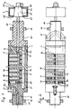
- the roller 1 shown by means of the figures makes it possible to contactlessly To apply glue of different viscosity to a printed product i.e. spray.
- roller 1 The structure and construction of the illustrated roller 1 let the Installation of various nozzles 2 (exemplified) in kind and Number to serve as application facilities. This will be a high Flexibility for the use of the roller 1 achieved.
- the supply of the nozzles 2 with glue is by a common Leimzu Adjust 3 reaches that of a right pin 10 of the roller. 1 reaches to the nozzles 2. From the glue supply 3 are enough individual Supply bores 30 (numbered as an example) right up to the nozzles 2, which in turn with the supply holes 30 through tubes 20 are connected. The connection between the tubes 20 and the Feed holes 30 are made by a plug connection.
- the glue supply 3 has two openings, which by screws 31 and 32 are closed. These openings are used to rinse the Glue feed 3.
- the roller 1 further comprises a cable feed 4, through which electrical control lines of slip rings 40 (numbered as an example) lead to the nozzles 2. For manufacturing reasons, the Cable feed 4 by a screw 33 from the glue feed 3rd separated.
- each of the nozzles 2 is individually over the electrical control lines and the slip rings 40 controlled. It However, a plurality of nozzles 2 to a slip ring 40 and to a Be connected control line.
- a supply terminal 50th intended for pneumatic elements.
- the pneumatics made possible by their air supply and a corresponding air cylinder 51 the Actuation of a slide 5, which is so controlled when the system is at a standstill is that he drying out and sticking the nozzles used. 2 prevented.
- the slider 5 is by a spring 52 in its rest position held.
- the roller 1 is at its pin 10 and 11 by bearings 12 and 13th held and driven by a toothed belt (not shown). Before the glue of the roller 1 is supplied, this is by a cooling. 6 directed.
- the cooling 6 comprises a water reservoir 62, in which O-rings 60 sealed a bushing 61 is arranged. Of the Feedthrough cone 61 is through a mating ring 63 at the water reservoir 62 secured. Through the water reservoir 62 is a constant Water flow passed to ensure a uniform cooling.
- the nozzles 2 are each in recesses 14 (exemplified by) the Roller 1 is arranged. In these recesses 14, the nozzles 2 are through Mounts fastened 7 (exemplified), which in turn at the Roller 1 are attached. As can be seen in particular from FIG. 3, each one has Holder 7 has a central recess 70, in which a corresponding nozzle 2 can be arranged. By means of a in one Hole 71 fastened screw, the nozzle 2 in the holder. 7 be fixed. The holder 7 in turn is through holes 72 as well a threaded hole 73, in each of the corresponding screws can be screwed, attached to the roller 1.
- Each of the holders 7 has an opening 74 at its upper end, through which a respective nozzle 2 can spray glue through.
- the Area of the opening 74 is on the side of the recess 70 in the substantially rectangular, smaller recess 75 is provided, in which the slider 5 is arranged.
- the modular structure allows a simple Adjustment of the roll 1 to Asked requirements.
- Plug connections of the electrical control lines and the glue supply For example, the nozzles 2 can easily be replaced or even simply omitted become.
- the individual electrical control allows that as needed nozzles 2 just can not be operated.
- brackets 7 to a holder or to a Module to connect.
- a module formed by the left side of the roll 11, which with the right side of the roll 10 by a screw 15 (only sketchy shown) is connected.
- the screw 15 can be easily solved and the left side of the roll 11 is replaced by another side of the roll.
Landscapes
- Coating Apparatus (AREA)
- Spray Control Apparatus (AREA)
Description
- Figur 1
- einen Schnitt durch eine erfindungsgemäße Walze,
- Figur 2
- eine Draufsicht auf den Zylinder nach Figur 1,
- Figur 3a
- eine Halterung für eine Düse in der Walze nach Figur 1 im Schnitt mit Blickrichtung entlang des Pfeils A in Figur 3b,
- Figur 3b
- die Halterung in Seitenansicht,
- Figur 3c
- die Halterung im Schnitt mit Blickrichtung entlang des Pfeils C in Figur 3b und
- Figur 3d
- eine Draufsicht auf die Halterung.
Claims (10)
- Vorrichtung zur Querbeleimung von Druckprodukten mit einzelnen Auftragseinrichtungen, die an einer Walze (1) vorgesehen sind, dadurch gekennzeichnet, dass die Auftragseinrichtungen Düsen (2) umfassen, die von dem Druckprodukt beabstandet angeordnet sind.
- Vorrichtung nach Anspruch 1, dadurch gekennzeichnet, dass zumindest eine der Auftragseinrichtungen elektrisch ansteuerbar ist.
- Vorrichtung nach einem der Ansprüche 1 oder 2, dadurch gekennzeichnet, dass an der Walze (1) ein auswechselbares Modul (11) vorgesehen ist, welches wenigstens zwei Halterungen (7) für jeweils zumindest eine Auftragseinrichtung aufweist.
- Vorrichtung nach einem der Ansprüche 1 bis 3, dadurch gekennzeichnet, dass in der Walze (1) eine gemeinsame Leimzufuhr (3) zu den Auftragseinrichtungen vorgesehen ist und zumindest ein Teil der Auftragseinrichtungen in Gruppen ansteuerbar ist.
- Vorrichtung nach einem der Ansprüche 1 bis 4, dadurch gekennzeichnet, dass eine Leimzufuhr (3) vorgesehen ist, die zumindest eine verschlossene Öffnung (31, 32) zum Spülen aufweist.
- Vorrichtung nach einem der Ansprüche 1 bis 5, dadurch gekennzeichnet, dass ein Kühlung (6) für den Leim vorgesehen ist.
- Verfahren zur Querbeleimung von Druckprodukten, bei welchem einzelne Auftragseinrichtungen zumindest in einer Beleimungsposition der Auftragseinrichtungen mit einer im wesentlichen gegen Null gehaltenen Relativgeschwindigkeit zwischen Auftragseinrichtung und Druckprodukt bewegt werden, dadurch gekennzeichnet, dass die Auftragseinrichtungen Leim auf das Druckprodukt spritzen.
- Verfahren nach Anspruch 7, dadurch gekennzeichnet, dass zumindest eine der Auftragseinrichtungen elektrisch angesteuert wird.
- Verfahren nach einem der Ansprüche 7 oder 8, dadurch gekennzeichnet, dass zumindest ein Teil in Gruppen angesteuert wird.
- Verfahren nach einem der Ansprüche 7 bis 9, dadurch gekennzeichnet, dass der Leim gekühlt wird.
Applications Claiming Priority (2)
| Application Number | Priority Date | Filing Date | Title |
|---|---|---|---|
| DE19721996 | 1997-05-27 | ||
| DE19721996 | 1997-05-27 |
Publications (3)
| Publication Number | Publication Date |
|---|---|
| EP0880999A2 EP0880999A2 (de) | 1998-12-02 |
| EP0880999A3 EP0880999A3 (de) | 1998-12-16 |
| EP0880999B1 true EP0880999B1 (de) | 2005-08-03 |
Family
ID=7830538
Family Applications (1)
| Application Number | Title | Priority Date | Filing Date |
|---|---|---|---|
| EP98109596A Expired - Lifetime EP0880999B1 (de) | 1997-05-27 | 1998-05-27 | Vorrichtung und Verfahren zur Querbeleimung von Druckprodukten |
Country Status (3)
| Country | Link |
|---|---|
| EP (1) | EP0880999B1 (de) |
| DE (1) | DE59812971D1 (de) |
| ES (1) | ES2247646T3 (de) |
Families Citing this family (4)
| Publication number | Priority date | Publication date | Assignee | Title |
|---|---|---|---|---|
| DE10054425A1 (de) * | 2000-11-03 | 2002-05-08 | Nordson Corp | Rad-Auftragsvorrichtung zum Auftragen eines Fluids |
| KR101201315B1 (ko) * | 2005-11-28 | 2012-11-14 | 엘지디스플레이 주식회사 | 씨일재 도포 장비 및 그를 이용한 액정표시소자 제조방법 |
| ES2422956B1 (es) * | 2012-03-09 | 2014-07-15 | Tel�sforo GONZ�LEZ OLMOS | Unidad de inyectado de cola fría |
| CN107160853A (zh) * | 2017-06-28 | 2017-09-15 | 太仓市虹鹰印花有限公司 | 一种色彩深度方便调节的印刷辊 |
Family Cites Families (2)
| Publication number | Priority date | Publication date | Assignee | Title |
|---|---|---|---|---|
| DK122580B (da) * | 1970-04-06 | 1972-03-20 | Nordan V Ronneberg H | Påføringsorgan for lim eller til lignende anvendelser. |
| DE3222335C2 (de) * | 1982-06-14 | 1985-01-03 | Planatolwerk W. Hesselmann, Chemische und Maschinenfabrik für Klebetechnik, GmbH & Co KG, 8201 Rohrdorf | Vorrichtung zum Auftragen eines Klebstoffes in Form einer Queranleimung auf eine Bahn |
-
1998
- 1998-05-27 EP EP98109596A patent/EP0880999B1/de not_active Expired - Lifetime
- 1998-05-27 DE DE59812971T patent/DE59812971D1/de not_active Expired - Fee Related
- 1998-05-27 ES ES98109596T patent/ES2247646T3/es not_active Expired - Lifetime
Also Published As
| Publication number | Publication date |
|---|---|
| EP0880999A2 (de) | 1998-12-02 |
| ES2247646T3 (es) | 2006-03-01 |
| DE59812971D1 (de) | 2005-09-08 |
| EP0880999A3 (de) | 1998-12-16 |
Similar Documents
| Publication | Publication Date | Title |
|---|---|---|
| EP2832546B1 (de) | Druckmaschine mit Druckkopfsteuerung | |
| DE69606471T2 (de) | Düsenadapter mit Rezirkulationsventil | |
| DE3636166C2 (de) | ||
| EP0137313A1 (de) | Vorrichtung für Tintenschreibeinrichtungen zum Beschreiben eines Aufzeichnungsträgers | |
| EP3237290B1 (de) | Vorrichtung und verfahren zum etikettieren von einzelnen packungen | |
| DE10302103A1 (de) | Montageeinrichtung für elektronische Bauteile und Montagekopfeinheit für elektronische Bauteile | |
| CH639897A5 (de) | Tintenstrahl-druckvorrichtung. | |
| DE10219129A1 (de) | Verfahren und Vorrichtung zum Drehen und Verteilen oder Zusammenführen von Packs | |
| EP1088661B1 (de) | Verfahren und Vorrichtung zum Dekorieren von Einzelobjekten | |
| DE19935117B4 (de) | Vorrichtung zum Aufbringen von formatmäßigen Klebstoffaufträgen auf eine Übertragungswalze | |
| EP0880999B1 (de) | Vorrichtung und Verfahren zur Querbeleimung von Druckprodukten | |
| DE4307733A1 (de) | Druckmaschine mit auswechselbarem Druckkopf | |
| EP0518083A1 (de) | Bürstenfeuchtwerk in einer Rotationsdruckmaschine | |
| EP0603647A1 (de) | Vorrichtung zum kontinuierlichen Herstellen von Schaumstoffbahnen, insbesondere Hartschaumstoffplatten | |
| EP0995598A1 (de) | Anordnung zum Zuführen von fliessfähiger Druckfarbe zu einem Druckwerk für einen Zigarettenpapierstreifen | |
| EP0442903A1 (de) | Gerät zum bestäuben von druckerzeugnissen. | |
| DE3334444A1 (de) | Siebdruckmaschine | |
| DE4229254A1 (de) | Spritzaggregat für eine Zweikomponentenspritzgießmaschine | |
| AT390570B (de) | Beschichtungsvorrichtung mit luftduesenanordnung | |
| EP0687559A1 (de) | Maschinenanlage mit in Serie angeordneten Druckwerken | |
| DE4425199A1 (de) | Verfahren zum Bedrucken von Wellpappe sowie Einrichtung zur Durchführung des Verfahrens | |
| DE4118697C2 (de) | ||
| DE102023107319B3 (de) | Vorrichtung zur Justage eines Druckkopfes | |
| EP4316670B1 (de) | Anordnung und verfahren zum vorzugsweise automatischen beschichten von gegenständen | |
| EP2578406A2 (de) | Vorrichtung zum Aufbringen von Puder auf Druckbögen |
Legal Events
| Date | Code | Title | Description |
|---|---|---|---|
| PUAI | Public reference made under article 153(3) epc to a published international application that has entered the european phase |
Free format text: ORIGINAL CODE: 0009012 |
|
| PUAL | Search report despatched |
Free format text: ORIGINAL CODE: 0009013 |
|
| AK | Designated contracting states |
Kind code of ref document: A2 Designated state(s): DE ES FR GB IT |
|
| AX | Request for extension of the european patent |
Free format text: AL;LT;LV;MK;RO;SI |
|
| AK | Designated contracting states |
Kind code of ref document: A3 Designated state(s): AT BE CH CY DE DK ES FI FR GB GR IE IT LI LU MC NL PT SE |
|
| AX | Request for extension of the european patent |
Free format text: AL;LT;LV;MK;RO;SI |
|
| 17P | Request for examination filed |
Effective date: 19990609 |
|
| AKX | Designation fees paid |
Free format text: DE ES FR GB IT |
|
| 17Q | First examination report despatched |
Effective date: 20000704 |
|
| GRAP | Despatch of communication of intention to grant a patent |
Free format text: ORIGINAL CODE: EPIDOSNIGR1 |
|
| RTI1 | Title (correction) |
Free format text: DEVICE AD PROCESS FOR TRANSVERSELY GLUING PRINTED PRODUCTS |
|
| RTI1 | Title (correction) |
Free format text: DEVICE AND PROCESS FOR TRANSVERSELY GLUING PRINTED PRODUCTS |
|
| GRAS | Grant fee paid |
Free format text: ORIGINAL CODE: EPIDOSNIGR3 |
|
| GRAA | (expected) grant |
Free format text: ORIGINAL CODE: 0009210 |
|
| AK | Designated contracting states |
Kind code of ref document: B1 Designated state(s): DE ES FR GB IT |
|
| REG | Reference to a national code |
Ref country code: GB Ref legal event code: FG4D Free format text: NOT ENGLISH |
|
| REF | Corresponds to: |
Ref document number: 59812971 Country of ref document: DE Date of ref document: 20050908 Kind code of ref document: P |
|
| GBT | Gb: translation of ep patent filed (gb section 77(6)(a)/1977) | ||
| REG | Reference to a national code |
Ref country code: ES Ref legal event code: FG2A Ref document number: 2247646 Country of ref document: ES Kind code of ref document: T3 |
|
| PGFP | Annual fee paid to national office [announced via postgrant information from national office to epo] |
Ref country code: GB Payment date: 20060424 Year of fee payment: 9 |
|
| ET | Fr: translation filed | ||
| PGFP | Annual fee paid to national office [announced via postgrant information from national office to epo] |
Ref country code: ES Payment date: 20060508 Year of fee payment: 9 |
|
| PLBI | Opposition filed |
Free format text: ORIGINAL CODE: 0009260 |
|
| PGFP | Annual fee paid to national office [announced via postgrant information from national office to epo] |
Ref country code: FR Payment date: 20060518 Year of fee payment: 9 |
|
| PGFP | Annual fee paid to national office [announced via postgrant information from national office to epo] |
Ref country code: IT Payment date: 20060531 Year of fee payment: 9 |
|
| PLAX | Notice of opposition and request to file observation + time limit sent |
Free format text: ORIGINAL CODE: EPIDOSNOBS2 |
|
| 26 | Opposition filed |
Opponent name: HHS LEIMAUFTRAGS-SYSTEME GMBH Effective date: 20060502 |
|
| PGFP | Annual fee paid to national office [announced via postgrant information from national office to epo] |
Ref country code: DE Payment date: 20060630 Year of fee payment: 9 |
|
| PLAF | Information modified related to communication of a notice of opposition and request to file observations + time limit |
Free format text: ORIGINAL CODE: EPIDOSCOBS2 |
|
| GBPC | Gb: european patent ceased through non-payment of renewal fee |
Effective date: 20070527 |
|
| REG | Reference to a national code |
Ref country code: FR Ref legal event code: ST Effective date: 20080131 |
|
| PG25 | Lapsed in a contracting state [announced via postgrant information from national office to epo] |
Ref country code: DE Free format text: LAPSE BECAUSE OF NON-PAYMENT OF DUE FEES Effective date: 20071201 |
|
| PG25 | Lapsed in a contracting state [announced via postgrant information from national office to epo] |
Ref country code: GB Free format text: LAPSE BECAUSE OF NON-PAYMENT OF DUE FEES Effective date: 20070527 |
|
| PG25 | Lapsed in a contracting state [announced via postgrant information from national office to epo] |
Ref country code: FR Free format text: LAPSE BECAUSE OF NON-PAYMENT OF DUE FEES Effective date: 20070531 |
|
| REG | Reference to a national code |
Ref country code: ES Ref legal event code: FD2A Effective date: 20070528 |
|
| PG25 | Lapsed in a contracting state [announced via postgrant information from national office to epo] |
Ref country code: ES Free format text: LAPSE BECAUSE OF NON-PAYMENT OF DUE FEES Effective date: 20070528 |
|
| PG25 | Lapsed in a contracting state [announced via postgrant information from national office to epo] |
Ref country code: IT Free format text: LAPSE BECAUSE OF NON-PAYMENT OF DUE FEES Effective date: 20070527 |
|
| PLBD | Termination of opposition procedure: decision despatched |
Free format text: ORIGINAL CODE: EPIDOSNOPC1 |
|
| PLBM | Termination of opposition procedure: date of legal effect published |
Free format text: ORIGINAL CODE: 0009276 |
|
| STAA | Information on the status of an ep patent application or granted ep patent |
Free format text: STATUS: OPPOSITION PROCEDURE CLOSED |
|
| 27C | Opposition proceedings terminated |
Effective date: 20100215 |