EP1083359A2 - Aerodynamisches Radlagergehäuse - Google Patents
Aerodynamisches Radlagergehäuse Download PDFInfo
- Publication number
- EP1083359A2 EP1083359A2 EP00117889A EP00117889A EP1083359A2 EP 1083359 A2 EP1083359 A2 EP 1083359A2 EP 00117889 A EP00117889 A EP 00117889A EP 00117889 A EP00117889 A EP 00117889A EP 1083359 A2 EP1083359 A2 EP 1083359A2
- Authority
- EP
- European Patent Office
- Prior art keywords
- bearing housing
- wheel bearing
- wheel
- air
- guiding
- Prior art date
- Legal status (The legal status is an assumption and is not a legal conclusion. Google has not performed a legal analysis and makes no representation as to the accuracy of the status listed.)
- Granted
Links
Images



Classifications
-
- F—MECHANICAL ENGINEERING; LIGHTING; HEATING; WEAPONS; BLASTING
- F16—ENGINEERING ELEMENTS AND UNITS; GENERAL MEASURES FOR PRODUCING AND MAINTAINING EFFECTIVE FUNCTIONING OF MACHINES OR INSTALLATIONS; THERMAL INSULATION IN GENERAL
- F16D—COUPLINGS FOR TRANSMITTING ROTATION; CLUTCHES; BRAKES
- F16D55/00—Brakes with substantially-radial braking surfaces pressed together in axial direction, e.g. disc brakes
- F16D55/02—Brakes with substantially-radial braking surfaces pressed together in axial direction, e.g. disc brakes with axially-movable discs or pads pressed against axially-located rotating members
- F16D55/22—Brakes with substantially-radial braking surfaces pressed together in axial direction, e.g. disc brakes with axially-movable discs or pads pressed against axially-located rotating members by clamping an axially-located rotating disc between movable braking members, e.g. movable brake discs or brake pads
-
- B—PERFORMING OPERATIONS; TRANSPORTING
- B60—VEHICLES IN GENERAL
- B60T—VEHICLE BRAKE CONTROL SYSTEMS OR PARTS THEREOF; BRAKE CONTROL SYSTEMS OR PARTS THEREOF, IN GENERAL; ARRANGEMENT OF BRAKING ELEMENTS ON VEHICLES IN GENERAL; PORTABLE DEVICES FOR PREVENTING UNWANTED MOVEMENT OF VEHICLES; VEHICLE MODIFICATIONS TO FACILITATE COOLING OF BRAKES
- B60T1/00—Arrangements of braking elements, i.e. of those parts where braking effect occurs specially for vehicles
- B60T1/02—Arrangements of braking elements, i.e. of those parts where braking effect occurs specially for vehicles acting by retarding wheels
- B60T1/06—Arrangements of braking elements, i.e. of those parts where braking effect occurs specially for vehicles acting by retarding wheels acting otherwise than on tread, e.g. employing rim, drum, disc, or transmission or on double wheels
- B60T1/065—Arrangements of braking elements, i.e. of those parts where braking effect occurs specially for vehicles acting by retarding wheels acting otherwise than on tread, e.g. employing rim, drum, disc, or transmission or on double wheels employing disc
-
- F—MECHANICAL ENGINEERING; LIGHTING; HEATING; WEAPONS; BLASTING
- F16—ENGINEERING ELEMENTS AND UNITS; GENERAL MEASURES FOR PRODUCING AND MAINTAINING EFFECTIVE FUNCTIONING OF MACHINES OR INSTALLATIONS; THERMAL INSULATION IN GENERAL
- F16D—COUPLINGS FOR TRANSMITTING ROTATION; CLUTCHES; BRAKES
- F16D65/00—Parts or details
- F16D65/78—Features relating to cooling
- F16D65/84—Features relating to cooling for disc brakes
- F16D65/847—Features relating to cooling for disc brakes with open cooling system, e.g. cooled by air
-
- B—PERFORMING OPERATIONS; TRANSPORTING
- B60—VEHICLES IN GENERAL
- B60G—VEHICLE SUSPENSION ARRANGEMENTS
- B60G2200/00—Indexing codes relating to suspension types
- B60G2200/10—Independent suspensions
- B60G2200/14—Independent suspensions with lateral arms
- B60G2200/142—Independent suspensions with lateral arms with a single lateral arm, e.g. MacPherson type
-
- B—PERFORMING OPERATIONS; TRANSPORTING
- B60—VEHICLES IN GENERAL
- B60G—VEHICLE SUSPENSION ARRANGEMENTS
- B60G2204/00—Indexing codes related to suspensions per se or to auxiliary parts
- B60G2204/10—Mounting of suspension elements
- B60G2204/12—Mounting of springs or dampers
- B60G2204/129—Damper mount on wheel suspension or knuckle
-
- B—PERFORMING OPERATIONS; TRANSPORTING
- B60—VEHICLES IN GENERAL
- B60G—VEHICLE SUSPENSION ARRANGEMENTS
- B60G2206/00—Indexing codes related to the manufacturing of suspensions: constructional features, the materials used, procedures or tools
- B60G2206/01—Constructional features of suspension elements, e.g. arms, dampers, springs
- B60G2206/50—Constructional features of wheel supports or knuckles, e.g. steering knuckles, spindle attachments
-
- B—PERFORMING OPERATIONS; TRANSPORTING
- B60—VEHICLES IN GENERAL
- B60G—VEHICLE SUSPENSION ARRANGEMENTS
- B60G2206/00—Indexing codes related to the manufacturing of suspensions: constructional features, the materials used, procedures or tools
- B60G2206/01—Constructional features of suspension elements, e.g. arms, dampers, springs
- B60G2206/70—Materials used in suspensions
- B60G2206/71—Light weight materials
- B60G2206/7102—Aluminium alloys
-
- B—PERFORMING OPERATIONS; TRANSPORTING
- B60—VEHICLES IN GENERAL
- B60G—VEHICLE SUSPENSION ARRANGEMENTS
- B60G2206/00—Indexing codes related to the manufacturing of suspensions: constructional features, the materials used, procedures or tools
- B60G2206/01—Constructional features of suspension elements, e.g. arms, dampers, springs
- B60G2206/80—Manufacturing procedures
- B60G2206/81—Shaping
- B60G2206/8101—Shaping by casting
Definitions
- the invention relates to a wheel bearing housing for guiding a wheel of a vehicle according to the Preamble of claim 1.
- Wheel bearing housings on vehicles are generally used to connect a wheel to one Vehicle body and for guiding the wheel.
- bearings provided for a drive shaft.
- a guide link for a vehicle wheel is known, in which the The guide link is hollow.
- the handlebar cavity has two openings.
- the the first opening is arranged near a braking device which is located radially inside the wheel.
- a second opening is oriented in the direction of travel, so that the wind blows through the hollow Wheel control arm is guided on the brake.
- this arrangement be in connection with a Wishbones are used, so should be a scoop-shaped deflection surface at the inlet opening be provided to steer the airstream in the direction of the inlet opening.
- a disadvantage of this known solution is the complex manufacture of the cavity.
- the formations on the wheel bearing housing as a means of connection to a Vehicle bodies are provided, in some areas to form a wall of the air guiding element to use. This measure allows the cross-section and guide length of the Air guide element are further enlarged.
- the formations are specifically proposed curved and designed so that they lead away from the wheel at their starting point, i.e. in the Usually lie across the direction of travel.
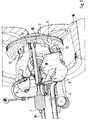
- the wheel bearing housing 1 shown in FIGS. 1 and 2 is on a front axle of a motor vehicle arranged. Inside a wheel 16 there is an internally ventilated brake disc 2 as a braking device arranged, which cooperates with a brake caliper 3 attached to the wheel bearing housing 1. With a Vehicle body, not shown, is the wheel bearing housing 1 via a wishbone 4, a trailing arm 5 and a receptacle 6 for a shock absorber pivotally connected. A tie rod 7 is used Adjustment of the pivot position of the wheel bearing housing 1 in relation to the vehicle body. A Drive shaft 19 is held in a central opening 8 of the wheel bearing housing and drives the wheel 16 on.
- a guide vane 9 is held on the trailing arm 5, the front end of which is approximately in the direction of travel F extends and the rear end 17 points in the direction of the brake disc 2.
- Such a vane is already known for example from DE 38 03 801 A1.
- the wheel bearing housing 1 is in an area pointing in the direction of travel F as an air guiding element educated.
- the wheel bearing housing 1 is adjacent to an area 10 Surface area on a cylindrical base housing 11 no further projections are provided. This results in between an inner edge of the brake disc 2 and the cylindrical base housing 11 the annular area 10 through which air to the inside of the brake disc 2 to there lying supply openings of the internal ventilation of the brake disc 2 can reach.
- the guide vane 9 is arranged so that it directs air flowing from the direction of travel F into the region 10.
- the cylindrical base element 11 therefore acts as an air guide element in the extension of the guide vane 9.
- a molded part 12 on the wheel bearing housing 1 for connection to the tie rod 7 is provided, so shaped that it is at its attachment point 15 on the wheel bearing housing 1 (see. Fig. 5) first across the direction of travel F, i.e. away from the wheel 16, then extends in an arc 14 to guide a pivot point 13 for the tie rod 7.
- the inside of the formed by the sheet 14 Formation 12 forms a continuation of that formed by the cylindrical basic housing 11 Air guiding element and a boundary of the area 10.
- FIG. 2 shows the wheel bearing housing 1 essentially inside-front.
- Fig. 3 shows a plan view of the wheel bearing housing 1 together with the brake disc 2 and the Brake caliper 3.
- the area 10 on one side of the brake disc 2 and on the other side is limited by the curvature 14 of the formation 12, clearly visible.
- FIG. 4 shows a side view of the wheel bearing housing 1 in the installed state, with a wheel 16 and the brake disc 2 in the area facing the direction of travel F for better illustration were cut open. It is clearly visible that the rear edge 17 of the guide vane 9 immediately cylindrical basic housing 11 is facing. One arranged on the top of the guide vane 9 Guide element 18 is also aligned so that part of the coming from the guide vane 9 Air flow is introduced into the curvature 14. In the interaction between the guide vane 9 and the Outside of the wheel bearing housing 1, here the one formed from the basic housing 11 and the molding 12 Area 10, the area 10 is thus flowed over its entire cross section. This carries on to improve the air supply to the brake disc, because now the inside of the air channels via a larger rotation angle and thus be supplied with fresh cooling air over a longer period of time.
- Fig. 5 shows the wheel bearing housing alone in a side view according to Fig. 4.
Landscapes
- Engineering & Computer Science (AREA)
- General Engineering & Computer Science (AREA)
- Mechanical Engineering (AREA)
- Transportation (AREA)
- Braking Arrangements (AREA)
- Steering-Linkage Mechanisms And Four-Wheel Steering (AREA)
- Vehicle Body Suspensions (AREA)
Abstract
Description
Es zeigen
- Fig. 1
- eine Übersicht über ein erfindungsgemäßes Radlagergehäuse im eingebauten Zustand,
- Fig. 2
- die Darstellung nach Fig. 1, jedoch aus einem anderen Blickwinkel,
- Fig. 3
- eine Draufsicht auf das Radlagergehäuse im eingebauten Zustand,
- Fig. 4
- eine Seitenansicht des Radlagergehäuses im eingebauten Zustand mit Aufbrüchen,
- Fig. 5
- das Radlagergehäuse nach Fig. 1, jedoch ohne Anbauteile, und
- Fig. 6
- das Radlagergehäuse nach Fig. 4, jedoch ohne Anbauteile
Claims (5)
- Radlagergehäuse (1) zur Führung eines Rades (16) eines Fahrzeuges, wobei das am Radlagergehäuse gelagertes Rad mit einer Bremseinrichtung (2) versehen ist, dadurch gekennzeichnet, daß die Außenseite des Gehäuses zumindest bereichsweise als Luftführungslelement (11,14) ausgebildet ist.
- Radlagergehäuse nach Anspruch 1, dadurch gekennzeichnet, daß das Luftführungselement (11,14) ein offener Kanal ist.
- Radlagergehäuse nach Anspruch 1 oder 2, dadurch gekennzeichnet, daß zur Verbindung mit einem Fahrzeugaufbau am Gehäuse Anformungen (12) vorgesehen sind, die bereichsweise zur Bildung einer Wandung (14) des Luftführungselementes verwendet sind.
- Radlagergehäuse nach Anspruch 3, dadurch gekennzeichnet, daß die Anformungen (12) eine gewölbte Form aufweisen und an ihrem Ansatzpunkt (15) vom Rad (16) wegführend gestaltet sind.
- Radlagergehäuse nach Anspruch 4, dadurch gekennzeichnet, daß an einem Radlenker (5) eine Leitschaufel (9) angeordnet ist, die einen Luftstrom in Richtung des Luftführungslelementes (11,14) am Radlagergehäuse (1) lenkt.
Applications Claiming Priority (2)
| Application Number | Priority Date | Filing Date | Title |
|---|---|---|---|
| DE19943536A DE19943536C1 (de) | 1999-09-11 | 1999-09-11 | Aerodynamisches Radlagergehäuse |
| DE19943536 | 1999-09-11 |
Publications (3)
| Publication Number | Publication Date |
|---|---|
| EP1083359A2 true EP1083359A2 (de) | 2001-03-14 |
| EP1083359A3 EP1083359A3 (de) | 2003-11-19 |
| EP1083359B1 EP1083359B1 (de) | 2007-05-23 |
Family
ID=7921649
Family Applications (1)
| Application Number | Title | Priority Date | Filing Date |
|---|---|---|---|
| EP00117889A Expired - Lifetime EP1083359B1 (de) | 1999-09-11 | 2000-08-19 | Aerodynamisches Radlagergehäuse |
Country Status (5)
| Country | Link |
|---|---|
| US (1) | US6357562B1 (de) |
| EP (1) | EP1083359B1 (de) |
| JP (1) | JP4546628B2 (de) |
| DE (2) | DE19943536C1 (de) |
| ES (1) | ES2283259T3 (de) |
Cited By (1)
| Publication number | Priority date | Publication date | Assignee | Title |
|---|---|---|---|---|
| EP1688330A1 (de) * | 2005-02-04 | 2006-08-09 | Dr.Ing. h.c.F. Porsche Aktiengesellschaft | Luftleitvorrichtung an einer Vorderachse bzw. Hinterachse eines Kraftfahrzeugs |
Families Citing this family (7)
| Publication number | Priority date | Publication date | Assignee | Title |
|---|---|---|---|---|
| US7198139B2 (en) * | 2004-01-05 | 2007-04-03 | Honda Motor Co., Ltd. | Air guide for cooling a vehicle brake assembly |
| JP2006213107A (ja) * | 2005-02-02 | 2006-08-17 | Yamaha Motor Co Ltd | 鞍乗り型車両 |
| JP5304207B2 (ja) * | 2008-12-08 | 2013-10-02 | 日産自動車株式会社 | ブレーキエアガイド構造 |
| DE102013223668A1 (de) * | 2013-11-20 | 2015-05-21 | Bayerische Motoren Werke Aktiengesellschaft | Kühlluftführung für eine Reibbelagbremse eines Kraftfahrzeugs |
| DE102018205793B4 (de) | 2018-04-17 | 2024-11-14 | Audi Ag | Radträgeranordnung mit einem Luftleitelement für ein Kraftfahrzeug |
| DE102020111517A1 (de) | 2020-04-28 | 2021-10-28 | Dr. Ing. H.C. F. Porsche Aktiengesellschaft | Radträgeranordnung einer Vorderachse bzw. Hinterachse eines Kraftfahrzeuges |
| FR3125747B1 (fr) * | 2021-07-28 | 2024-04-12 | Renault Sas | Bras ou triangle de suspension et procédé de fabrication d’un tel bras ou triangle de suspension |
Citations (2)
| Publication number | Priority date | Publication date | Assignee | Title |
|---|---|---|---|---|
| DE2830450A1 (de) | 1977-07-11 | 1979-02-15 | Citroen Sa | Aufhaengelenker |
| DE3803801A1 (de) | 1988-02-09 | 1989-08-17 | Porsche Ag | Luftleitvorrichtung fuer radbremsen eines kraftfahrzeugs |
Family Cites Families (14)
| Publication number | Priority date | Publication date | Assignee | Title |
|---|---|---|---|---|
| DE2748195C3 (de) * | 1977-10-27 | 1981-01-15 | Hermann Dr.-Ing. 2000 Norderstedt Klaue | Luftgekühlte Vollbelag-Scheibenbremse |
| JPS55115635A (en) * | 1979-02-24 | 1980-09-05 | Toyota Motor Corp | Disk brake |
| JPS55142133A (en) * | 1979-04-24 | 1980-11-06 | Toyota Motor Corp | Dust cover for disc brake |
| JPS57929A (en) * | 1980-06-03 | 1982-01-06 | Akebono Brake Ind Co Ltd | Dust cover for disc brake |
| JPS6227716Y2 (de) * | 1980-11-29 | 1987-07-16 | ||
| DE3120021C2 (de) * | 1981-05-20 | 1987-07-09 | Daimler-Benz Ag, 7000 Stuttgart | Anordnung zur Radkühlung an Kraftfahrzeugen |
| DE3608317C2 (de) * | 1986-03-13 | 1995-03-23 | Teves Gmbh Alfred | Teilbelag-Scheibenbremse, insbesondere für Kraftfahrzeuge |
| DE3630334A1 (de) * | 1986-09-05 | 1988-03-10 | Porsche Ag | Vorrichtung zum zufuehren von kuehlluft zu einer bremsscheibe |
| DE8802975U1 (de) * | 1988-03-05 | 1988-04-28 | Dr.Ing.H.C. F. Porsche Ag, 7000 Stuttgart | Luftleitvorrichtung zum Kühlen von Radbremsen |
| JPH04169309A (ja) * | 1990-10-31 | 1992-06-17 | Nissan Motor Co Ltd | 車両用ブレーキ装置の冷却機構 |
| JP2808941B2 (ja) * | 1991-10-03 | 1998-10-08 | トヨタ自動車株式会社 | ディスクブレーキ用エアガイド |
| JPH07251722A (ja) * | 1994-03-15 | 1995-10-03 | Nissan Motor Co Ltd | 車両のブレーキ冷却装置 |
| DE4431247C1 (de) * | 1994-09-02 | 1995-12-21 | Daimler Benz Ag | Befestigungsanordnung eines Leitungshalters an einem Radführungsglied eines gebremsten Rades |
| FR2798624B1 (fr) * | 1999-09-22 | 2001-11-23 | Peugeot Citroen Automobiles Sa | Dispositif de suspension perfectionne pour une roue avant de vehicule automobile |
-
1999
- 1999-09-11 DE DE19943536A patent/DE19943536C1/de not_active Expired - Fee Related
-
2000
- 2000-08-19 ES ES00117889T patent/ES2283259T3/es not_active Expired - Lifetime
- 2000-08-19 DE DE50014339T patent/DE50014339D1/de not_active Expired - Lifetime
- 2000-08-19 EP EP00117889A patent/EP1083359B1/de not_active Expired - Lifetime
- 2000-09-07 JP JP2000272067A patent/JP4546628B2/ja not_active Expired - Fee Related
- 2000-09-11 US US09/659,064 patent/US6357562B1/en not_active Expired - Fee Related
Patent Citations (2)
| Publication number | Priority date | Publication date | Assignee | Title |
|---|---|---|---|---|
| DE2830450A1 (de) | 1977-07-11 | 1979-02-15 | Citroen Sa | Aufhaengelenker |
| DE3803801A1 (de) | 1988-02-09 | 1989-08-17 | Porsche Ag | Luftleitvorrichtung fuer radbremsen eines kraftfahrzeugs |
Cited By (1)
| Publication number | Priority date | Publication date | Assignee | Title |
|---|---|---|---|---|
| EP1688330A1 (de) * | 2005-02-04 | 2006-08-09 | Dr.Ing. h.c.F. Porsche Aktiengesellschaft | Luftleitvorrichtung an einer Vorderachse bzw. Hinterachse eines Kraftfahrzeugs |
Also Published As
| Publication number | Publication date |
|---|---|
| DE50014339D1 (de) | 2007-07-05 |
| DE19943536C1 (de) | 2001-04-05 |
| EP1083359B1 (de) | 2007-05-23 |
| EP1083359A3 (de) | 2003-11-19 |
| JP4546628B2 (ja) | 2010-09-15 |
| US6357562B1 (en) | 2002-03-19 |
| ES2283259T3 (es) | 2007-11-01 |
| JP2001116073A (ja) | 2001-04-27 |
Similar Documents
| Publication | Publication Date | Title |
|---|---|---|
| DE69613505T2 (de) | Vorrichtung zum Verringern des Fahrwiderstandes von Fahrzeugen | |
| DE102011053350B4 (de) | Luftströmungs-Ablenkeinrichtung für Fahrzeuge | |
| DE3412916C2 (de) | Lüfterflügel | |
| DE60205977T2 (de) | Turbinenschaufel mit Kühlluftleiteinrichtung | |
| EP1319526A2 (de) | Fahrzeugrad oder Felge | |
| EP0853562A1 (de) | Wischblatt für eine scheibenwischvorrichtung eines fahrzeuges | |
| DE19727685C2 (de) | Luftleiteinrichtung | |
| WO2014170398A1 (de) | Kraftfahrzeug-motorkühlung-lüfterzarge mit staudruckklappen | |
| EP0888957B1 (de) | Vorrichtung zur Belüftung eines Aggregates an einem Fahrzeug | |
| EP3169577A1 (de) | Fahrzeug mit einer luftleitvorrichtung | |
| DE19943536C1 (de) | Aerodynamisches Radlagergehäuse | |
| EP3544880B1 (de) | Luftleitvorrichtung zur verwendung an der unterseite eines kraftfahrzeugs | |
| DE102020006425A1 (de) | Vorrichtung zur Kühlung mindestens einer Radbremse eines Fahrzeugs | |
| DE3410296A1 (de) | Vorrichtung zur verbesserung der bodenhaftung von fahrzeugen | |
| DE2616948C3 (de) | Geschwindigkeitsabhängiger Spoiler | |
| DE20122871U1 (de) | Rad für Fahrzeuge | |
| DE102016215032A1 (de) | Luftleiteinrichtung für ein Kraftfahrzeug | |
| DE2830450C3 (de) | Führungslenker für ein Fahrzeugrad | |
| DE2632168A1 (de) | Kraftfahrzeug, insbesondere lastkraftwagen | |
| DE3632033C2 (de) | Luftleitvorrichtung für ein Vollheck-Kraftfahrzeug | |
| DE3437855A1 (de) | Bereifbares rad fuer fahrzeuge | |
| WO2006131180A1 (de) | Gepäckbehälter für ein motorrad | |
| DE102016203199A1 (de) | Radlaufanordnung für ein Rad, Kraftfahrzeug mit einer Radlaufanordnung | |
| DE2935635A1 (de) | Frontspoileranordnung | |
| DE10351248B4 (de) | Vorrichtung zum Beeinflussen der Luftströmung bei einem öffnungsfähigen Fahrzeugdach |
Legal Events
| Date | Code | Title | Description |
|---|---|---|---|
| PUAI | Public reference made under article 153(3) epc to a published international application that has entered the european phase |
Free format text: ORIGINAL CODE: 0009012 |
|
| AK | Designated contracting states |
Kind code of ref document: A2 Designated state(s): AT BE CH CY DE DK ES FI FR GB GR IE IT LI LU MC NL PT SE |
|
| AX | Request for extension of the european patent |
Free format text: AL;LT;LV;MK;RO;SI |
|
| PUAL | Search report despatched |
Free format text: ORIGINAL CODE: 0009013 |
|
| AK | Designated contracting states |
Kind code of ref document: A3 Designated state(s): AT BE CH CY DE DK ES FI FR GB GR IE IT LI LU MC NL PT SE |
|
| AX | Request for extension of the european patent |
Extension state: AL LT LV MK RO SI |
|
| RIC1 | Information provided on ipc code assigned before grant |
Ipc: 7B 60T 1/06 B Ipc: 7F 16D 65/847 A Ipc: 7B 60B 35/00 B Ipc: 7B 60T 5/00 B Ipc: 7F 16D 55/224 B |
|
| 17P | Request for examination filed |
Effective date: 20040519 |
|
| AKX | Designation fees paid |
Designated state(s): DE ES FR GB IT |
|
| GRAP | Despatch of communication of intention to grant a patent |
Free format text: ORIGINAL CODE: EPIDOSNIGR1 |
|
| GRAS | Grant fee paid |
Free format text: ORIGINAL CODE: EPIDOSNIGR3 |
|
| GRAA | (expected) grant |
Free format text: ORIGINAL CODE: 0009210 |
|
| AK | Designated contracting states |
Kind code of ref document: B1 Designated state(s): DE ES FR GB IT |
|
| REG | Reference to a national code |
Ref country code: GB Ref legal event code: FG4D Free format text: NOT ENGLISH |
|
| REF | Corresponds to: |
Ref document number: 50014339 Country of ref document: DE Date of ref document: 20070705 Kind code of ref document: P |
|
| PGFP | Annual fee paid to national office [announced via postgrant information from national office to epo] |
Ref country code: ES Payment date: 20070830 Year of fee payment: 8 |
|
| GBT | Gb: translation of ep patent filed (gb section 77(6)(a)/1977) |
Effective date: 20070809 |
|
| ET | Fr: translation filed | ||
| REG | Reference to a national code |
Ref country code: ES Ref legal event code: FG2A Ref document number: 2283259 Country of ref document: ES Kind code of ref document: T3 |
|
| PLBE | No opposition filed within time limit |
Free format text: ORIGINAL CODE: 0009261 |
|
| STAA | Information on the status of an ep patent application or granted ep patent |
Free format text: STATUS: NO OPPOSITION FILED WITHIN TIME LIMIT |
|
| 26N | No opposition filed |
Effective date: 20080226 |
|
| REG | Reference to a national code |
Ref country code: FR Ref legal event code: TP |
|
| REG | Reference to a national code |
Ref country code: ES Ref legal event code: FD2A Effective date: 20080820 |
|
| REG | Reference to a national code |
Ref country code: FR Ref legal event code: CD |
|
| PG25 | Lapsed in a contracting state [announced via postgrant information from national office to epo] |
Ref country code: ES Free format text: LAPSE BECAUSE OF NON-PAYMENT OF DUE FEES Effective date: 20080820 |
|
| REG | Reference to a national code |
Ref country code: FR Ref legal event code: TP |
|
| REG | Reference to a national code |
Ref country code: GB Ref legal event code: 732E Free format text: REGISTERED BETWEEN 20110310 AND 20110316 |
|
| REG | Reference to a national code |
Ref country code: GB Ref legal event code: 732E Free format text: REGISTERED BETWEEN 20110331 AND 20110406 |
|
| PGFP | Annual fee paid to national office [announced via postgrant information from national office to epo] |
Ref country code: GB Payment date: 20110819 Year of fee payment: 12 Ref country code: FR Payment date: 20110901 Year of fee payment: 12 |
|
| PGFP | Annual fee paid to national office [announced via postgrant information from national office to epo] |
Ref country code: IT Payment date: 20110825 Year of fee payment: 12 |
|
| GBPC | Gb: european patent ceased through non-payment of renewal fee |
Effective date: 20120819 |
|
| REG | Reference to a national code |
Ref country code: FR Ref legal event code: ST Effective date: 20130430 |
|
| PG25 | Lapsed in a contracting state [announced via postgrant information from national office to epo] |
Ref country code: IT Free format text: LAPSE BECAUSE OF NON-PAYMENT OF DUE FEES Effective date: 20120819 |
|
| PG25 | Lapsed in a contracting state [announced via postgrant information from national office to epo] |
Ref country code: GB Free format text: LAPSE BECAUSE OF NON-PAYMENT OF DUE FEES Effective date: 20120819 |
|
| PG25 | Lapsed in a contracting state [announced via postgrant information from national office to epo] |
Ref country code: FR Free format text: LAPSE BECAUSE OF NON-PAYMENT OF DUE FEES Effective date: 20120831 |
|
| PGFP | Annual fee paid to national office [announced via postgrant information from national office to epo] |
Ref country code: DE Payment date: 20150807 Year of fee payment: 16 |
|
| REG | Reference to a national code |
Ref country code: DE Ref legal event code: R119 Ref document number: 50014339 Country of ref document: DE |
|
| PG25 | Lapsed in a contracting state [announced via postgrant information from national office to epo] |
Ref country code: DE Free format text: LAPSE BECAUSE OF NON-PAYMENT OF DUE FEES Effective date: 20170301 |