EP1082775B1 - Accumulateur au plomb de performances ameliorees - Google Patents
Accumulateur au plomb de performances ameliorees Download PDFInfo
- Publication number
- EP1082775B1 EP1082775B1 EP99920875A EP99920875A EP1082775B1 EP 1082775 B1 EP1082775 B1 EP 1082775B1 EP 99920875 A EP99920875 A EP 99920875A EP 99920875 A EP99920875 A EP 99920875A EP 1082775 B1 EP1082775 B1 EP 1082775B1
- Authority
- EP
- European Patent Office
- Prior art keywords
- active material
- electrode
- positive electrode
- negative electrode
- battery according
- Prior art date
- Legal status (The legal status is an assumption and is not a legal conclusion. Google has not performed a legal analysis and makes no representation as to the accuracy of the status listed.)
- Expired - Lifetime
Links
Images


Classifications
-
- H—ELECTRICITY
- H01—ELECTRIC ELEMENTS
- H01M—PROCESSES OR MEANS, e.g. BATTERIES, FOR THE DIRECT CONVERSION OF CHEMICAL ENERGY INTO ELECTRICAL ENERGY
- H01M10/00—Secondary cells; Manufacture thereof
- H01M10/04—Construction or manufacture in general
- H01M10/0413—Large-sized flat cells or batteries for motive or stationary systems with plate-like electrodes
-
- H—ELECTRICITY
- H01—ELECTRIC ELEMENTS
- H01M—PROCESSES OR MEANS, e.g. BATTERIES, FOR THE DIRECT CONVERSION OF CHEMICAL ENERGY INTO ELECTRICAL ENERGY
- H01M10/00—Secondary cells; Manufacture thereof
- H01M10/04—Construction or manufacture in general
- H01M10/0468—Compression means for stacks of electrodes and separators
-
- H—ELECTRICITY
- H01—ELECTRIC ELEMENTS
- H01M—PROCESSES OR MEANS, e.g. BATTERIES, FOR THE DIRECT CONVERSION OF CHEMICAL ENERGY INTO ELECTRICAL ENERGY
- H01M10/00—Secondary cells; Manufacture thereof
- H01M10/06—Lead-acid accumulators
-
- H—ELECTRICITY
- H01—ELECTRIC ELEMENTS
- H01M—PROCESSES OR MEANS, e.g. BATTERIES, FOR THE DIRECT CONVERSION OF CHEMICAL ENERGY INTO ELECTRICAL ENERGY
- H01M4/00—Electrodes
- H01M4/02—Electrodes composed of, or comprising, active material
- H01M4/14—Electrodes for lead-acid accumulators
-
- H—ELECTRICITY
- H01—ELECTRIC ELEMENTS
- H01M—PROCESSES OR MEANS, e.g. BATTERIES, FOR THE DIRECT CONVERSION OF CHEMICAL ENERGY INTO ELECTRICAL ENERGY
- H01M4/00—Electrodes
- H01M4/02—Electrodes composed of, or comprising, active material
- H01M4/62—Selection of inactive substances as ingredients for active masses, e.g. binders, fillers
-
- H—ELECTRICITY
- H01—ELECTRIC ELEMENTS
- H01M—PROCESSES OR MEANS, e.g. BATTERIES, FOR THE DIRECT CONVERSION OF CHEMICAL ENERGY INTO ELECTRICAL ENERGY
- H01M10/00—Secondary cells; Manufacture thereof
- H01M10/42—Methods or arrangements for servicing or maintenance of secondary cells or secondary half-cells
- H01M10/44—Methods for charging or discharging
- H01M10/446—Initial charging measures
-
- H—ELECTRICITY
- H01—ELECTRIC ELEMENTS
- H01M—PROCESSES OR MEANS, e.g. BATTERIES, FOR THE DIRECT CONVERSION OF CHEMICAL ENERGY INTO ELECTRICAL ENERGY
- H01M10/00—Secondary cells; Manufacture thereof
- H01M10/42—Methods or arrangements for servicing or maintenance of secondary cells or secondary half-cells
- H01M2010/4292—Aspects relating to capacity ratio of electrodes/electrolyte or anode/cathode
-
- Y—GENERAL TAGGING OF NEW TECHNOLOGICAL DEVELOPMENTS; GENERAL TAGGING OF CROSS-SECTIONAL TECHNOLOGIES SPANNING OVER SEVERAL SECTIONS OF THE IPC; TECHNICAL SUBJECTS COVERED BY FORMER USPC CROSS-REFERENCE ART COLLECTIONS [XRACs] AND DIGESTS
- Y02—TECHNOLOGIES OR APPLICATIONS FOR MITIGATION OR ADAPTATION AGAINST CLIMATE CHANGE
- Y02E—REDUCTION OF GREENHOUSE GAS [GHG] EMISSIONS, RELATED TO ENERGY GENERATION, TRANSMISSION OR DISTRIBUTION
- Y02E60/00—Enabling technologies; Technologies with a potential or indirect contribution to GHG emissions mitigation
- Y02E60/10—Energy storage using batteries
-
- Y—GENERAL TAGGING OF NEW TECHNOLOGICAL DEVELOPMENTS; GENERAL TAGGING OF CROSS-SECTIONAL TECHNOLOGIES SPANNING OVER SEVERAL SECTIONS OF THE IPC; TECHNICAL SUBJECTS COVERED BY FORMER USPC CROSS-REFERENCE ART COLLECTIONS [XRACs] AND DIGESTS
- Y02—TECHNOLOGIES OR APPLICATIONS FOR MITIGATION OR ADAPTATION AGAINST CLIMATE CHANGE
- Y02P—CLIMATE CHANGE MITIGATION TECHNOLOGIES IN THE PRODUCTION OR PROCESSING OF GOODS
- Y02P70/00—Climate change mitigation technologies in the production process for final industrial or consumer products
- Y02P70/50—Manufacturing or production processes characterised by the final manufactured product
Definitions
- the invention relates to accumulators lead with improved performance by compared to current lead-acid batteries.
- Batteries of this type are intended in particular for the production of batteries efficient, for example for vehicles electric.
- the mass energy of the accumulators lead for electric vehicles is 30 to 40 Wh / kg. On vehicles, these orders of magnitude are reduced by 20%. Also, to the discharge regimes in 1 to 2 hours, the lead accumulator is revealed twice less efficient than the nickel-cadmium accumulator, and three times less than the sodium-sulfur accumulator.
- the rate should be increased of use of the active materials of the electrodes.
- research avenues can be considered for achieve this result.
- One of them concerns the collection of charges on the active materials side electrode.
- the other concerns better distribution of reagents within the electrodes.
- the active material of the electrodes is only very partially used, even during of a so-called full discharge, the percentage of transformed material being of the order of 25 to 30%.
- the exchange of electrons between the material active and the external circuit are ensured by lead alloyed conductors in the form of grids or combs.
- the dimensions of these collectors are determined by the following two factors: constitute the mechanical support of the electrodes, and the need to resist corrosion phenomena to which they are subjected within the electrodes. In consequence, in today's mounting technology, so-called monopolar, the mass of collectors represents 40 to 50% of the mass of the electrodes for applications in electric vehicles.
- the amount of sulfuric acid is largely less than the amount of active ingredient likely to be oxidized or reduced. Their report is around 15%. To this acid, present on site, are added to the during a discharge of contributions by diffusion from the exterior of the plates, all the more significant that the discharge is slower. Usage rates active ingredients are highest in the vicinity of the surface of the plates. They can reach 60 to 70%, compared to the average value of 25 to 30% for the complete electrode.
- the present invention has precisely for subject a lead accumulator of the type described in documents [1] to [3], which presents a mass energy improved thanks to provisions allowing increase the utilization rate of active materials electrodes with better distribution reagents within the electrodes.
- This quantity of sulfuric acid in the positive or negative electrode can represent for example from 0.20 to 1 mole, or from 0.20 to 0.70 mole of H 2 SO 4 per mole of the active material of the electrode.
- the quantity of sulfuric acid in the positive electrode represents at least 0.25 and better still 0.40 mole of H 2 SO 4 per mole active material of the positive electrode
- the amount of sulfuric acid in the negative electrode represents at least 0.25 and better still 0.40 mole of H 2 SO 4 per mole of active material of the electrode negative.
- the porosity of the positive electrode and / or that of the negative electrode is modified.
- an active electrode material is used having an apparent density in the dry charged state of 2.8 to 3.2 g / cm 3 , preferably 3.0 to 3.2 g / cm 3 .
- Increasing the porosity of the material active the positive electrode and / or the electrode negative increases the amount of acid sulfuric per mole of active material and promote thus the exchanges between the active electrode material and the electrolyte.
- the active material of the electrodes is obtained from a paste of lead oxide, water and sulfuric acid, by pasting a grid serving as a current collector, followed by drying, then d '' ripening for 48 hours in an atmosphere saturated with water vapor. Then, by applying an electric current, on the electrodes, lead dioxide PbO 2 serving as active material for the positive electrode and spongy metallic lead serving as active material for the negative electrode.
- the water and acid content of the lead oxide paste regulates the porosity of the active material obtained subsequently. According to the invention, it is therefore sufficient to adjust the water and acid content of the dough to obtain an active material having an apparent density situated in the range mentioned above.
- Another means of increasing the porosity of the active material of an electrode according to the prior art is to subject this electrode which comprises a material generally having an apparent density in the dry charged state of 3.3 to 3 , 6 g / cm 3 , to an electrical treatment consisting of at least one deep discharge followed by recharging.
- the structure of the electrode is modified positive and / or negative electrode by adding inert porous particles capable of charging of electrolyte in the active material of these electrodes.
- porous particles can be fragments microporous of inert material such as polyethylene, polypropylene or other polymers resistant to the electrolyte. The presence of electrolyte in these porous particles thus increases the amount of electrolyte per mole of active material of the electrode.
- porous particles can be added to the lead oxide paste used for the pasting of grids or current collectors.
- the amount of electrolyte per mole of active material of the electrodes is adjusted by increasing the density of the electrolyte.
- an H 2 SO 4 solution having a density of at least 1.30, for example from 1.30 to 1.50 and preferably from 1.32 to 1.40, can be used.
- this third mode of realization is combined with one of the two modes of previous achievements.
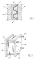
- Figure 1 is a schematic view in vertical section of a lead accumulator in which improvements of the invention may be used.
- Figure 2 is a perspective view of the positive and negative electrode assembly of the Figure 1 with application of pressure to the assembly.
- Figure 3 is a perspective view of a embodiment of the positive electrode of the Figure 1 arranged in a microporous separator.
- Figure 4 illustrates the evolution of the radius of medium pore of the active material of positive electrodes of accumulators according to the number of cycles, in the case where the electrode is subjected to a stress (curve 1) and in the case where there is no constraint (curve 2).
- FIG. 5 represents the evolution of the capacity (in Ah) of an accumulator under stress as a function of the number of cycles when one carries out several deep discharges of the electrodes between the 530 th and the 750 th cycle.
- Figure 6 illustrates the improvement achieved by increasing the ratio of quantity of electrolyte to amount of active material, by forced circulation electrolyte.
- a lead accumulator comprising a positive electrode 1 in the form of a plate and a negative electrode 3 in plate shape separated from each other by a assembly comprising a corrugated spacer element 5 and perforated, made for example of polyvinyl chloride PVC, and an element 7 such as a fibrous veil produced for example in glass fibers.
- Positive electrodes and negative are immersed in an electrolyte 9.
- the positive electrode consists of lead oxide PbO 2 covering a sheet of cellular lead or grid.
- the negative electrode 3 is similarly made from lead foam.
- the positive electrode 1 is also separated from the electrolyte 9 by an element microporous 11 which can be constituted by the product called Darak®, made of paper pulp, glass wool and phenolic resin.
- an element microporous 11 which can be constituted by the product called Darak®, made of paper pulp, glass wool and phenolic resin.
- Figure 2 there is illustrated the accumulator of Figure 1, supplemented by the means to apply a constraint to the whole perpendicular to the plane of electrodes 1 and 3.
- the assembly 12 is disposed between two flanges 13 and 15 which are connected to each other by a set of threaded rods 17 provided with bolts 19 and calibrated springs 20.
- FIG 3 there is shown in perspective the positive electrode 1 surrounded by microporous separator 11.
- this separator completely surrounds the electrode and is made up of two microporous separators welded at their periphery, by example by a bead of hot-melt resin 12.
- the separator assembly formed by spacer element 5 and element 7 can be replaced by a single element consisting of a fiber mattress of glass.
- curve 1 there is shown the evolution of the mean pore radius (in ⁇ m) of the active material of a positive electrode under stress depending on the number of cycles performed.
- curve 2 the evolution of mean pore radius of a similar electrode used in an accumulator without application of constraint.
- the average pore radius increases throughout from cycling to the end of life (around 800 cycles).
- the positive electrodes are generally prepared from a lead oxide paste which covers sheets of cellular lead or grids serving as a support. After the grates have been pasted, they are dried and left to mature for 48 hours in an atmosphere saturated with water vapor. The active material PbO 2 is then formed by application of an electric current. The active material of the negative electrodes is prepared in the same way, but when the electric current is applied, the lead oxide paste is reduced to lead foam.
- porosity is obtained higher of these active materials using a higher water and acid content of the dough.
- Capacities are measured during so-called control cycles, identical to the previous except that for the load, the second level under 2A is extended by 2 h, and that the discharge under 11A is extended until the voltage across the the accumulator reaches 1.70 V.
- the cycling defined above is again practiced.
- the objective is to analyze, in the absence of deep discharge, the sustainability or not of the capacity increase. After 250 cycles, that is to say at the 1000 th cycle, the measured capacity is always greater than the nominal capacity. The decrease seems linear. The slope is 5.5 Ah for 100 cycles.
- the lead is transformed into lead sulfate according to the following reaction scheme: Pb + SO 4 ⁇ PbSO 4 .
- the lead sulphate produced has a higher volume than lead oxide or lead original.
- Another possibility to increase the porosity of the active material of each of the electrodes is to include porous elements in it, by example of porous particles incorporated into the paste lead oxide used in the manufacture of the electrode.
- Usable porous particles can be made up of polyethylene particles the smallest dimension of which is not more than 0.5 mm, preferably about 0.2 mm.
- porous particles representing 2 to 50%, preferably 5 to 30% of the final volume of the electrode material. These particles may have a porosity of 60 to 70% by volume, which allows to include in the active material a quantity additional electrolyte.
- a lead accumulator conforms to reference [1] having a capacity of 26 A.h with an electrolyte of density 1.28 sees this capacity increase to 30 A.h with an electrolyte of density 1.32 and at 45 A.h with an electrolyte of density 1.32 after six deep discharges.
- FIG. 6 the effect has been illustrated. beneficial from an increased amount of electrolyte per mole active material.
- This figure 6 represents the evolution of the transformation rate (in%) of active material of the positive electrode depending on the discharge current (in amperes) for an accumulator at lead conforming to reference [1] (curve 41) and for a similar lead-acid battery (curve 43) in which we favored the exchanges between the electrolyte and the active material by carrying out a circulation forced electrolyte through the active material to a speed of 2 ⁇ m / s, which corresponds to a quantity increased electrolyte per mole of active material.
- the electrolyte used which consists of more or less dilute sulfuric acid, can be in gelled form, for example by means of SiO 2 , or in absorbed form in a suitable material which can be a glass microfibres mat acting as a spreader or a microporous separator such as those represented in 5 and 11 in FIG. 1.
- the positive electrode and the negative electrode of the accumulator are associated together to form bipolar plates having on one side the active electrode material positive and on the other side the active material negative electrode.
- any bipolar wall leads to a significant improvement in mass power for short power calls.
- mass energy in particular with the regimes of discharge in 1 to 2 hours which characterize the operation of electric vehicles.
- the electrodes, pressed against the wall bipolar offer only one side to the electrolyte, which reduces the contribution of species by a factor of 2 reactive from the electrolyte outside the electrodes.
Landscapes
- Chemical & Material Sciences (AREA)
- Chemical Kinetics & Catalysis (AREA)
- Electrochemistry (AREA)
- General Chemical & Material Sciences (AREA)
- Engineering & Computer Science (AREA)
- Manufacturing & Machinery (AREA)
- Battery Electrode And Active Subsutance (AREA)
- Secondary Cells (AREA)
Description
- une électrode positive comportant de l'oxyde de plomb comme matériau actif,
- une électrode négative comportant de la mousse de plomb comme matériau actif,
- un électrolyte constitué par une solution d'acide sulfurique,
- un élément séparateur entre l'électrode positive et l'électrode négative, et
- des moyens pour appliquer une contrainte à l'ensemble perpendiculairement au plan des électrodes,
- 1) modifier la structure de l'électrode positive afin d'augmenter la quantité d'acide sulfurique dans l'électrode positive,
- 2) modifier la structure de l'électrode négative afin d'augmenter la quantité d'acide sulfurique dans l'électrode négative, et
- 3) augmenter la concentration en H2SO4 de l'électrolyte.
- l'augmentation de la concentration en H2SO4 de l'électrolyte,
- l'augmentation de porosité des électrodes, et
- l'inclusion d'éléments poreux dans ces électrodes.
- décharge sous courant constant (11A) pendant 3 h, et
- charge sous courant constant en deux paliers :
- 1er palier : 6,65 A pendant 5h, et
- 2ème palier : 2 A pendant 4h.
- décharge sous courant réduit jusqu'à chute de la tension à moins de 1 V par élément de l'accumulateur, pouvant aller jusqu'au court-circuit imposé pendant 60 h,
- succession de cycles comportant une décharge complète alors que jusqu'au 530ème cycle la décharge était interrompue au bout de 3 heures.
Claims (13)
- Accumulateur au plomb comprenant :une électrode positive (1) comportant de l'oxyde de plomb comme matériau actif,une électrode négative (3) comportant de la mousse de plomb comme matériau actif,un électrolyte (9) constitué par une solution d'acide sulfurique,un élément séparateur (5,7) entre l'électrode positive et l'électrode négative, etdes moyens pour appliquer une contrainte à l'ensemble perpendiculairement au plan des électrodes, dans lequel, à l'état chargé, la quantité d'acide sulfurique dans l'électrode positive représente au moins 0,20 mole de H2SO4 par mole du matériau actif de l'électrode positive, et/ou la quantité d'acide sulfurique dans l'électrode négative représente au moins 0,20 mole de H2SO4 par mole du matériau actif de l'électrode négative, et dans lequel la contrainte appliquée aux électrodes est de 0,01 à 0,3 MPa.
- Accumulateur selon la revendication 1, dans lequel, à l'état chargé, la quantité d'acide sulfurique dans l'électrode positive représente au moins 0,25 mol de H2SO4 par mole du matériau actif de l'électrode positive, et/ou la quantité d'acide sulfurique dans l'électrode négative représente au moins 0,25 mole de H2SO4 par mole de matériau actif de l'électrode négative.
- Accumulateur selon la revendication 1 ou 2, dans lequel le matériau actif de l'électrode positive a une densité apparente à l'état chargé sec de 2,8 à 3,2 g/cm3.
- Accumulateur selon l'une quelconque des revendications 1 à 3, dans lequel le matériau actif de l'électrode négative a une densité apparente à l'état chargé sec de 2,8 à 3,2 g/cm3.
- Accumulateur selon l'une quelconque des revendications 1, 2 et 4, dans lequel on utilise une électrode positive dont le matériau actif a une densité apparente à l'état chargé sec de 3,3 à 3,6 g/cm3 et à laquelle on fait subir au moins une décharge profonde suivie d'une recharge pour amener sa densité apparente à l'état chargé sec à une valeur de 2,8 à 3,2 g/cm3.
- Accumulateur selon l'une quelconque des revendications 1 à 3, dans lequel on utilise une électrode négative dont le matériau actif a une densité apparente, à l'état chargé sec, de 3,3 à 3,6 g/cm3 et à laquelle on fait subir au moins une décharge profonde suivie d'une recharge pour amener sa densité apparente à l'état chargé sec à une valeur de 2,8 à 3,2 g/cm3.
- Accumulateur au plomb selon l'une quelconque des revendications 1 à 6, dans lequel le matériau actif de l'électrode positive et/ou le matériau actif de l'électrode négative comprennent en outre des particules poreuses inertes capables de se charger d'électrolyte.
- Accumulateur selon la revendication 7, dans lequel les particules poreuses sont en polyéthylène.
- Accumulateur selon l'une quelconque des revendications 7 et 8, dans lequel la quantité de particules poreuses représente 5 à 80 % du volume final du matériau de l'électrode.
- Accumulateur selon la revendication 7 ou 8, dans lequel la quantité de particules poreuses représente 10 à 50 % du volume final du matériau de l'électrode.
- Accumulateur selon l'une quelconque des revendications 1 à 10, dans lequel on utilise comme électrolyte une solution d'acide sulfurique ayant une densité d'au moins 1,30.
- Accumulateur selon la revendication 11, dans lequel la densité de la solution d'acide sulfurique est de 1,30 à 1,50, de préférence de 1,32 à 1,40.
- Accumulateur selon l'une quelconque des revendications 1 à 12, dans lequel l'électrode positive et l'électrode négative sont associées entre elles pour former des plaques bipolaires comportant sur une face le matériau actif d'électrode positive et sur l'autre face le matériau actif d'électrode négative.
Applications Claiming Priority (3)
| Application Number | Priority Date | Filing Date | Title |
|---|---|---|---|
| FR9805509 | 1998-04-30 | ||
| FR9805509A FR2778270B1 (fr) | 1998-04-30 | 1998-04-30 | Accumulateur au plomb de performances ameliorees |
| PCT/FR1999/001022 WO1999057782A1 (fr) | 1998-04-30 | 1999-04-29 | Accumulateur au plomb de performances ameliorees |
Publications (2)
| Publication Number | Publication Date |
|---|---|
| EP1082775A1 EP1082775A1 (fr) | 2001-03-14 |
| EP1082775B1 true EP1082775B1 (fr) | 2002-02-20 |
Family
ID=9525917
Family Applications (1)
| Application Number | Title | Priority Date | Filing Date |
|---|---|---|---|
| EP99920875A Expired - Lifetime EP1082775B1 (fr) | 1998-04-30 | 1999-04-29 | Accumulateur au plomb de performances ameliorees |
Country Status (6)
| Country | Link |
|---|---|
| US (1) | US6458489B1 (fr) |
| EP (1) | EP1082775B1 (fr) |
| JP (1) | JP4949553B2 (fr) |
| DE (1) | DE69900913T2 (fr) |
| FR (1) | FR2778270B1 (fr) |
| WO (1) | WO1999057782A1 (fr) |
Families Citing this family (9)
| Publication number | Priority date | Publication date | Assignee | Title |
|---|---|---|---|---|
| CN100346504C (zh) * | 2002-02-07 | 2007-10-31 | Kvg技术股份有限公司 | 由吸收性网筛、电解质的过滤作用及吸收性网筛形成的具有凝胶电解质的铅蓄电池 |
| US6853547B2 (en) * | 2002-12-16 | 2005-02-08 | Axxion Group Corporation | Computer drive mounting device and method |
| ATE416489T1 (de) * | 2003-02-03 | 2008-12-15 | Kelly Shawn P | Verfahren und seine vorrichtung zur effizienzverbesserung und zum verhindern der zersetzung dieser energiespeichervorrichtung |
| US7705558B2 (en) * | 2003-10-31 | 2010-04-27 | Denovo Research, Llc | In situ rechargeable battery and charging stand |
| JP4274256B2 (ja) | 2006-08-25 | 2009-06-03 | トヨタ自動車株式会社 | 蓄電装置用電極及び蓄電装置 |
| JP5471307B2 (ja) * | 2009-10-29 | 2014-04-16 | 日本ゼオン株式会社 | 電気化学素子用電極の製造方法、電気化学素子用電極及び電気化学素子 |
| WO2013022439A1 (fr) * | 2011-08-09 | 2013-02-14 | Depoo Paul | Bec verseur libérable pour accéder sélectivement à l'eau de coco à l'intérieur d'une noix de coco |
| EP2638585A4 (fr) * | 2010-11-10 | 2016-10-12 | Epic Ventures Inc | Accumulateur au plomb comprenant des matières actives maintenues dans une structure réticulaire |
| CN103311586A (zh) * | 2013-05-16 | 2013-09-18 | 吉林泰格节能产品科技开发有限公司 | 一种铅酸蓄电池修复还原剂 |
Family Cites Families (28)
| Publication number | Priority date | Publication date | Assignee | Title |
|---|---|---|---|---|
| FR2425733A1 (fr) * | 1978-05-10 | 1979-12-07 | Electricite De France | Element d'accumulateur au plomb perfectionne et batterie d'accumulateurs formee de ces elements, notamment pour traction |
| FR2438346A1 (fr) | 1978-10-04 | 1980-04-30 | Anvar | Perfectionnement aux elements d'accumulateur au plomb |
| JPS5569970A (en) * | 1978-11-22 | 1980-05-27 | Japan Storage Battery Co Ltd | Enclosed type lead storage battery |
| JPS56143668A (en) * | 1980-04-09 | 1981-11-09 | Japan Storage Battery Co Ltd | Lead acid battery |
| US4548835A (en) * | 1981-07-16 | 1985-10-22 | Matsushita Electric Industrial Company, Limited | Method for fabricating electrodes for use in lead storage batteries |
| JPS5864772A (ja) * | 1981-10-09 | 1983-04-18 | Japan Storage Battery Co Ltd | パワ−用鉛蓄電池 |
| JPS58212077A (ja) * | 1982-06-02 | 1983-12-09 | Matsushita Electric Ind Co Ltd | 密閉式鉛蓄電池 |
| JPS60207264A (ja) * | 1984-03-30 | 1985-10-18 | Japan Storage Battery Co Ltd | 小形密閉鉛蓄電池 |
| JPS6145565A (ja) * | 1984-08-09 | 1986-03-05 | Yuasa Battery Co Ltd | 蓄電池 |
| DE3532697A1 (de) * | 1985-09-13 | 1987-04-02 | Deta Akkumulatoren | Akkumulator |
| JPS62249354A (ja) * | 1986-03-26 | 1987-10-30 | Japan Storage Battery Co Ltd | 高比重電解液を用いた鉛蓄電池 |
| JPH01128367A (ja) * | 1987-11-11 | 1989-05-22 | Yuasa Battery Co Ltd | 密閉形鉛蓄電池 |
| JPH01220371A (ja) * | 1988-02-29 | 1989-09-04 | Furukawa Battery Co Ltd:The | 鉛蓄電池用クラッド式極板 |
| JP2712400B2 (ja) * | 1988-10-19 | 1998-02-10 | 松下電器産業株式会社 | 鉛蓄電池 |
| JP2847761B2 (ja) * | 1989-06-12 | 1999-01-20 | 株式会社ユアサコーポレーション | 密閉形鉛蓄電池及びその製造方法 |
| JP3185300B2 (ja) * | 1991-12-02 | 2001-07-09 | 日本電池株式会社 | 密閉形鉛蓄電池 |
| JP3366037B2 (ja) * | 1992-12-25 | 2003-01-14 | 松下電器産業株式会社 | シール型鉛電池 |
| US5344727A (en) * | 1993-06-21 | 1994-09-06 | General Motors Corporation | Bipolar battery electrode |
| JPH0945365A (ja) * | 1995-07-31 | 1997-02-14 | Matsushita Electric Ind Co Ltd | 鉛蓄電池 |
| JPH09115518A (ja) * | 1995-10-20 | 1997-05-02 | Shin Kobe Electric Mach Co Ltd | 鉛蓄電池用正極板 |
| JPH09167628A (ja) * | 1995-12-14 | 1997-06-24 | Yuasa Corp | 鉛蓄電池 |
| JP3284860B2 (ja) * | 1995-12-18 | 2002-05-20 | 松下電器産業株式会社 | 鉛蓄電池用極板とその製造法 |
| AUPN808096A0 (en) * | 1996-02-16 | 1996-03-07 | Commonwealth Scientific And Industrial Research Organisation | A battery and components therefor |
| JPH09237636A (ja) * | 1996-02-29 | 1997-09-09 | Yuasa Corp | 密閉形鉛蓄電池 |
| WO1997038457A1 (fr) * | 1996-04-08 | 1997-10-16 | Ensci Inc. | Element d'accumulateur contenant des additifs ameliorant le rendement |
| JPH1032018A (ja) * | 1996-05-13 | 1998-02-03 | Yuasa Corp | 密閉形鉛蓄電池 |
| SE9701096D0 (sv) | 1997-03-23 | 1997-03-23 | Ove Nilsson | Blybatteri med distribuerad syra |
| JP3505972B2 (ja) * | 1997-08-28 | 2004-03-15 | 松下電器産業株式会社 | 鉛蓄電池および鉛蓄電池の製造法 |
-
1998
- 1998-04-30 FR FR9805509A patent/FR2778270B1/fr not_active Expired - Lifetime
-
1999
- 1999-04-29 WO PCT/FR1999/001022 patent/WO1999057782A1/fr not_active Ceased
- 1999-04-29 JP JP2000547673A patent/JP4949553B2/ja not_active Expired - Lifetime
- 1999-04-29 EP EP99920875A patent/EP1082775B1/fr not_active Expired - Lifetime
- 1999-04-29 US US09/673,718 patent/US6458489B1/en not_active Expired - Lifetime
- 1999-04-29 DE DE69900913T patent/DE69900913T2/de not_active Expired - Lifetime
Also Published As
| Publication number | Publication date |
|---|---|
| JP4949553B2 (ja) | 2012-06-13 |
| EP1082775A1 (fr) | 2001-03-14 |
| JP2002513999A (ja) | 2002-05-14 |
| WO1999057782A1 (fr) | 1999-11-11 |
| DE69900913T2 (de) | 2002-09-12 |
| US6458489B1 (en) | 2002-10-01 |
| FR2778270B1 (fr) | 2000-07-13 |
| DE69900913D1 (de) | 2002-03-28 |
| FR2778270A1 (fr) | 1999-11-05 |
Similar Documents
| Publication | Publication Date | Title |
|---|---|---|
| JP5587523B1 (ja) | 鉛蓄電池 | |
| CN104201390B (zh) | 富液式铅酸蓄电池及其制作方法 | |
| CA2723608C (fr) | Accumulateur fer-air a mediateur lithium | |
| EP1497873B1 (fr) | Separateur pour accumulateurs electriques secondaires recombinaison des gaz | |
| FR2706081A1 (fr) | Batterie bipolaire plomb-acide et procédé de durcissement des plaques bipolaires à y utiliser. | |
| EP3149790A1 (fr) | Accumulateur au plomb-acide et procédé de fabrication d'un tel accumulateur | |
| WO1999057782A1 (fr) | Accumulateur au plomb de performances ameliorees | |
| EP1717896B1 (fr) | Batterie au plomb | |
| EP3327818B1 (fr) | Accumulateur metal-ion a empilement d'electrodes, a forte capacite et apte a delivrer des fortes puissances | |
| FR2519193A1 (fr) | Batterie au plomb et a l'acide, et procede pour la stocker | |
| EP3474352A1 (fr) | Procédé de fabrication d'un accumulateur au plomb-acide | |
| JP4904675B2 (ja) | 鉛蓄電池 | |
| EP3090456B1 (fr) | Électrode pour batterie de stockage d'énergie électrique comprenant un matériau constitué de lifepo4 et d'au moins deux autres composés particuliers | |
| JP4686808B2 (ja) | 鉛蓄電池 | |
| EP4082055A1 (fr) | Electrode composite comprenant un métal et une membrane polymère, procédé de fabrication et batterie la contenant | |
| JP2008140645A (ja) | 鉛蓄電池 | |
| EP3931892A1 (fr) | Électrode pour dispositif de stockage de l'énergie rechargeable | |
| JP5909974B2 (ja) | 鉛蓄電池 | |
| FR2491683A1 (fr) | Element d'accumulateur plomb-acide etanche | |
| EP3327819B1 (fr) | Accumulateur metal-ion a empilement d'electrodes, a forte densite d'energie et a forte capacite | |
| FR2812456A1 (fr) | Electrolyte pour batterie au plomb acide | |
| EP0427141B1 (fr) | Procédé d'habillage d'une électrode à support mousse pour générateur électrochimique et électrode obtenue par ce procédé | |
| JP2002523880A (ja) | 鉛−酸セパレータ、及びこのようなセパレータを使用するセル及びバッテリー | |
| JP2006164598A (ja) | 鉛蓄電池 | |
| FR2784504A1 (fr) | Dispositif separateur inter-electrodes destine aux accumulateurs au plomb soumis a une contrainte mecanique |
Legal Events
| Date | Code | Title | Description |
|---|---|---|---|
| PUAI | Public reference made under article 153(3) epc to a published international application that has entered the european phase |
Free format text: ORIGINAL CODE: 0009012 |
|
| 17P | Request for examination filed |
Effective date: 20001005 |
|
| AK | Designated contracting states |
Kind code of ref document: A1 Designated state(s): DE FR GB IT |
|
| GRAG | Despatch of communication of intention to grant |
Free format text: ORIGINAL CODE: EPIDOS AGRA |
|
| 17Q | First examination report despatched |
Effective date: 20010424 |
|
| GRAG | Despatch of communication of intention to grant |
Free format text: ORIGINAL CODE: EPIDOS AGRA |
|
| GRAH | Despatch of communication of intention to grant a patent |
Free format text: ORIGINAL CODE: EPIDOS IGRA |
|
| GRAH | Despatch of communication of intention to grant a patent |
Free format text: ORIGINAL CODE: EPIDOS IGRA |
|
| REG | Reference to a national code |
Ref country code: GB Ref legal event code: IF02 |
|
| GRAA | (expected) grant |
Free format text: ORIGINAL CODE: 0009210 |
|
| AK | Designated contracting states |
Kind code of ref document: B1 Designated state(s): DE FR GB IT |
|
| REF | Corresponds to: |
Ref document number: 69900913 Country of ref document: DE Date of ref document: 20020328 |
|
| GBT | Gb: translation of ep patent filed (gb section 77(6)(a)/1977) |
Effective date: 20020425 |
|
| PLBE | No opposition filed within time limit |
Free format text: ORIGINAL CODE: 0009261 |
|
| STAA | Information on the status of an ep patent application or granted ep patent |
Free format text: STATUS: NO OPPOSITION FILED WITHIN TIME LIMIT |
|
| 26N | No opposition filed |
Effective date: 20021121 |
|
| REG | Reference to a national code |
Ref country code: FR Ref legal event code: PLFP Year of fee payment: 17 |
|
| REG | Reference to a national code |
Ref country code: FR Ref legal event code: PLFP Year of fee payment: 18 |
|
| REG | Reference to a national code |
Ref country code: FR Ref legal event code: PLFP Year of fee payment: 19 |
|
| REG | Reference to a national code |
Ref country code: FR Ref legal event code: PLFP Year of fee payment: 20 |
|
| PGFP | Annual fee paid to national office [announced via postgrant information from national office to epo] |
Ref country code: DE Payment date: 20180409 Year of fee payment: 20 |
|
| PGFP | Annual fee paid to national office [announced via postgrant information from national office to epo] |
Ref country code: IT Payment date: 20180417 Year of fee payment: 20 Ref country code: FR Payment date: 20180426 Year of fee payment: 20 |
|
| PGFP | Annual fee paid to national office [announced via postgrant information from national office to epo] |
Ref country code: GB Payment date: 20180417 Year of fee payment: 20 |
|
| REG | Reference to a national code |
Ref country code: DE Ref legal event code: R071 Ref document number: 69900913 Country of ref document: DE |
|
| REG | Reference to a national code |
Ref country code: GB Ref legal event code: PE20 Expiry date: 20190428 |
|
| PG25 | Lapsed in a contracting state [announced via postgrant information from national office to epo] |
Ref country code: GB Free format text: LAPSE BECAUSE OF EXPIRATION OF PROTECTION Effective date: 20190428 |