EP1081521B1 - Kinematische Linsenhalterung - Google Patents
Kinematische Linsenhalterung Download PDFInfo
- Publication number
- EP1081521B1 EP1081521B1 EP00116461A EP00116461A EP1081521B1 EP 1081521 B1 EP1081521 B1 EP 1081521B1 EP 00116461 A EP00116461 A EP 00116461A EP 00116461 A EP00116461 A EP 00116461A EP 1081521 B1 EP1081521 B1 EP 1081521B1
- Authority
- EP
- European Patent Office
- Prior art keywords
- lens
- mounts
- radial
- soft
- radial flexure
- Prior art date
- Legal status (The legal status is an assumption and is not a legal conclusion. Google has not performed a legal analysis and makes no representation as to the accuracy of the status listed.)
- Expired - Lifetime
Links
Images


Classifications
-
- G—PHYSICS
- G03—PHOTOGRAPHY; CINEMATOGRAPHY; ANALOGOUS TECHNIQUES USING WAVES OTHER THAN OPTICAL WAVES; ELECTROGRAPHY; HOLOGRAPHY
- G03F—PHOTOMECHANICAL PRODUCTION OF TEXTURED OR PATTERNED SURFACES, e.g. FOR PRINTING, FOR PROCESSING OF SEMICONDUCTOR DEVICES; MATERIALS THEREFOR; ORIGINALS THEREFOR; APPARATUS SPECIALLY ADAPTED THEREFOR
- G03F7/00—Photomechanical, e.g. photolithographic, production of textured or patterned surfaces, e.g. printing surfaces; Materials therefor, e.g. comprising photoresists; Apparatus specially adapted therefor
- G03F7/70—Microphotolithographic exposure; Apparatus therefor
- G03F7/70216—Mask projection systems
- G03F7/70241—Optical aspects of refractive lens systems, i.e. comprising only refractive elements
-
- G—PHYSICS
- G02—OPTICS
- G02B—OPTICAL ELEMENTS, SYSTEMS OR APPARATUS
- G02B7/00—Mountings, adjusting means, or light-tight connections, for optical elements
- G02B7/02—Mountings, adjusting means, or light-tight connections, for optical elements for lenses
- G02B7/022—Mountings, adjusting means, or light-tight connections, for optical elements for lenses lens and mount having complementary engagement means, e.g. screw/thread
-
- G—PHYSICS
- G02—OPTICS
- G02B—OPTICAL ELEMENTS, SYSTEMS OR APPARATUS
- G02B7/00—Mountings, adjusting means, or light-tight connections, for optical elements
- G02B7/02—Mountings, adjusting means, or light-tight connections, for optical elements for lenses
- G02B7/026—Mountings, adjusting means, or light-tight connections, for optical elements for lenses using retaining rings or springs
-
- G—PHYSICS
- G02—OPTICS
- G02B—OPTICAL ELEMENTS, SYSTEMS OR APPARATUS
- G02B7/00—Mountings, adjusting means, or light-tight connections, for optical elements
- G02B7/02—Mountings, adjusting means, or light-tight connections, for optical elements for lenses
- G02B7/028—Mountings, adjusting means, or light-tight connections, for optical elements for lenses with means for compensating for changes in temperature or for controlling the temperature; thermal stabilisation
-
- G—PHYSICS
- G03—PHOTOGRAPHY; CINEMATOGRAPHY; ANALOGOUS TECHNIQUES USING WAVES OTHER THAN OPTICAL WAVES; ELECTROGRAPHY; HOLOGRAPHY
- G03F—PHOTOMECHANICAL PRODUCTION OF TEXTURED OR PATTERNED SURFACES, e.g. FOR PRINTING, FOR PROCESSING OF SEMICONDUCTOR DEVICES; MATERIALS THEREFOR; ORIGINALS THEREFOR; APPARATUS SPECIALLY ADAPTED THEREFOR
- G03F7/00—Photomechanical, e.g. photolithographic, production of textured or patterned surfaces, e.g. printing surfaces; Materials therefor, e.g. comprising photoresists; Apparatus specially adapted therefor
- G03F7/70—Microphotolithographic exposure; Apparatus therefor
- G03F7/708—Construction of apparatus, e.g. environment aspects, hygiene aspects or materials
- G03F7/70808—Construction details, e.g. housing, load-lock, seals or windows for passing light in or out of apparatus
- G03F7/70825—Mounting of individual elements, e.g. mounts, holders or supports
Definitions
- the present invention relates to a lens mounting structure and in particular a quasi-kinematically distributed peripheral lens mounting assembly for minimizing distortion of the lens due to gravity and temperature factors.
- Each lens typically is mounted in a lens cell which is designed to provide uniform support for the individual lens and to minimize mechanical problems caused during assembly of the systems and those which can be caused due to temperature changes.
- each lens is mounted in a separate lens cell which provides an annular support for the lens.
- the lens can be mounted in a variety of ways, such as by the utilization of mechanical elements for example, clamps, clips, screws, alone or combined with, retaining rings or adhesive, such as an epoxy.
- the stresses caused by the mounting elements, gravity and in particular, stress and distortion caused by expansion and contraction of the lens and cell due to temperature changes can seriously effect the optical characteristics and therefore the operation of the lens systems.
- the lens cells which can include ten to twenty individual cells, are assembled together in a unitary fashion, typically in a lens barrel assembly.
- the assembly must precisely align and position each of the lenses and maintain the proper optical alignment within strict tolerances, both axially and radially.
- the lenses individually are mounted in the cells and then the cells can be accurately assembled in the lens systems with a minimal effect on the optical surfaces of the individual lenses.
- the cantilever type flexure is subjected to torsional stress due to loading in the direction of the optical axis. This reduces the stiffness of the lens seat in the optical axis direction, thereby reducing the natural frequency of vibration of the flexure. If the natural frequency of vibration is too low, this may promote undesirable vibration of the lens and hence distortion of the optical properties of the lens system.
- the cantilever flexures also have an asymmetrical shape which can cause some rotational torque on the lens when the flexures deflect.
- US 2 808 762 discloses a lens mounting structure according to the preamble of claim 1, wherein soft mounts are formed as axially projecting resilient fingers which engage the peripheral surface of the lens and at the same time engage, with their top ends, seating surfaces of the lens for supporting the weight of the lens.
- a quasi-kinematic, distributed peripheral support lens mounting assembly for minimizing distortion of a lens due to gravity and temperature factors is provided by the present invention as defined in claims 1 and 9.
- the lens mounting assembly includes a cell for mounting a lens therein. A plurality of the cells can then be assembled together to form a lens system or lens barrel assembly.
- Each cell contains a set of seats affixed to radial flexure supports formed in the cell.
- the flexures permit the lens and cell to expand and contract differentially due to temperature changes, while minimizing forces on, and resulting distortion of the lens element.
- the center of the lens does not shift relative to the cell during uniform temperature changes.
- the seats are affixed to each radial flexure mount to prevent twisting or bending moments on the flexure due to gravity, differential expansion or vibration.
- the lens preferably has three mounting seats evenly spaced around the lens.
- the seats are machined to match the surface contour (e.g., flat, conical spherical, etc.) of the lens.
- the size of each seat is minimized to reduce the overconstraint effects of non-matching surfaces without exceeding the allowable contact pressure of the lens material.
- a point contact could be used at the seat (e.g., flat seat on spherical lens, or convex seat on flat lens surface) to further reduce the possibility of overconstraint if the lens material can tolerate the contact stresses.
- the cell also includes a set of soft mounts in addition to the seats for further distributing the gravitational load without overconstraining the lens.
- the soft mounts preferably are evenly spaced around the periphery of the lens, between the radial flexure mounts.
- the soft mounts are highly compliant and bear against one side of the lens to counteract the effects of gravity.
- Each soft mount is preloaded such that the force exerted against the lens is equal to the total weight of the lens divided by the combined number of seats and soft mounts. This ensures that the weight of the lens is carried equally by all the seats and soft mounts.
- each lens is affixed to each associated radial flexure mount on the seat positioned such that there substantially is no torsion moment on the flexures due to forces such as gravity or mechanical vibration.
- the lens seats are positioned substantially in the center of the flexure mounts so that there is no torsion moment on the flexures due to radial expansion.
- the flexures have a tangent flexure structure which prevents rotation of the lens due to differential expansion.
- the lens is clamped to the lens seat without affecting radial compliance of the flexure mount.
- a compliant clamp urges the lens against each seat. Because this clamp is compliant, the clamping force which clamps the lens against the cell seat is relatively insensitive to machining tolerances, assembly techniques and temperature variations. The compliant clamp also minimizes radial or tangential forces or moments on the lens. This mechanical clamp also allows repeated assembly and disassembly of the cell without having to apply or break adhesive bonds.
- a lens 10 is illustrated in cross-section.
- the lens 10 can be utilized in a semiconductor lithography apparatus (not illustrated).
- the lens 10 typically has a diameter D on the order of two hundred (200) to three hundred (300) mm (about 12 inches), and weighs on the order of between 1 and 5 kg.
- the lens 10 preferably includes a circumferential ridge 12 formed on a peripheral edge 14 thereof.
- the ridge 12 is not required, but is advantageous to increase the useful optical surface of the lens 10, to substantially reduce optical deformation of the edge of the lens 10 due to mechanical clamping force, and to eliminate radial components of clamping forces on the lens 10.
- the lens is often clamped or secured on a peripheral surface portion 16 of the lens, which blocks the optical surface of the periphery of the lens, can deform the lens surface and, because the lens surface which is clamped at the peripheral surface portion 16 is curved, imparts a radial force on the lens which also can cause distortion. Because the lens 10 is held and clamped on the ridge 12, any deformation and distortion of the lens 10 optical path caused by the mechanical clamping, described hereinafter is minimized.
- the cell 20 is formed from a precision material, such as brass, which forms a very stable mounting structure for the lens but also can be precision machined where desired.
- the cell 20 includes a plurality of radial flexure mounting structures 22 onto which the lens 10 is mounted. Each radial flexure mount 22 is separated from a main body or ring 24 of the cell 20 along a slot 26 formed in the body 24.
- the radial flexure mount 22 is still integrally connected to the body 24 via flexures 28, 30 at opposite ends of the radial flexure mount 22.
- the radial flexure mounts 22 are formed on an inner wall 32 of the cell body 24.
- each of the radial flexure mounts 22 includes a lens seat 34 formed integrally or attached to the midpoint of the radial flexure mount 22.
- This center mounting position substantially eliminates any torsion moment on the radial flexure mount 22 due to the differential radial ex pansion of the lens 10 and the cell body 24.
- the flexures 28, 30 are constructed as coplanar thin flat plates so that the radial flexure mount 22 has low radial stiffness and high tangential and axial (vertical) stiffness.
- the flexures 28, 30 are positioned so that a plane defined by the flexures 28, 30 intersects the approximate center of the seat 34, as shown in Fig. 2C. This positioning prevents tangential and axial (vertical) forces from creating moments on the radial flexure mount 22.
- the radial flexure mount 22 additionally includes a locator slot 23 into which a spring assembly, described hereinbelow, can be mounted. This radial flexure mounting 22 structure provides a desirable three (3) point mounting platform for the lens 10.
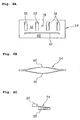
- the cell body 24 also includes a plurality of soft mount cutouts 36, which are utilized with a plurality of soft mounts or supports 38, as illustrated in Fig. 3. Each of the cutouts 36 communicate with the interior of the cell body 24 through respective passageways 40.
- Each soft mount 38 includes a resilient tongue or blade spring 42 which is sized to extend through the passageway 40 when mounted on the cutout 36. The blade 42 is held between an upper block 44 and a lower block 46, which are clamped together by securing devices, such as bolts 48.
- the blades 42 are positioned at an angle ⁇ , defined by the blade 42 and a plane orthogonal to the inner wall 32 of the cell body 24, such that when the blades are deformed by a desired fraction of the lens 10 weight, a tip portion 50 of the blade 42 is parallel to the surface of the ridge 12 on the lens 10. This is illustrated in Fig. 3A. A postion of the blade 42 is shown with a broken line in Fig. 3A when the lens 10 is not loaded into the cell 20.
- the bolts 48 also are utilized to mount the soft mounts 38 in the cutouts 36.
- the tip portion 50 of the blade 42 extends through the passageway 40 and forms a plurality of support members for the lens 10, in addition to the radial flexure mount seats 34.
- a set of the soft supports 38 are selected for distributing the gravitational load without overconstraining the lens.
- the soft supports include a set of nine (9) cantilever blades 42 for supporting a portion of the weight of the lens 10 in the optical axis direction.
- the cantilever blades 42 are compliant in the optical axis direction. Therefore, they do not overconstrain the lens positioning as determined by the three seats 34 on the radial flexure mounts 22. Instead, the blades 42 simply provide more distributed support of the lens 10 to counter any distortion due to gravity.
- An additional advantage of the soft mounts' compliance is the low sensitivity of supporting force to mechanical machining tolerances.
- the cell 20 is distorted, e.g., because it is pressed against a nonflat surface, the cell distortion will not cause a corresponding significant lens distortion. Specifically, even if cell distortion alters the location of one of the lens seats 34, because the lens 10 is not overconstrained in the optical direction, any resulting distortion of the lens 10 will be minimized.
- the soft mounts 38 should also be compliant in the radial direction to allow differential expansion.
- Cantilever springs are not compliant in the radial direction and can therefore create undesirable radial forces.
- the maximum undesirable force on the lens 10, however, is limited by the low contact force and the coefficient of friction between the cantilever spring tip 50 and the lens 10.
- Alternative soft mount springs are possible, including compressed or extended coil springs, magnets, or other suitable springs, which may or may not have radial compliance.
- the set of nine (9) soft mount blades 42 are evenly spaced in sets of three (3) between each of the three (3) radial flexure mounts 22, as illustrated in Fig 2A and diagrammatically in Fig. 4. This distributes the load and provides along with the seats 34 a nearly symmetrical lens support, with each blade 42 and each seat 34 designed to support one twelfth of the gravitational load of the lens 10.
- Other sets of soft supports 38 also could be utilized, such as three (3), six (6), or more, which can also be evenly spaced with the seats 34.
- the spring assembly 52 is illustrated in Figs. 3, 5, 6A-C and 7.
- the spring assembly 52 includes a spring member 54, best illustrated in the deformed state in Figs. 6A-C.
- the spring member 54 includes a first spring portion 56, which is designed to bow in one direction with a plurality of slots 58. The portion 56 is separated from a second oppositely bowed spring portion 60 by a longitudinal slot 62.
- the spring assembly 52 includes the member 54, a locator plate 64, a clamping block 66 and a spacer block 68.
- the plate 64 includes an aperture 70 for locating spacer block 68, a mounting aperture 72 and a locator slot 74 in an end 76.
- the spring member 54 and the block 66 include matching mounting apertures 78, 80.
- the block 66 further includes a depending locating portion 82, which bears against the member 54 and fits into the locator slot 74, when the spring assembly 52 is mounted onto the radial flexure mount 22.
- the locating portion 82 of the clamping block 66 fits into the locator slot 23 of the radial flexure mount.
- the spring assembly 52 is secured together and mounted with a bolt 84, such as a hex socket head bolt as illustrated.
- the spring assembly 52 is mounted utilizing the bolt 84 and an appropriate wrench 86, which is utilized to tighten the bolt into a threaded passageway 88 (Fig. 2B) in the radial flexure mount 22.
- an anti-torque tool 90 is engaged into a pair of apertures 92 (Figs. 2B and 2C) formed in the top of the radial flexure mount 22.
- the tool 90 includes a pair of arms 94, each of which include a pin or rod 96 which matches the apertures 92 and is engaged therein to prevent stress when the bolt 84 is tightened.
- the tool 90 includes a handle 98 from which the arms 94 extend and which is utilized to maintain the spring assembly 52 in the proper location during assembly and disassembly.
- FIG. 8 a second embodiment of an improved lens cell 100 of the present invention is illustrated.
- the cell 100 is very similar in overall structure to the cell 20 and the same numerals are utilized to indicate the same or functionally the same elements, describing in detail only the major differences in the cell 100 and the mounting structure thereof.
- the cell 100 has a plurality of radial flexure mounts 102, which are very similar to the radial flexure mounts 22, but are formed to support a different spring assembly 104.
- the spring assembly 104 is functionally similar to the spring assembly 52, however, the spring assembly 104 differs in structure as described below.
- the radial flexure mounts 102 include the lens seats 34 as before. Additionally, the radial flexure mount 102 and flexures 109, 110 are formed by a slot 106 in a cell body 108, as in the above described embodiment. In this second embodiment, however, a leaf-type clamping spring 116 provides the clamping force on the lens 10.
- the clamping spring assembly 104 includes an elongated clamping block 112, which has a notch 114 formed in one side thereof to accommodate the mounting and flexing of the leaf-type spring blade member 116.
- the spring member 116 is mounted into a second notch 118. which is formed in the bottom of the block 112 and extends beyond the notch 114.
- the spring member 116 resiliently biases a lens clamp block 120 having top and bottom arms 121, 123 to clamp the lens 10 (not illustrated) into the seat 34.
- the block 120 is slidingly engaged in an alignment slot 122, which is formed in the radial flexure mount 102.
- the clamping spring assembly 104 is mounted onto the radial flexure mount 102 utilizing a pair of bolts 84, which are threaded into mating threaded passageways 88 formed in the top of the radial flexure mount 102. As shown in greater detail in Fig.
- the lens clamp block 120 has two slots 125 formed on an upper and lower surface of the top arm 121, which define a flexural hinge 127.
- the flexural hinge 127 allows a lens contacting surface 129 of the lens clamp block 120 to conform to the lens 10 when clamped, so that small variations in the mechanical dimensions of the lens 10 or the radial flexure mount 102 do not prevent surface contact of the clamp.
- the clamping spring assembly 104 again is mounted with the bolts 84, while aligned against torque stresses utilizing an antitorque tool 124.
- the tool 124 again has a pair of arms 126, 128, each of which include the depending rod 96, which again are engaged into the apertures 92 formed in the radial flexure mount 102.
- the tool 124 again substantially eliminates torque stresses during assembly and diassembly of the clamping spring assembly 104 on the radial flexure mount 102.
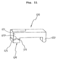
- the lens cell 100 also preferably includes a plurality of soft mounts 130, which are functionally equivalent to the soft mounts 38 described above with respect to the first embodiment.
- the mounts 130 include the blade 42, clamped by a pair of the bolts 48 inserted through a pair of dove-tailed blocks 132 and 134.
- One of the pair of blocks 134 includes a pair of end notches 136, 138 which are mated with a pair of complementary fingers 140, 142 formed on the other of the pair of blocks 132.
- the dove-tailed structure formed by the blocks 132, 134 insures that the blocks 132, 134 and blade spring 42 do not slip relative to each other when the bolts 48 are tightened.
- the present invention includes a mechanically clamped lens 10 which is constrained quasi-kinematically around the perimeter 16 of the lens.
- the cell 20 or 100 provides a three point mounting on small area seats 34 to avoid any substantial overconstraint of the lens 10 by the flat surface contact provided by the seats 34.
- Each of the seats 34 are part of the radial flexure mounts 22 or 102 which allow radial differential expansion of the lens 10, but which are stiff both vertically and tangentially to maintain a high mounting stiffness of the lens 10 which provides the desirable high frequency resonant modes.
- the spring assembly 52 or 104 mechanically clamps the lens 10 directly above the seats 34 to eliminate any potential moments caused by offsets between the clamp and seat forces.
- the problems inherent in adhesives of outgassing and destructive disassembly are avoided.
- the spring assembly 52 or 104 With the compliant clamping mechanism disclosed, the clamping force is applied substantially uniformly and constantly, despite some potential mechanical and dimensional differences due to mechanical tolerances.
- the clamping mechanisms are attached to the radial flexure mounts 22 or 102 to prevent overconstraint of the lens 10 due to differential expansion of the lens 10 and cell 20 or 100.
- each lens seat 34 can be provided on the inner wall 32 with the spring assembly 52 or 104 provided above the lens seat 34.
- the radial flexure mounts 22 or 102 function only to provide radial alignment.
- the addition of the soft mounts 38 or 130 to the support structure provided by the radial flexure mounts 22 and 102 further spreads the gravitational load from the three seats 34 to an additional number of points, preferably twelve as described.
- the applicants have analyzed the lens loading and have determined that the twelve peripheral support points on the lens 10 provide substantially optimum performance for prevention of gravity deformation.
- the blades 42 of the soft mounts 38 or 130 preferably are highly compliant cantilever-type springs formed from a flat material (e.g., metal, ceramic or other suitably flat material) of very precise thickness. The precise thickness minimizes the stiffness variation between the blades 42.
- any variation in thickness also can be compensated by varying the width of the blades 42 to maintain the desired uniformity in stiffizess.
- the slots 26 and 106, as well as the blades 42 preferably are formed by utilizing wire electron discharge machining (EDM), which is very precise and does not create internal stresses in the material.
- EDM wire electron discharge machining
- the blades 42 could be replaced by coil springs or other types of biasing mechanisms (not illustrated).
- the lens mounting structure according to principles of the present invention is applicable in a photolithography system (exposure apparatus) such as a scanning type photolithography system which exposes a mask pattern on a substrate by moving a mask, held on a mask stage, and a substrate, held on a substrate stage, synchronously (see US Patent 5,473,410). Additionally, the present invention is applicable to a step-and-repeat type photolithography system that exposes a mask pattern while a mask and a substrate are stationary and moves the substrate in successive steps. Further, the present invention can also be applied to a proximity photolithography system that exposes a mask pattern by closely locating a mask and a substrate without the use of a projection optical system.
- a photolithography system need not be limited to a photolithography system in semiconductor manufacturing. For instance, it can be widely applied to an LCD photolithography system which exposes a liquid crystal display device pattern onto a rectangular glass plate and a photolithography system for manufacturing a thin film magnetic head.
- a light source for the photolithography system not only g-line (436 nm), i-line (365 nm), KrF excimer laser (248 nm), ArF excimer laser (193 nm) and F 2 laser (157 nm) can be used, but also charged particle beams such as x-ray and electron beam can be used.
- charged particle beams such as x-ray and electron beam
- thermionic emission type lanthanum hexaboride (LaB 6 ) or tantalum (Ta) can be used as an electron gun.
- the structure could be such that either a mask is used or a pattern can be directly formed on a substrate without the use of a mask.
- the system need not be limited to a reduction system. It could also be a lx or magnification system.
- the optical system when far ultra-violet rays such as the excimer laser is used, glass materials such as quartz and fluorite that transmit far ultra-violet rays is preferable to be used.
- the optical system should preferably be either catadioptric or refractive (a reticle should also preferably be a reflective type), and when an electron beam is used, electron optics should preferably consist of electron lenses and deflectors. Needless to say, the optical path for the electron beams should be in a vacuum.
- the linear motors can be either an air levitation type employing air bearings or a magnetic levitation type using Lorentz force or reactance force.
- the stage could move along a guide, or it could be a guideless type stage which uses no guide.
- the stage could be driven by a planar motor, which drives the stage by electromagnetic force generated by a magnet unit having two-dimensionally arranged magnets and an armature coil unit having two-dimensionally arranged coils in facing positions.
- a planar motor which drives the stage by electromagnetic force generated by a magnet unit having two-dimensionally arranged magnets and an armature coil unit having two-dimensionally arranged coils in facing positions.
- reaction forces generated by the wafer (substrate) stage motion can be mechanically released to the floor (ground) by use of a frame member as described in US Patent 5,528,118 and published Japanese patent JP Hei 8-166475. Additionally, reaction forces generated by the reticle (mask) stage motion can be mechanically released to the floor (ground) by use of a frame member as described in US Patent 5,874,820 and published Japanese patent JP Hei 8-330224.
- a photolithography system can be built by assembling various subsystems, including each element listed in the appended claims, in such a manner that prescribed mechanical accuracy, electrical accuracy and optical accuracy are maintained.
- every optical system is adjusted to achieve its optical accuracy.
- every mechanical system and every electrical system are adjusted to achieve their respective mechanical and electrical accuracies.
- the process of assembling each subsystem into a photolithography system includes mechanical interfaces, electrical circuit wiring connections and air pressure plumbing connections between each subsystem. Needless to say, there is also a process where each subsystem is assembled prior to assembling a photolithography system from the various subsystems. Once a photolithography system is assembled using the various subsystems, total adjustment is performed to make sure that every accuracy is maintained in the complete photolithography system. Additionally, it is desirable to manufacture an exposure system in a clean room where the temperature and cleanliness are controlled.
- step 1201 the device's function and performance characteristics are designed.
- step 1202 a mask (reticle) having a pattern is designed according to the previous designing step, and in a parallel step 1203 a wafer is made from a silicon material.
- the mask pattern designed in step 1202 is exposed onto the wafer from step 1203 in step 1204 by a photolithography system described hereinabove in accordance with the present invention.
- step 1205 the semiconductor device is assembled (including the dicing process, bonding process and packaging process), then finally the device is inspected in step 1206.
Landscapes
- Physics & Mathematics (AREA)
- General Physics & Mathematics (AREA)
- Optics & Photonics (AREA)
- Epidemiology (AREA)
- Engineering & Computer Science (AREA)
- Environmental & Geological Engineering (AREA)
- Health & Medical Sciences (AREA)
- Public Health (AREA)
- Lens Barrels (AREA)
- Mounting And Adjusting Of Optical Elements (AREA)
- Exposure And Positioning Against Photoresist Photosensitive Materials (AREA)
- Prostheses (AREA)
- Preparing Plates And Mask In Photomechanical Process (AREA)
- Fuel Cell (AREA)
Claims (9)
- Anordnung zur Halterung einer Linse (10), mit:einer Linsenzelle (20; 100), die in der Lage ist, die Linse (10) um ihren Umfangsrand herum zu halten;mehreren radialen Biegehaltern (22; 102), die an der Linsenzelle (20; 100) befestigt und in der Lage sind, sich radial zu biegen, um Ausdehnung oder Schrumpfung der Linsenzelle infolge von Temperaturänderungen auszugleichen und dabei die Spannungsbeanspruchung der Linse zu minimieren,dadurch gekennzeichnet, daß
jeder radiale Biegehalter ein Paar von Biegearmen (28, 30; 109, 110) aufweist, die sich an entgegengesetzten Enden des radialen Biegehalters erstrecken, und einen Sitz (34) aufweist, der an einer inneren Oberfläche des radialen Biegehalters montiert ist, um den Rand der Linse zu halten;
wobei die Enden der beiden Biegearme (28, 30; 109, 110) an der Linsenzelle (20; 100) befestigt sind;
und daß mehrere weiche Halter (38; 130) zwischen benachbarten radialen Biegehaltern angeordnet sind, wobei jeder weiche Halter einen nachgiebigen Träger (42) aufweist, der den Rand der Linse berührt, um zumindest einen Teil des Gewichts der Linse aufzunehmen. - Anordnung nach Anspruch 1, bei der die weichen Halter (38; 130) eine Auslegerklinge (42) aufweisen, die einen Teil des Gewichts der Linse (10) an deren Rand nachgiebig aufnimmt.
- Anordnung nach Anspruch 1, bei der die weichen Halter ein Federelement aufweisen, das einen Teil des Gewichts der Linse an deren Rand aufnimmt.
- Anordnung nach einem der Ansprüche 1 bis 3, bei der jeder Sitz (34) sich so von einem Mittelpunkt des radialen Biegehalters (22; 102) aus erstreckt, daß die Linse (10) am den Sitz an einer Stelle in der Ebene der Biegearme (28, 30; 109, 110) anliegt, so daß die axiale Bewegung der Linse keine nachteiligen Auswirkungen auf die radialen Biegehalter hat.
- Anordnung nach einem der Ansprüche 1 bis 4, bei der die radialen Biegehalter (22; 102) eine Federanordnung (52; 104) aufweisen, die darauf montiert ist, um die Linse (10) elastisch auf den Sitz (34) zu klemmen.
- Anordnung nach Anspruch 5, bei der die Federanordnung (52, 104) eine nachgebende Klammer (54; 116) aufweist.
- Anordnung nach einem der Ansprüche 1 bis 6, bei der die weichen Halter (38; 130) in der Richtung der optischen Achse nachgiebig sind, so daß die Anordnung im wesentlichen unempfindlich gegenüber Fehlausrichtungen der weichen Halter in Richtung der optischen Achse ist.
- Anordnung nach Anspruch 7, bei der die weichen Halter (38; 130) eine nachgiebige Struktur (42) aufweisen, die am Rand der Linse (10) anliegt und die Linse in radialer Richtung derselben nicht wesentlich einschränkt.
- Belichtungsgerät, das ein Muster auf ein Substrat überträgt, mit einer Anordnung nach einem der Ansprüche 1 bis 8 zur Linsenhalterung.
Applications Claiming Priority (2)
| Application Number | Priority Date | Filing Date | Title |
|---|---|---|---|
| US386255 | 1999-08-31 | ||
| US09/386,255 US6239924B1 (en) | 1999-08-31 | 1999-08-31 | Kinematic lens mounting with distributed support and radial flexure |
Publications (3)
| Publication Number | Publication Date |
|---|---|
| EP1081521A2 EP1081521A2 (de) | 2001-03-07 |
| EP1081521A3 EP1081521A3 (de) | 2004-01-02 |
| EP1081521B1 true EP1081521B1 (de) | 2006-04-19 |
Family
ID=23524830
Family Applications (1)
| Application Number | Title | Priority Date | Filing Date |
|---|---|---|---|
| EP00116461A Expired - Lifetime EP1081521B1 (de) | 1999-08-31 | 2000-07-29 | Kinematische Linsenhalterung |
Country Status (7)
| Country | Link |
|---|---|
| US (1) | US6239924B1 (de) |
| EP (1) | EP1081521B1 (de) |
| JP (1) | JP4622058B2 (de) |
| KR (1) | KR100654117B1 (de) |
| AT (1) | ATE323893T1 (de) |
| DE (1) | DE60027371T2 (de) |
| TW (1) | TW490599B (de) |
Cited By (1)
| Publication number | Priority date | Publication date | Assignee | Title |
|---|---|---|---|---|
| US9134501B2 (en) | 2006-09-14 | 2015-09-15 | Carl Zeiss Smt Gmbh | Optical element unit and method of supporting an optical element |
Families Citing this family (84)
| Publication number | Priority date | Publication date | Assignee | Title |
|---|---|---|---|---|
| US6650412B1 (en) * | 1999-09-10 | 2003-11-18 | Kaiser Optical Systems | Thermal compensation for optical apparatus |
| KR20030051421A (ko) * | 2000-03-31 | 2003-06-25 | 가부시키가이샤 니콘 | 광학 부재의 유지 방법 및 장치, 광학 장치, 노광 장치 및디바이스 제조 방법 |
| JP4945845B2 (ja) * | 2000-03-31 | 2012-06-06 | 株式会社ニコン | 光学素子保持装置、鏡筒及び露光装置並びにマイクロデバイスの製造方法。 |
| US6400516B1 (en) * | 2000-08-10 | 2002-06-04 | Nikon Corporation | Kinematic optical mounting |
| US6473245B1 (en) | 2000-08-10 | 2002-10-29 | Nikon Corporation | Catadioptric lens barrel structure having a plurality of support platforms and method of making the same |
| US6577457B1 (en) | 2000-08-10 | 2003-06-10 | Nikon Corporation | Catadioptric lens barrel structure having a kinematic alignment structure and method for aligning two planar surfaces |
| US6639740B1 (en) | 2000-08-10 | 2003-10-28 | Nikon Corporation | Catadioptric lens barrel structure having a plurality of split lens barrels and a support structure supporting the split lens barrels |
| AU2001277758A1 (en) | 2000-08-18 | 2002-03-04 | Nikon Corporation | Optical element holding device |
| US6653639B1 (en) * | 2000-10-17 | 2003-11-25 | Nikon Corporation | Chuck for mounting reticle to a reticle stage |
| JP4081813B2 (ja) * | 2000-11-10 | 2008-04-30 | 株式会社ニコン | 光学装置、露光装置、及びデバイス製造方法 |
| US6439139B1 (en) * | 2000-11-17 | 2002-08-27 | Owens Corning Fiberglas Technology, Inc. | Method for recycling building materials |
| DE10100546A1 (de) * | 2001-01-08 | 2002-07-11 | Zeiss Carl | Vorrichtung zur Verstellung eines optischen Elementes in einem Objektiv |
| US6381081B1 (en) * | 2001-01-19 | 2002-04-30 | The United States Of America As Represented By The Administrator Of The National Aeronautics And Space Administration | Flexure-ring for centering a concave lens in a bore of a housing for an optical system |
| JP2002365013A (ja) * | 2001-06-04 | 2002-12-18 | Fuji Photo Optical Co Ltd | 光波干渉計用参照基準板の支持装置 |
| US6788389B2 (en) * | 2001-07-10 | 2004-09-07 | Nikon Corporation | Production method of projection optical system |
| US6603611B1 (en) * | 2001-11-06 | 2003-08-05 | Itt Manufacturing Enterprises, Inc. | Mount for ultra-high performance of optical components under thermal and vibrational distortion conditions |
| TW577108B (en) * | 2001-11-07 | 2004-02-21 | Nikon Corp | Optical device and the manufacturing method thereof, optical system, and manufacturing method of exposure device and micro-device |
| US20030098965A1 (en) * | 2001-11-29 | 2003-05-29 | Mike Binnard | System and method for supporting a device holder with separate components |
| US6909493B2 (en) | 2002-03-20 | 2005-06-21 | Canon Kabushiki Kaisha | Correction member, retainer, exposure apparatus, and device fabrication method |
| TWI223863B (en) * | 2002-04-22 | 2004-11-11 | Nikon Corp | Support apparatus, optical apparatus, exposure apparatus and manufacturing method of device |
| JP4333078B2 (ja) * | 2002-04-26 | 2009-09-16 | 株式会社ニコン | 投影光学系、該投影光学系を備えた露光装置および該投影光学系を用いた露光方法並びにデバイス製造方法 |
| US7245361B2 (en) | 2002-06-04 | 2007-07-17 | Nikon Corporation | Method for evaluating refractive index homogeneity of optical member |
| JPWO2003102529A1 (ja) * | 2002-06-04 | 2005-09-29 | 株式会社ニコン | 光学部材の屈折率均質性を評価する方法 |
| US20030234918A1 (en) * | 2002-06-20 | 2003-12-25 | Nikon Corporation | Adjustable soft mounts in kinematic lens mounting system |
| US20030235682A1 (en) * | 2002-06-21 | 2003-12-25 | Sogard Michael R. | Method and device for controlling thermal distortion in elements of a lithography system |
| US20030234916A1 (en) * | 2002-06-21 | 2003-12-25 | Nikon Corporation | Soft supports to reduce deformation of vertically mounted lens or mirror |
| US6922293B2 (en) | 2002-07-02 | 2005-07-26 | Nikon Corporation | Kinematic optical mounting assembly with flexures |
| EP1380899B1 (de) * | 2002-07-11 | 2014-09-03 | ASML Netherlands B.V. | Lithographischer Apparat und Verfahren zur Herstellung einer Vorrichtung |
| TWI266151B (en) * | 2002-07-11 | 2006-11-11 | Asml Netherlands Bv | Lithographic apparatus and device manufacturing method |
| US6649865B1 (en) * | 2002-08-07 | 2003-11-18 | Great Computer Corp. | Control method for optical lens-seat on a laser processing machine |
| JP2005534998A (ja) * | 2002-08-08 | 2005-11-17 | カール・ツァイス・エスエムティー・アーゲー | イメージングデバイスにおける光学式アセンブリを保持するための装置 |
| US20040080730A1 (en) * | 2002-10-29 | 2004-04-29 | Michael Binnard | System and method for clamping a device holder with reduced deformation |
| WO2004086148A1 (de) * | 2003-03-26 | 2004-10-07 | Carl Zeiss Smt Ag | Vorrichtung zur deformationsarmen austauschbaren lagerung eines optischen elements |
| JP2004363559A (ja) * | 2003-05-14 | 2004-12-24 | Canon Inc | 光学部材保持装置 |
| JP2004347814A (ja) * | 2003-05-21 | 2004-12-09 | Canon Inc | 保持装置、露光装置及びデバイス製造方法 |
| DE602004024302D1 (de) * | 2003-06-06 | 2010-01-07 | Nippon Kogaku Kk | Halteeinrichtung für optische elemente, objektivtubus, belichtungseinrichtung und herstellungsverfahren für bauelemente |
| DE102004025832A1 (de) * | 2004-05-24 | 2005-12-22 | Carl Zeiss Smt Ag | Optikmodul für ein Objektiv |
| US7697222B2 (en) * | 2003-12-25 | 2010-04-13 | Nikon Corporation | Apparatus for holding optical element, barrel, exposure apparatus, and device producing method |
| EP1577693B1 (de) * | 2004-02-26 | 2011-07-13 | Carl Zeiss SMT GmbH | Objektiv mit wenigstens einem optischen Element |
| DE102004014641B4 (de) * | 2004-03-09 | 2007-09-13 | Carl Zeiss Smt Ag | Anordnung zur Lagerung eines optischen Bauelements |
| WO2006096045A1 (en) * | 2005-03-09 | 2006-09-14 | Stichting Astron | Suspension for keeping an object aligned during large temperature variations; optical system provided with such a suspension. |
| US20060238735A1 (en) * | 2005-04-22 | 2006-10-26 | Vladimir Kamenov | Optical system of a projection exposure apparatus |
| WO2006134910A1 (ja) * | 2005-06-14 | 2006-12-21 | Nikon Corporation | 光学素子、光学素子保持装置、露光装置、及びデバイス製造方法 |
| EP1899756A2 (de) * | 2005-07-01 | 2008-03-19 | Carl Zeiss SMT AG | Anordnung zur lagerung eines optischen bauelements |
| JP5243957B2 (ja) | 2005-08-16 | 2013-07-24 | カール・ツァイス・エスエムティー・ゲーエムベーハー | 液浸リソグラフィー用オブジェクティブ |
| TWI372271B (en) * | 2005-09-13 | 2012-09-11 | Zeiss Carl Smt Gmbh | Optical element unit, optical element holder, method of manufacturing an optical element holder, optical element module, optical exposure apparatus, and method of manufacturing a semiconductor device |
| WO2007132862A1 (ja) * | 2006-05-16 | 2007-11-22 | Nikon Corporation | 投影光学系、露光方法、露光装置、及びデバイス製造方法 |
| US8416386B2 (en) * | 2007-03-13 | 2013-04-09 | Nikon Corporation | Conforming seats for clamps used in mounting an optical element, and optical systems comprising same |
| JPWO2008146655A1 (ja) * | 2007-05-25 | 2010-08-19 | 株式会社ニコン | 光学素子保持装置、鏡筒及び露光装置ならびにデバイスの製造方法 |
| WO2009024192A1 (en) * | 2007-08-23 | 2009-02-26 | Carl Zeiss Smt Ag | Optical element module with minimized parasitic loads |
| US7990628B1 (en) * | 2007-08-29 | 2011-08-02 | Tessera MEMS Technologies, Inc. | Planar flexure system with high pitch stiffness |
| DE102007047186B4 (de) * | 2007-10-02 | 2014-01-09 | Carl Zeiss Sms Gmbh | Aufnahmevorrichtung zur Aufnahme einer Photolithographiemaske |
| DE102007063305A1 (de) * | 2007-12-27 | 2009-07-02 | Carl Zeiss Smt Ag | Optische Einrichtung mit einer Federeinrichtung mit einem Bereich konstanter Federkraft |
| DE102008022211B3 (de) * | 2008-05-06 | 2010-02-25 | Carl Zeiss Surgical Gmbh | Linsenträger sowie optische Baugruppe |
| US9335641B2 (en) * | 2008-07-21 | 2016-05-10 | Asml Netherlands B.V. | Optical element mount for lithographic apparatus |
| US8591048B2 (en) * | 2009-10-30 | 2013-11-26 | Flir Systems, Inc. | Spatially efficient kinematic mirror mount |
| US8919724B2 (en) | 2010-08-24 | 2014-12-30 | Raytheon Company | Mount for cryogenic fast switching mechanism |
| CN102486564B (zh) * | 2010-12-06 | 2014-10-29 | 上海微电子装备有限公司 | 透镜挠性固定装置 |
| CN102243359B (zh) * | 2011-06-20 | 2012-11-14 | 北京空间机电研究所 | 一种大孔径透镜挠性支撑方法 |
| JP5695011B2 (ja) * | 2012-10-31 | 2015-04-01 | カール・ツァイス・エスエムティー・ゲーエムベーハー | 寄生負荷最小化光学素子モジュール |
| DE202013011933U1 (de) | 2013-01-23 | 2014-10-28 | Jenoptik Optical Systems Gmbh | Thermisch kompensierte optische Baugruppe mit einem formschlüssig gehaltenen optischen Bauelement |
| CN103901571B (zh) * | 2014-02-13 | 2016-03-09 | 中国科学院上海光学精密机械研究所 | 大型透反式镜片非垂直放置的挠性支撑装置和支撑方法 |
| CN103885302B (zh) * | 2014-04-04 | 2016-03-30 | 中国科学院光电技术研究所 | 一种装卡光学元件的力反馈精密支撑装置 |
| JP5848470B2 (ja) * | 2015-02-05 | 2016-01-27 | カール・ツァイス・エスエムティー・ゲーエムベーハー | 寄生負荷最小化光学素子モジュール |
| CN106383395A (zh) * | 2015-07-29 | 2017-02-08 | 上海微电子装备有限公司 | 一种大口径侧立镜组结构 |
| CN105371763B (zh) * | 2015-12-01 | 2017-09-19 | 中国科学院长春光学精密机械与物理研究所 | 一种大口径光学元件卧式电磁支撑装置 |
| CN107329225B (zh) * | 2016-04-29 | 2020-06-16 | 上海微电子装备(集团)股份有限公司 | 侧立镜组及其安装方法 |
| US20170363833A1 (en) * | 2016-06-17 | 2017-12-21 | Corning Incorporated | Polymer-free compliant optical member support |
| US10015378B2 (en) | 2016-09-15 | 2018-07-03 | Microsoft Technology Licensing, Llc | Kinematic mount for split camera |
| TWI597536B (zh) * | 2016-10-27 | 2017-09-01 | 財團法人國家實驗硏究院 | 用於支撐鏡片的支撐裝置與方法及用於支 撐功能元件的支撐組件 |
| US10678018B2 (en) * | 2017-10-23 | 2020-06-09 | Magna Electronics Inc. | Camera for vehicle vision system with replaceable lens |
| LT3759537T (lt) * | 2018-03-02 | 2023-08-25 | Gooch And Housego Plc | Montavimo žiedas optinio įtaiso centravimui palaikyti |
| GB201804952D0 (en) * | 2018-03-27 | 2018-05-09 | Pxyl Ltd | Improved scanning optical microscope |
| US11692816B2 (en) | 2018-04-27 | 2023-07-04 | Cognex Corporation | Mounting arrangement for optical systems |
| EP3608627B1 (de) | 2018-08-09 | 2023-11-08 | Cognex Corporation | Positionierungssystem für komponenten von optischen systemen |
| CN109387918A (zh) * | 2018-12-03 | 2019-02-26 | 长春奥普光电技术股份有限公司 | 一种主三一体镜定位组合装置及方法 |
| EP3792673A1 (de) * | 2019-09-16 | 2021-03-17 | ASML Netherlands B.V. | Anordnung zur bündelung von breitbandstrahlung |
| WO2021043516A1 (en) * | 2019-09-03 | 2021-03-11 | Asml Netherlands B.V. | Assembly for collimating broadband radiation |
| CN110568576B (zh) * | 2019-09-09 | 2021-04-06 | 中国科学院长春光学精密机械与物理研究所 | 一种透镜柔性支撑装置 |
| CN112068277B (zh) * | 2020-08-31 | 2021-08-20 | 中国科学院长春光学精密机械与物理研究所 | 大口径光学透镜的多级柔性支撑结构 |
| CN112128546B (zh) * | 2020-09-30 | 2021-11-05 | 中国科学院国家天文台南京天文光学技术研究所 | 用于大尺寸拼接光学元件的支撑结构及其安装方法 |
| DE102021200131A1 (de) * | 2021-01-11 | 2022-07-14 | Carl Zeiss Smt Gmbh | Baugruppe mit einem Entkopplungsgelenk zur mechanischen Lagerung eines Elements |
| CN113917645B (zh) * | 2021-11-01 | 2023-03-31 | 中国科学院光电技术研究所 | 一种镜片弹性支撑装置 |
| CN114486939B (zh) * | 2022-04-08 | 2022-07-22 | 欧普康视科技股份有限公司 | 一种镜片划痕检测系统及方法 |
Family Cites Families (14)
| Publication number | Priority date | Publication date | Assignee | Title |
|---|---|---|---|---|
| US2808762A (en) * | 1956-06-25 | 1957-10-08 | Bausch & Lomb | Lens mounting means |
| US2937571A (en) | 1957-10-08 | 1960-05-24 | Ernest B Thompson | Optical lens mount |
| DE1262041B (de) * | 1965-07-13 | 1968-02-29 | Voigtlaender Ag | Halterung fuer Linsen |
| US3601343A (en) | 1969-09-05 | 1971-08-24 | North American Rockwell | Strain-free mount |
| JPS58159509A (ja) * | 1982-03-18 | 1983-09-21 | Olympus Optical Co Ltd | レンズ保持装置 |
| JPS58187907A (ja) * | 1982-04-27 | 1983-11-02 | Olympus Optical Co Ltd | レンズ保持装置 |
| US4733945A (en) | 1986-01-15 | 1988-03-29 | The Perkin-Elmer Corporation | Precision lens mounting |
| US4929054A (en) | 1986-04-28 | 1990-05-29 | The Perkin-Elmer Corporation | Mounting for high resolution projection lenses |
| US4726671A (en) | 1986-06-19 | 1988-02-23 | The Perkin-Elmer Corporation | High resonance adjustable mirror mount |
| US5428482A (en) * | 1991-11-04 | 1995-06-27 | General Signal Corporation | Decoupled mount for optical element and stacked annuli assembly |
| JP3412638B2 (ja) * | 1993-01-19 | 2003-06-03 | 株式会社ニコン | レンズの保持具 |
| JPH06250061A (ja) * | 1993-02-26 | 1994-09-09 | Nikon Corp | 光学部材保持装置 |
| JP3956454B2 (ja) | 1997-11-18 | 2007-08-08 | 株式会社ニコン | レンズ支持装置、支持方法および投影露光装置 |
| DE19904152A1 (de) * | 1999-02-03 | 2000-08-10 | Zeiss Carl Fa | Baugruppe aus einem optischen Element und einer Fassung |
-
1999
- 1999-08-31 US US09/386,255 patent/US6239924B1/en not_active Expired - Lifetime
-
2000
- 2000-03-21 TW TW089105120A patent/TW490599B/zh not_active IP Right Cessation
- 2000-05-26 KR KR1020000028700A patent/KR100654117B1/ko active IP Right Grant
- 2000-07-11 JP JP2000210029A patent/JP4622058B2/ja not_active Expired - Lifetime
- 2000-07-29 AT AT00116461T patent/ATE323893T1/de not_active IP Right Cessation
- 2000-07-29 DE DE60027371T patent/DE60027371T2/de not_active Expired - Fee Related
- 2000-07-29 EP EP00116461A patent/EP1081521B1/de not_active Expired - Lifetime
Cited By (1)
| Publication number | Priority date | Publication date | Assignee | Title |
|---|---|---|---|---|
| US9134501B2 (en) | 2006-09-14 | 2015-09-15 | Carl Zeiss Smt Gmbh | Optical element unit and method of supporting an optical element |
Also Published As
| Publication number | Publication date |
|---|---|
| KR20010020912A (ko) | 2001-03-15 |
| DE60027371D1 (de) | 2006-05-24 |
| ATE323893T1 (de) | 2006-05-15 |
| EP1081521A3 (de) | 2004-01-02 |
| US6239924B1 (en) | 2001-05-29 |
| JP4622058B2 (ja) | 2011-02-02 |
| DE60027371T2 (de) | 2007-06-21 |
| KR100654117B1 (ko) | 2006-12-05 |
| EP1081521A2 (de) | 2001-03-07 |
| JP2001074991A (ja) | 2001-03-23 |
| TW490599B (en) | 2002-06-11 |
Similar Documents
| Publication | Publication Date | Title |
|---|---|---|
| EP1081521B1 (de) | Kinematische Linsenhalterung | |
| US7113263B2 (en) | Supporting structure of optical element, exposure apparatus having the same, and manufacturing method of semiconductor device | |
| US6859337B2 (en) | Optical-element mountings exhibiting reduced deformation of optical elements held thereby | |
| US7345834B2 (en) | Optical element holding system, barrel, exposure apparatus, and device manufacturing method | |
| US6400516B1 (en) | Kinematic optical mounting | |
| US6574053B1 (en) | Kinematic alignment structure for placement between components axially aligned in a cylindrical body | |
| US6922293B2 (en) | Kinematic optical mounting assembly with flexures | |
| US8416386B2 (en) | Conforming seats for clamps used in mounting an optical element, and optical systems comprising same | |
| US20060066963A1 (en) | Holding mechanism, optical apparatus and device manufacturing method | |
| US20040027632A1 (en) | Deformable mirror with passive and active actuators | |
| US20030234918A1 (en) | Adjustable soft mounts in kinematic lens mounting system | |
| US9557560B2 (en) | Mirror unit and exposure apparatus | |
| WO2004001478A1 (en) | Kinematic lens mount with reduced clamping force and lithography system | |
| US7061577B2 (en) | Image adjustor including damping assembly | |
| US20040080730A1 (en) | System and method for clamping a device holder with reduced deformation | |
| JP2013106017A (ja) | 光学素子保持装置、光学装置、及び露光装置 | |
| US20030098965A1 (en) | System and method for supporting a device holder with separate components | |
| JP4956680B2 (ja) | 光学要素の支持構造、それを用いた露光装置及び半導体デバイスの製造方法 | |
| US20040145751A1 (en) | Square wafer chuck with mirror | |
| US7136238B2 (en) | Method of supporting and adjusting optical element in exposure apparatus | |
| JP2004093663A (ja) | 光学要素の支持手段、該光学要素の支持手段による光学系、露光装置等の光学装置、デバイス製造方法 | |
| CN115729054A (zh) | 驱动装置、曝光装置和物品制造方法 |
Legal Events
| Date | Code | Title | Description |
|---|---|---|---|
| PUAI | Public reference made under article 153(3) epc to a published international application that has entered the european phase |
Free format text: ORIGINAL CODE: 0009012 |
|
| AK | Designated contracting states |
Kind code of ref document: A2 Designated state(s): AT BE CH CY DE DK ES FI FR GB GR IE IT LI LU MC NL PT SE |
|
| AX | Request for extension of the european patent |
Free format text: AL;LT;LV;MK;RO;SI |
|
| PUAL | Search report despatched |
Free format text: ORIGINAL CODE: 0009013 |
|
| AK | Designated contracting states |
Kind code of ref document: A3 Designated state(s): AT BE CH CY DE DK ES FI FR GB GR IE IT LI LU MC NL PT SE |
|
| AX | Request for extension of the european patent |
Extension state: AL LT LV MK RO SI |
|
| 17P | Request for examination filed |
Effective date: 20040429 |
|
| AKX | Designation fees paid |
Designated state(s): AT BE CH CY DE DK ES FI FR GB GR IE IT LI LU MC NL PT SE |
|
| 17Q | First examination report despatched |
Effective date: 20041018 |
|
| GRAP | Despatch of communication of intention to grant a patent |
Free format text: ORIGINAL CODE: EPIDOSNIGR1 |
|
| GRAS | Grant fee paid |
Free format text: ORIGINAL CODE: EPIDOSNIGR3 |
|
| GRAA | (expected) grant |
Free format text: ORIGINAL CODE: 0009210 |
|
| AK | Designated contracting states |
Kind code of ref document: B1 Designated state(s): AT BE CH CY DE DK ES FI FR GB GR IE IT LI LU MC NL PT SE |
|
| PG25 | Lapsed in a contracting state [announced via postgrant information from national office to epo] |
Ref country code: IT Free format text: LAPSE BECAUSE OF FAILURE TO SUBMIT A TRANSLATION OF THE DESCRIPTION OR TO PAY THE FEE WITHIN THE PRESCRIBED TIME-LIMIT;WARNING: LAPSES OF ITALIAN PATENTS WITH EFFECTIVE DATE BEFORE 2007 MAY HAVE OCCURRED AT ANY TIME BEFORE 2007. THE CORRECT EFFECTIVE DATE MAY BE DIFFERENT FROM THE ONE RECORDED. Effective date: 20060419 Ref country code: LI Free format text: LAPSE BECAUSE OF FAILURE TO SUBMIT A TRANSLATION OF THE DESCRIPTION OR TO PAY THE FEE WITHIN THE PRESCRIBED TIME-LIMIT Effective date: 20060419 Ref country code: AT Free format text: LAPSE BECAUSE OF FAILURE TO SUBMIT A TRANSLATION OF THE DESCRIPTION OR TO PAY THE FEE WITHIN THE PRESCRIBED TIME-LIMIT Effective date: 20060419 Ref country code: FI Free format text: LAPSE BECAUSE OF FAILURE TO SUBMIT A TRANSLATION OF THE DESCRIPTION OR TO PAY THE FEE WITHIN THE PRESCRIBED TIME-LIMIT Effective date: 20060419 Ref country code: BE Free format text: LAPSE BECAUSE OF FAILURE TO SUBMIT A TRANSLATION OF THE DESCRIPTION OR TO PAY THE FEE WITHIN THE PRESCRIBED TIME-LIMIT Effective date: 20060419 Ref country code: CH Free format text: LAPSE BECAUSE OF FAILURE TO SUBMIT A TRANSLATION OF THE DESCRIPTION OR TO PAY THE FEE WITHIN THE PRESCRIBED TIME-LIMIT Effective date: 20060419 |
|
| REG | Reference to a national code |
Ref country code: GB Ref legal event code: FG4D |
|
| REF | Corresponds to: |
Ref document number: 60027371 Country of ref document: DE Date of ref document: 20060524 Kind code of ref document: P |
|
| REG | Reference to a national code |
Ref country code: IE Ref legal event code: FG4D |
|
| PG25 | Lapsed in a contracting state [announced via postgrant information from national office to epo] |
Ref country code: DK Free format text: LAPSE BECAUSE OF FAILURE TO SUBMIT A TRANSLATION OF THE DESCRIPTION OR TO PAY THE FEE WITHIN THE PRESCRIBED TIME-LIMIT Effective date: 20060719 Ref country code: SE Free format text: LAPSE BECAUSE OF FAILURE TO SUBMIT A TRANSLATION OF THE DESCRIPTION OR TO PAY THE FEE WITHIN THE PRESCRIBED TIME-LIMIT Effective date: 20060719 |
|
| PG25 | Lapsed in a contracting state [announced via postgrant information from national office to epo] |
Ref country code: GB Free format text: LAPSE BECAUSE OF NON-PAYMENT OF DUE FEES Effective date: 20060729 |
|
| PG25 | Lapsed in a contracting state [announced via postgrant information from national office to epo] |
Ref country code: ES Free format text: LAPSE BECAUSE OF FAILURE TO SUBMIT A TRANSLATION OF THE DESCRIPTION OR TO PAY THE FEE WITHIN THE PRESCRIBED TIME-LIMIT Effective date: 20060730 |
|
| PG25 | Lapsed in a contracting state [announced via postgrant information from national office to epo] |
Ref country code: MC Free format text: LAPSE BECAUSE OF NON-PAYMENT OF DUE FEES Effective date: 20060731 Ref country code: IE Free format text: LAPSE BECAUSE OF NON-PAYMENT OF DUE FEES Effective date: 20060731 |
|
| PG25 | Lapsed in a contracting state [announced via postgrant information from national office to epo] |
Ref country code: PT Free format text: LAPSE BECAUSE OF FAILURE TO SUBMIT A TRANSLATION OF THE DESCRIPTION OR TO PAY THE FEE WITHIN THE PRESCRIBED TIME-LIMIT Effective date: 20060919 |
|
| REG | Reference to a national code |
Ref country code: CH Ref legal event code: PL |
|
| PLBE | No opposition filed within time limit |
Free format text: ORIGINAL CODE: 0009261 |
|
| STAA | Information on the status of an ep patent application or granted ep patent |
Free format text: STATUS: NO OPPOSITION FILED WITHIN TIME LIMIT |
|
| 26N | No opposition filed |
Effective date: 20070122 |
|
| GBPC | Gb: european patent ceased through non-payment of renewal fee |
Effective date: 20060729 |
|
| EN | Fr: translation not filed | ||
| PG25 | Lapsed in a contracting state [announced via postgrant information from national office to epo] |
Ref country code: GR Free format text: LAPSE BECAUSE OF FAILURE TO SUBMIT A TRANSLATION OF THE DESCRIPTION OR TO PAY THE FEE WITHIN THE PRESCRIBED TIME-LIMIT Effective date: 20060720 Ref country code: FR Free format text: LAPSE BECAUSE OF FAILURE TO SUBMIT A TRANSLATION OF THE DESCRIPTION OR TO PAY THE FEE WITHIN THE PRESCRIBED TIME-LIMIT Effective date: 20070309 |
|
| PG25 | Lapsed in a contracting state [announced via postgrant information from national office to epo] |
Ref country code: LU Free format text: LAPSE BECAUSE OF NON-PAYMENT OF DUE FEES Effective date: 20060729 |
|
| PG25 | Lapsed in a contracting state [announced via postgrant information from national office to epo] |
Ref country code: FR Free format text: LAPSE BECAUSE OF FAILURE TO SUBMIT A TRANSLATION OF THE DESCRIPTION OR TO PAY THE FEE WITHIN THE PRESCRIBED TIME-LIMIT Effective date: 20060419 Ref country code: CY Free format text: LAPSE BECAUSE OF FAILURE TO SUBMIT A TRANSLATION OF THE DESCRIPTION OR TO PAY THE FEE WITHIN THE PRESCRIBED TIME-LIMIT Effective date: 20060419 |
|
| PGFP | Annual fee paid to national office [announced via postgrant information from national office to epo] |
Ref country code: NL Payment date: 20080715 Year of fee payment: 9 |
|
| PGFP | Annual fee paid to national office [announced via postgrant information from national office to epo] |
Ref country code: DE Payment date: 20081030 Year of fee payment: 9 |
|
| NLV4 | Nl: lapsed or anulled due to non-payment of the annual fee |
Effective date: 20100201 |
|
| PG25 | Lapsed in a contracting state [announced via postgrant information from national office to epo] |
Ref country code: DE Free format text: LAPSE BECAUSE OF NON-PAYMENT OF DUE FEES Effective date: 20100202 |
|
| PG25 | Lapsed in a contracting state [announced via postgrant information from national office to epo] |
Ref country code: NL Free format text: LAPSE BECAUSE OF NON-PAYMENT OF DUE FEES Effective date: 20100201 |