EP1081499A1 - Mittel zum schätzen des ladungszustands eines batterie und verfahren zum schätzen des degradierten zustands einer batterie - Google Patents
Mittel zum schätzen des ladungszustands eines batterie und verfahren zum schätzen des degradierten zustands einer batterie Download PDFInfo
- Publication number
- EP1081499A1 EP1081499A1 EP99921254A EP99921254A EP1081499A1 EP 1081499 A1 EP1081499 A1 EP 1081499A1 EP 99921254 A EP99921254 A EP 99921254A EP 99921254 A EP99921254 A EP 99921254A EP 1081499 A1 EP1081499 A1 EP 1081499A1
- Authority
- EP
- European Patent Office
- Prior art keywords
- battery
- soc
- estimating
- voltage
- pseudo
- Prior art date
- Legal status (The legal status is an assumption and is not a legal conclusion. Google has not performed a legal analysis and makes no representation as to the accuracy of the status listed.)
- Granted
Links
Images


Classifications
-
- G—PHYSICS
- G01—MEASURING; TESTING
- G01R—MEASURING ELECTRIC VARIABLES; MEASURING MAGNETIC VARIABLES
- G01R31/00—Arrangements for testing electric properties; Arrangements for locating electric faults; Arrangements for electrical testing characterised by what is being tested not provided for elsewhere
- G01R31/36—Arrangements for testing, measuring or monitoring the electrical condition of accumulators or electric batteries, e.g. capacity or state of charge [SoC]
- G01R31/389—Measuring internal impedance, internal conductance or related variables
-
- G—PHYSICS
- G01—MEASURING; TESTING
- G01R—MEASURING ELECTRIC VARIABLES; MEASURING MAGNETIC VARIABLES
- G01R31/00—Arrangements for testing electric properties; Arrangements for locating electric faults; Arrangements for electrical testing characterised by what is being tested not provided for elsewhere
- G01R31/36—Arrangements for testing, measuring or monitoring the electrical condition of accumulators or electric batteries, e.g. capacity or state of charge [SoC]
- G01R31/374—Arrangements for testing, measuring or monitoring the electrical condition of accumulators or electric batteries, e.g. capacity or state of charge [SoC] with means for correcting the measurement for temperature or ageing
Definitions
- the present invention relates to a means for estimating the state of charge of a battery, especially by using a battery model to minimize an estimation error, and an improved method for estimating the degraded state of battery (battery condition).
- a method for estimating state of charge (SOC) of a battery by adding an integrated value of charging/discharging current to an initial SOC of the battery has conventionally been known. With this method, however, it is difficult to accurately estimate the SOC of a battery because of factors such as the error inherent in integration of the charging/discharging current values, the accumulation of such error, change in the initial SOC due to self-discharge when the battery is not used, and so on.
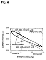
- Fig. 6 shows a relationship between current and voltage of a battery having an SOC of 68%.
- the current-voltage relationship of the battery is not linear and has a large hysteresis. If the SOC is estimated from this current-voltage relationship, a large error may result depending on where in the changes in current and voltages of the battery the SOC is judged.
- the real SOC is 68%, the SOC is judged to be 80% during increase of the charging current, and the SOC is judged to be 20% during increase of the discharging current.
- the SOC is estimated based on the battery voltage, because, even if the SOC is unchanged, the voltage of the battery changes widely reflecting the charging/discharging state of the battery immediately before the voltage is measured. Thus, accurate estimations of the SOC could not be realized by any conventional method.
- the estimation error of the SOC is particularly large in a hybrid vehicle where the battery repeats charging and discharging in short cycles.
- the degraded level of the battery is estimated in order to determine the replacement tinting of the battery or to predict occurrence of troubles.
- the state of decay of a battery can be measured out by determining the internal resistance of the battery.
- the internal resistance may be determined, for example, from the voltage of the battery after discharging a predetermined amount of discharging current for a certain period of time from the battery in a predetermined state of charge (SOC).
- SOC state of charge
- it is also possible to determine the internal resistance R from several current/voltage values, while the vehicle is driven, by Vb -R ⁇ Ib + Voc where Vb is a voltage value, Ib is a current value, and Voc is an open voltage.
- the method for determining the internal resistance of the battery using the above equation (1) it is possible to determine the internal resistance of the battery while the electric vehicle is driven.
- the influence of polarization of the battery is not considered in this method, so that a significant estimation error nay be present in the obtained internal resistance.
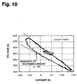
- the charging/discharging current of the battery is correlated to the voltage of the battery as shown in Fig.10, in which the discharging state is indicated by positive current values and the charging state is indicated by negative current values.
- the current/voltage characteristic of the battery includes hysteresis, so that a gradient between voltage and current, i.e., the internal resistance (-R), is changed depending on the measurement timing. This happens because the polarization is not considered, as described above.
- this conventional method can not be used to simply and accurately estimate the internal resistance of the battery.
- an object of the present invention is to provide a means for estimating the charged state of a battery capable of accurately estimating an SOC even though the battery repeats charging/ discharging in short cycles.
- Another object of the present invention is to provide a method for estimating the degraded state of battery capable of accurately measuring variations of internal resistance of the battery while the battery is used and of correctly ascertaining the degraded state of battery.
- a means for estimating the charged state of a battery in which a battery model is provided for determining a pseudo-SOC (state of charge) as a temporary value representative of the SOC of the battery, and voltage of the battery is estimated by considering the pseudo-SOC and a change in the state of the battery, whereby a real SOC is estimated by correcting the pseudo-SOC so that the estimated battery voltage is equal to an actually measured battery voltage.
- a battery model for determining a pseudo-SOC (state of charge) as a temporary value representative of the SOC of the battery, and voltage of the battery is estimated by considering the pseudo-SOC and a change in the state of the battery, whereby a real SOC is estimated by correcting the pseudo-SOC so that the estimated battery voltage is equal to an actually measured battery voltage.
- the battery model includes a pseudo-SOC estimating means for determining the pseudo-SOC from charging/discharging current of the battery; an electromotive force estimating means for estimating the voltage of the battery based on the pseudo-SOC output from the pseudo-SOC estimating means; a voltage change estimating means for estimating a change in the voltage of the battery caused by internal resistance; and a dynamic voltage change estimating means for estimating a change in the voltage of the battery based on a change in charging/discharging current of the battery, whereby the battery voltage is estimated from the sum of output values of the electromotive force estimating means, the voltage change estimating means, and the dynamic voltage change estimating means.
- the correction of the pseudo-SOC consists of a component proportional to a difference between the estimated battery voltage and the actually measured battery voltage, and a component proportional to an integrated value of the difference.
- the pseudo-SOC estimating means In the means for estimating the charged state of the battery, the pseudo-SOC estimating means, the electromotive force estimating means, the voltage change estimating means, and the dynamic voltage change estimating means carry out correction during respective estimating operations in accordance with a temperature of the battery.
- the pseudo-SOC estimating means In the means for estimating the charged state of the battery, the pseudo-SOC estimating means, the electromotive force estimating means, the voltage change estimating means, and the dynamic voltage change estimating means carry out correction during respective estimating operations in accordance with the estimated SOC of the battery.
- the dynamic voltage change estimating means is formed by a neural network having a feedback path.
- the least-squares method may be a weighted least-squares method.
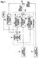
- Fig. 1 is a block diagram showing the configuration of a first embodiment of a means for estimating the charged state of a battery according to the present invention.
- a current sensing means 10 detects the charging/discharging current of the battery.
- a voltage sensing means 12 detects the voltage of the battery.
- the value of the charging/discharging current detected by the current sensing means 10 is integrated in a pseudo-SOC estimating means 14 and added to a predetermined initial SOC value of the battery in order to estimate a pseudo-SOC as a temporary SOC value.
- the initial SOC value is 100% if the battery is fully charged, or is given as an estimated SOC value at the end of the previous use of the battery.
- an electromotive force estimating means 16 estimates the voltage of the battery corresponding to the pseudo-SOC.
- the battery voltage estimated by the electromotive force estimating means 16 is an estimated open voltage Voc of the battery.
- the open voltage Voc is estimated by, for example, using a predetermined map of SOC and open voltage for each battery, and determining the open voltage Voc corresponding to the pseudo-SOC supplied from the pseudo-SOC estimating means 14.
- a voltage change estimating means 18 estimates a voltage change caused by internal resistance of the battery from the value of the charging/discharging current of the battery detected by the current sensing means 10.
- Vr represents the voltage change caused by the internal resistance estimated by the voltage change estimating means 18.
- the internal resistance r of the battery is predetermined for each battery.
- the current value Ib is a value of the charging/discharging current detected by the current sensing means 10.
- a dynamic voltage change estimating means 20 estimates a voltage change of the battery caused by a change in the charging/discharging current of the battery.
- the dynamic voltage change estimating means 20 estimates a transient voltage change Vdyn of the battery based on the above state equation.
- the coefficient matrixes A, B, and C are determined for each battery from measurements of each battery's characteristics.
- the pseudo-SOC (SOCp) is an output value of the pseudo-SOC estimating means 14.
- the SOC correction calculating means 26 calculates the second and third terms of the above equation, i.e., a component proportionate to the difference between the estimated voltage Vest and the measured voltage Vmes (Vmes-Vest) determined by the comparator 24, and a component proportionate to the integrated value of such a difference.
- Coefficients Kp, Ki are predetermined from the battery characteristics. As indicated in the equation, each component calculated by the SOC correction calculating means 26 is added by the adder 28 to the output value SOCp of the pseudo-SOC estimating means 14, whereby the estimation value of the SOC of the battery is provided.
- the present invention utilizes the battery model to estimate the battery voltage by estimating the electromotive force of the battery from the pseudo-SOC determined by the method similar to the conventional method, while estimating the voltage change caused by the internal resistance of the battery voltage and the dynamic voltage change caused by the change in the charging/discharging current, and summing up these estimated values.
- the battery model estimates the battery voltage Vest by considering the pseudo-SOC and the change in state of the battery. Then, the pseudo-SOC is corrected so that the estimated voltage vest is equal to the actually measured battery voltage Vmes, thereby estimating the SOC of the battery.
- the correction of the SOC is carried out by considering not only the integrated charging/discharging current but also the changes in the internal resistance and the battery state, so that the estimation accuracy of the battery SOC can be improved significantly.
- the pseudo-SOC is corrected so that the estimated voltage Vest is equal to the actually measured battery voltage Vmes, it is possible to provide the correct SOC value quickly even if a large error exists in the initial SOC value.
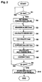
- Fig. 2 is a flowchart showing the SOC estimating operation carried out by the means for estimating the charged state of the battery of Fig. 1.
- a pseudo-SOC value is set by the pseudo-SOC estimating means 14 as a temporary value representative of the state of charge of the battery, which is determined depending on whether or not the battery is in full charge, or otherwise determined from the estimated SOC value at the end of the last use of the battery (S2).
- the current sensing means 10 and the voltage sensing means 12 measure a charging/discharging current value Ib and a real voltage Vmes of the battery, respectively (S3).
- the pseudo-SOC estimating means 14 calculates the pseudo-SOC (S4). From the pseudo-SOC estimated by the pseudo-SOC estimating means 14, the electromotive force estimating means 16 estimates the open voltage Voc of the battery. From the charging/discharging current value Ib of the battery detected by the current sensing means 10, the voltage change estimating means 18 estimates the voltage change Vr caused by the internal resistance. The dynamic voltage change estimating means 20 estimates the voltage change Vdyn caused by the change in the charging/discharging current of the battery. Then, the estimated voltage Vest of the battery is calculated by summing the open voltage Voc, the voltage change Vr caused by the internal resistance, and the voltage change Vdyn caused by the change in the charging/discharging current of the battery (S5).
- the comparator 24 compares the estimated voltage Vest calculated as above with the measured voltage Vmes of the battery actually measured by the voltage sensing means 12 (S6). Based on the difference between Vmes and Vest derived from the comparison in the comparator 24, the SOC correction calculating means 26 calculates the correction of the pseudo-SOC estimated by the pseudo-SOC estimating means 14 (S7).
- the adder 28 adds the SOC correction calculated by the SOC correction calculating means 26 to the pseudo-SOC to correct the pseudo-SOC, to calculate the estimated SOC value (S8).
- the estimated SOC value of the battery at that point of time is stored in a non-volatile memory and will be used as the next initial pseudo-SOC value (S10).
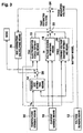
- Fig. 3 is a block diagram showing the configuration of a second embodiment of the means for estimating the charged state of a battery according to the present invention.
- elements corresponding to those already described for Fig. 1 are denoted with corresponding reference numbers and their description will not be repeated.
- the configuration of Fig. 3 is characterized in that when the pseudo-SOC estimating means 14, the electromotive force estimating means 16, the voltage change estimating means 18, and the dynamic voltage change estimating means 20 carry out respective estimating operations, correction is carried out in consideration of a battery temperature Tb.
- this embodiment includes a temperature sensing means 30 for sensing a temperature of the battery, and the output value thereof is supplied to the pseudo-SOC estimating means 14, the electromotive force estimating means 16, the voltage change estimating means 18, and the dynamic voltage change estimating means 20, respectively.
- Fig. 4 is a block diagram showing the configuration of a third embodiment of the means for estimating the charged state of a battery according to the present invention.
- elements corresponding to those already described for Figs. 1 or 3 are denoted with corresponding reference numbers and their description will not be repeated.
- the configuration of Fig. 4 is characterized in that, when respective estimating operations are carried out in the battery model, correction is carried out corresponding to the estimated SOC value obtained by correcting the pseudo-SOC.
- the SOC of the battery is estimated by adding the SOC correction calculated by the SOC correction calculating means 26 to the pseudo-SOC by the adder 28, and the estimated SOC value is supplied to the electromotive force estimating means 16, the voltage change estimating means 18, and the dynamic voltage change estimating means 20, respectively, to correct estimating operations of these means.
- the change in battery characteristics caused by the change of SOC can be considered, such that the SOC estimation is carried out more accurately.
- the nature of correction carried out by individual estimating means is predetermined according to the battery characteristics, as in the second embodiment.
- Fig. 5 shows a modified implementation of the dynamic voltage change estimating means 20 used in a fourth embodiment of the means for estimating the charged state of a battery according to the present invention. It should be noted that the elements which are not illustrated in Fig. 5 are the same as those in the first, second, and third embodiments illustrated in Figs. 1, 3, and 4, respectively.
- the dynamic voltage change estimating means 20 is configured as a neural network.
- the neural network consists of an input layer 32, an intermediate layer 34, and an output layer 36.
- Each unit of the input layer 32 being coupled with all or part of the units of the intermediate layer 34, and all or part of the units of the intermediate layer 34 are then coupled with each unit of the output layer 36.
- the neural network shown in Fig. 5 is characterized in that this is a recurrent type network including a feedback path 38 from the output layer 36 to the input layer 32.
- Vdyn is expressed in terms of two time steps [k] and [k+1].
- the dynamic voltage change Vdyn [k+1] is expressed as the function f with Ib [k],SOC [k] , Tb [k] , and Vdyn [k] being variables.
- the type of the function f is determined by training the neural network.
- the input layer 32 of the neural network receives a feedback term Vdyn [k] at a given time step k, the charging/discharging current value Ib [k] detected by the current sensing means 10, the estimated SOC [k] obtained by adding the SOC correction calculated by the SOC correction calculating means 2 6 to the pseudo-SOC in the adder 28, and the battery temperature Tb [k] sensed by the temperature sensing means 30.
- the output layer 36 outputs the voltage change Vdyn [k+1] at a time step [k+1] via the predetermined intermediate layer 34. If the neural network of this embodiment is incorporated in the means for estimating the charged state of a battery illustrated in Figs. 1 and 3, respectively, only the charging/discharging current value Ib [k] is input in Fig.1, and the charging/discharging current value Ib [k] and the battery temperature Tb [k] are input in Fig. 3.
- the neural network is trained by supplying teacher data having a non-linear characteristic based on the chemical reactions within the battery to the input layer 32.
- the size of the couplings among individual units is changed, so that the neural network has couplings capable of responding to the non-linear characteristic of the battery.
- the dynamic voltage change Vdyn [k+1] is, as mentioned above, determined by the function f using the individual input data to the neural network as variables and, since this is not a simple linear function, the non-linear characteristic of the battery can be expressed more faithfully.
- the dynamic voltage change estimating means 20 of this embodiment having a particularly strong non-linear characteristic in the battery is thus formed by the recurrent type neural network capable of sufficiently responding to the non-linear characteristic of the battery, such that a more accurate battery model can be provided and the charged state of a battery can be accurately estimated.
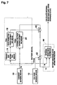
- Fig. 7 is a block diagram showing the configuration for implementing a method for estimating the degraded state of battery according to the present invention.
- the state of decay of the battery appears as a change in the internal resistance, so that it is possible to estimate the state of decay of the battery by monitoring the internal resistance.
- the current sensing means 10 measures the charging/discharging current value Ib of the battery
- the voltage sensing means 12 measures the voltage of the battery (Vmes).
- the pseudo-SOC estimating means 14 integrates the charging/discharging current value Ib detected by the current sensing means 10, and adds it to the predetermined initial SOC value of the battery to provide the estimated SOC value or the pseudo-SOC.
- the initial SOC value may be determined, for example, by assuming the full-charge state of the battery be 100%.
- the electromotive force estimating means 16 estimates the battery voltage corresponding to the pseudo-SOC.
- the battery voltage estimated by the electromotive force estimating means 16 is the estimated open voltage Voc of the battery.
- Such an open voltage Voc is estimated, for example, by using a predetermined map of SOC and open voltage for each battery and determining the open voltage Voc corresponding to the pseudo-SOC supplied from the pseudo-SOC estimating means 14.
- the voltage of the battery is changed dynamically in accordance with changes in the charging/discharging current of the battery.
- the dynamic voltage change estimating means 20 estimates such a dynamic voltage change of the battery.
- the dynamic voltage change estimating means 20 estimates the transient voltage change Vdyn of the battery according to the above state equation.
- Each coefficient matrix A, B and C is predetermined for each battery by measuring its characteristics.
- this embodiment utilizes the battery model consisting of the pseudo-SOC estimating means 14, the electromotive force estimating means 16, and the dynamic voltage change estimating means 20 to estimate the open voltage Voc and the dynamic voltage change Vdyn of the battery based on the charging/discharging current value Ib of the battery detected by the current sensing means 10.
- Vr is thus determined by subtracting, from the measured voltage Vmes of the battery, the electromotive force or the open voltage Voc of the battery corresponding to the SOC at the time of the measurement, and the dynamic voltage change Vdyn based on the change in the charging/discharging current, so that Vr represents the voltage change caused by the internal resistance of the battery.
- this embodiment estimates the internal resistance by removing the voltage change of the battery caused by the change in SOC and the change in the charging/discharging current of the battery to only extract the voltage change caused by the internal resistance, so that the estimation of the internal resistance of the battery can be carried out with high accuracy. As a result, the state of decay of the battery can be known correctly. By estimating the changes in the internal resistance of the battery, it is also possible to detect other abnormal conditions, such as short circuit of the battery or breaking of wires.
- a typical least-squares method requires a large memory during calculation because all of the past current values have to be summed up and stored. It is, therefore, preferable to adopt the weighted least-squares method incorporating exponential weights (forgetting factor ⁇ :0 ⁇ 1).
- R is the internal resistance of the battery
- I is the measured current
- Vr is the measured current - the open circuit voltage - the dynamic voltage change
- n is the nth sample
- ⁇ is an exponential weight (0 ⁇ 1, forgetting factor).
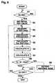
- Fig. 8 is a flowchart showing the steps of a method for estimating the state of decay of battery according to the present invention.
- whether or not the ignition switch is turned on is checked (S1) and, upon turning on of the switch, the initial SOC value is set in the pseudo-SOC estimating means 14 (S2).
- the current sensing means 10 and the voltage sensing means 12 measure the charging/discharging current value Ib and the voltage Vmes, respectively (S3).
- the pseudo-SOC estimating means 14 integrates the charging/discharging current value Ib and adds the integrated value to the initial SOC value set in S2 in order to calculate the pseudo-SOC (S4).
- the electromotive force estimating means 16 calculates the open voltage Voc of the battery by using the pseudo-SOC.
- the dynamic voltage change estimating means 20 calculates the dynamic voltage change Vdyn of the battery based on the change in the charging/discharging current (S5).
- Vr is calculated according to the above equation (3) (S6).
- the internal resistance R of the battery is calculated according to the above equation (4) (S7).
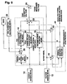
- Fig. 9 is a block diagram showing the configuration of a means for estimating the SOC of the battery by using the internal resistance R, the open voltage Voc, and the dynamic voltage change Vdyn of the battery estimated above.
- elements corresponding to those already described for Fig. 7 are denoted with corresponding reference numbers and their description will not be repeated. .
- the internal resistance of a battery which was previously measured, such as at the time of production, for example, is corrected according to the estimated internal resistance R of the battery estimated by the battery state of decay estimating section 44. This is useful for constantly maintaining the internal resistance of the battery at a correct value in the battery model.
- the voltage change estimating means 18 estimates the voltage change caused by the internal resistance of the battery.
- VR represents the voltage change caused by the internal resistance R estimated by the voltage estimating means 18.
- the current value Ib is the charging/discharging current value detected by the current sensing means 10.
- the battery model is modeled after the actual battery by the pseudo-SOC estimating means 14, the electromotive force estimating means 16, the dynamic voltage change estimating means 20, the voltage change estimating means 18, and the adder 22.
- the comparator 24 compares the estimated battery voltage Vest with the actually measured voltage Vmes detected by the voltage sensing means 12, and supplies the obtained difference between the two voltages to the SOC correction calculating means 26 which, in turn, calculates the correction of SOC so that the estimated voltage Vest is equal to the measured voltage Vmes.
- the estimated value of the battery SOC is given by SOCp + Kp(Vmes - Vest) + Ki ⁇ (Vmes - Vest) dt where SOCp is the pseudo-SOC, and Kp and Ki are coefficients.
- the pseudo-SOC (SOCp) is the output value of the pseudo-SOC estimating means 14.
- the SOC correction estimating means 26 calculates the second and third terms of the above expression, that is, a component proportionate to the difference (Vmes - Vest) between the estimated voltage Vest and the measured voltage Vmes determined by the comparator 24, and a component proportionate to the integrated value of the difference. Coefficients Kp, Ki are predetermined from the battery characteristics.
- the adder 28 adds respective components calculated by the SOC correction calculating means 26 to the output value SOCp of the pseudo-SOC estimating means 14 to thereby provide the estimated SOC value of the battery.
- this embodiment utilizes the battery model to estimate the battery voltage by estimating the electromotive force of the battery from the pseudo-SOC, the voltage change caused by the internal resistance of the battery, and the dynamic voltage change caused by the change in the charging/discharging current, and summing up these input values.
- the battery model is used to estimate the battery voltage Vest by considering the pseudo-SOC and the change in battery state.
- the pseudo-SOC is corrected so that the estimated voltage Vest is equal to the battery voltage Vmes actually measured to thereby estimate the SOC of the battery.
- the SOC is corrected by considering the changes in the internal resistance and the battery state in addition to the integrated charging/discharging current.
- the estimation accuracy of the battery SOC is significantly improved. Because the internal resistance R of the battery used here is a corrected value corrected by the battery state of decay estimating section, the estimation accuracy of the SOC is further improved.
- the present invention estimates the SOC of a battery by considering the dynamic state change of the battery, such as the change in the charging/discharging current of the battery, whereby it is possible to estimate the SOC with high accuracy even for the battery of a hybrid vehicle or the like where charging/discharging is switched and repeated in short cycles.
- the estimation accuracy of estimating the charged state of the battery can be further improved.
- the accuracy of the estimation of the internal resistance can be improved by removing the change in the electromotive force caused by the change in the SOC and the dynamic voltage change caused by the change in the charging/discharging current from the measured battery voltage, and determining the voltage change only caused by the internal resistance of the battery. It is therefore possible to accurately estimate the internal resistance. As a result, the actual state of decay of the battery can be known.
Applications Claiming Priority (5)
| Application Number | Priority Date | Filing Date | Title |
|---|---|---|---|
| JP14682898 | 1998-05-28 | ||
| JP14682898 | 1998-05-28 | ||
| JP16039398 | 1998-06-09 | ||
| JP16039398 | 1998-06-09 | ||
| PCT/JP1999/002728 WO1999061929A1 (en) | 1998-05-28 | 1999-05-25 | Means for estimating charged state of battery and method for estimating degraded state of battery |
Publications (3)
| Publication Number | Publication Date |
|---|---|
| EP1081499A1 true EP1081499A1 (de) | 2001-03-07 |
| EP1081499A4 EP1081499A4 (de) | 2001-12-12 |
| EP1081499B1 EP1081499B1 (de) | 2003-07-09 |
Family
ID=26477541
Family Applications (1)
| Application Number | Title | Priority Date | Filing Date |
|---|---|---|---|
| EP99921254A Revoked EP1081499B1 (de) | 1998-05-28 | 1999-05-25 | Vorrichtung zum schätzen des ladungszustands einer batterie und verfahren zum schätzen des abnutzungszustands einer batterie |
Country Status (9)
| Country | Link |
|---|---|
| US (1) | US6285163B1 (de) |
| EP (1) | EP1081499B1 (de) |
| JP (1) | JP3873623B2 (de) |
| KR (1) | KR100425352B1 (de) |
| CN (1) | CN1199050C (de) |
| CA (1) | CA2333619C (de) |
| DE (1) | DE69909472T2 (de) |
| ES (1) | ES2197638T3 (de) |
| WO (1) | WO1999061929A1 (de) |
Cited By (27)
| Publication number | Priority date | Publication date | Assignee | Title |
|---|---|---|---|---|
| WO2002071087A1 (de) * | 2001-03-08 | 2002-09-12 | Daimlerchrysler Ag | Verfahren und anordnung zur bestimmung der pufferwirkung einer batterie |
| EP1283425A1 (de) * | 2001-08-10 | 2003-02-12 | Peugeot Citroen Automobiles SA | Verfahren zur Abschätzung von Hochleistungsbatterie-parametern eines Elektromotorfahrzeugs |
| EP1314992A2 (de) * | 2001-10-30 | 2003-05-28 | Yamaha Hatsudoki Kabushiki Kaisha | Verfahren und Vorrichtung zur Ladezustandskontrolle einer Kraftfahrzeugbatterie |
| EP1319956A1 (de) * | 2001-12-14 | 2003-06-18 | Peugeot Citroen Automobiles SA | System für die festlegung des Ladezustandes und der Spannung einer elektrischen Speicherbatterie, inbesondere für ein Kraftfahrzeug |
| GB2386709A (en) * | 2002-03-18 | 2003-09-24 | Ching Chuen Chan | A neural network for estimating battery residual capacity in an electric vehicle |
| EP1351068A3 (de) * | 2002-04-02 | 2003-10-15 | The Raymond Corporation | Ladezustandsanzeige einer Batterie |
| WO2004008166A1 (ja) | 2002-07-12 | 2004-01-22 | Toyota Jidosha Kabushiki Kaisha | バッテリ充電状態推定装置 |
| WO2006072501A1 (de) * | 2004-12-29 | 2006-07-13 | Robert Bosch Gmbh | Verfahren zur bestimmung des innenwiderstandes einer batterie |
| EP1801604A2 (de) * | 2005-12-21 | 2007-06-27 | Samsung SDI Co., Ltd. | Verfahren zur Kompensation des Ladungszustandes einer Batterie und damit ausgestattetes Batterieverwaltungssystem |
| EP1801606A2 (de) | 2005-12-22 | 2007-06-27 | Samsung SDI Co., Ltd. | Verfahren zum Ausgleich des Ladezustands einer Batterie, Batterieverwaltungssystem damit und Hybridfahrzeug mit dem Batterieverwaltungssystem |
| EP1801605A1 (de) * | 2005-12-22 | 2007-06-27 | Samsung SDI Co., Ltd. | Verfahren zur Ladezustandsregelung für eine Batterie und Batterieverwaltungssystem damit |
| EP1801947A3 (de) * | 2005-12-21 | 2007-07-11 | Samsung SDI Co., Ltd. | Verfahren zur Kompensation der Batterieladungszustand und Batterieverwaltungssystem |
| FR2897161A1 (fr) * | 2006-02-09 | 2007-08-10 | Peugeot Citroen Automobiles Sa | Systeme de recalage de l'information d'etat de charge d'une batterie de vehicule automobile |
| EP1914559A2 (de) * | 2006-10-16 | 2008-04-23 | Samsung SDI Co., Ltd. | Batterieverwaltungssystem und Verfahren zu dessen Ansteuerung |
| EP2102672A1 (de) * | 2006-12-06 | 2009-09-23 | ITI Scotland Limited | Batteriemanagementsystem |
| US7634369B2 (en) | 2006-10-12 | 2009-12-15 | Samsung Sdi Co., Ltd. | Battery management system (BMS) and driving method thereof |
| US7652449B2 (en) | 2006-09-26 | 2010-01-26 | Samsung Sdi Co., Ltd. | Battery management system and driving method thereof |
| US7656124B2 (en) | 2005-07-29 | 2010-02-02 | Samsung Sdi Co., Ltd. | Battery management system and driving method thereof |
| US7679325B2 (en) | 2005-04-07 | 2010-03-16 | Samsung Sdi Co., Ltd. | Battery management system and driving method for cutting off and coupling battery module from/to external device |
| US7880432B2 (en) | 2005-10-20 | 2011-02-01 | Samsung Sdi Co., Ltd. | Battery management system and battery management method |
| US7928736B2 (en) | 2005-10-20 | 2011-04-19 | Samsung Sdi Co., Ltd. | Method of estimating state of charge for battery and battery management system using the same |
| US8013573B2 (en) | 2007-03-19 | 2011-09-06 | Samsung Sdi Co., Ltd. | Battery pack that provides precise voltage measurements of batteries when safety switch is present |
| FR2973517A1 (fr) * | 2011-04-04 | 2012-10-05 | Peugeot Citroen Automobiles Sa | Dispositif d'estimation de variable(s) d'etat d'une cellule d'une batterie multicellulaire, en fonction au moins du courant qui la traverse |
| CN102754303A (zh) * | 2010-02-25 | 2012-10-24 | 三洋电机株式会社 | 蓄电池控制装置、蓄电池系统、电动车辆、充电控制装置、充电器、移动体、电源系统、电力贮存装置及电源装置 |
| US8796986B2 (en) | 2006-11-01 | 2014-08-05 | Samsung Sdi Co., Ltd. | Battery management system and driving method thereof |
| GB2532343A (en) * | 2014-10-17 | 2016-05-18 | Jaguar Land Rover Ltd | Battery condition monitoring |
| EP3647802A4 (de) * | 2017-06-29 | 2021-03-24 | Kabushiki Kaisha Toshiba | Vorrichtung zur restmengenschätzung bei speicherbatterien, verfahren zur restmengenschätzung bei speicherbatterien und programm |
Families Citing this family (103)
| Publication number | Priority date | Publication date | Assignee | Title |
|---|---|---|---|---|
| US6928371B1 (en) * | 2000-02-08 | 2005-08-09 | Paul T. Roshau | Monitoring system of VRLA battery capacitance |
| DE10056969A1 (de) * | 2000-11-17 | 2002-05-23 | Bosch Gmbh Robert | Verfahren und Anordnung zur Bestimmung des Ladezustandes einer Batterie |
| JP3817141B2 (ja) * | 2000-12-05 | 2006-08-30 | 矢崎総業株式会社 | 車両用バッテリの劣化度判定方法及び装置 |
| DE10235008B4 (de) * | 2001-08-03 | 2005-02-24 | Yazaki Corp. | Verfahren und Einheit zum Berechnen des Degradationsgrades für eine Batterie |
| US6677729B2 (en) * | 2001-08-03 | 2004-01-13 | Yazaki Corporation | Method and unit for computing voltage drop divided along factors for battery |
| JP3613216B2 (ja) * | 2001-09-18 | 2005-01-26 | 日産自動車株式会社 | ハイブリッド車両の制御装置 |
| JP4097182B2 (ja) * | 2001-12-27 | 2008-06-11 | パナソニックEvエナジー株式会社 | 二次電池の分極電圧推定方法、二次電池の残存容量推定方法および装置、並びに電池パックシステム |
| FR2835923B1 (fr) * | 2002-02-13 | 2004-05-14 | Peugeot Citroen Automobiles Sa | Systeme de determination de l'etat de charge d'une batterie, notamment pour vehicule automobile |
| JP4157317B2 (ja) * | 2002-04-10 | 2008-10-01 | 株式会社日立製作所 | 状態検知装置及びこれを用いた各種装置 |
| JP3714333B2 (ja) * | 2003-02-28 | 2005-11-09 | 日産自動車株式会社 | 二次電池の入出力可能電力推定装置 |
| JP4597501B2 (ja) * | 2003-10-01 | 2010-12-15 | プライムアースEvエナジー株式会社 | 二次電池の残存容量推定方法および装置 |
| JP4103781B2 (ja) * | 2003-11-19 | 2008-06-18 | トヨタ自動車株式会社 | 負荷駆動回路における異常監視装置 |
| US7321220B2 (en) * | 2003-11-20 | 2008-01-22 | Lg Chem, Ltd. | Method for calculating power capability of battery packs using advanced cell model predictive techniques |
| ES2247896B1 (es) * | 2003-12-03 | 2007-06-01 | Universitat Politecnica De Catalunya | Dispositivo y metodo para la medida dinamica del nivel de energia y el estado de salud de baterias de plomo-acido. |
| KR100624365B1 (ko) * | 2004-12-01 | 2006-09-18 | 주식회사 파워트론 | 축전지셀 단자전압 및 내부 임피던스 측정 회로 |
| US7583059B2 (en) * | 2003-12-18 | 2009-09-01 | Lg Chem, Ltd. | Apparatus and method for estimating state of charge of battery using neural network |
| DE102004004280B4 (de) * | 2004-01-27 | 2014-06-12 | Audi Ag | Verfahren zur Diagnose von Batterien |
| US8618805B2 (en) * | 2004-03-25 | 2013-12-31 | 02Micro, Inc. | Battery pack with a battery protection circuit |
| US7180268B2 (en) * | 2004-03-25 | 2007-02-20 | O2Micro International Limited | Circuits capable of trickle precharge and/or trickle discharge |
| MXPA06011388A (es) * | 2004-04-06 | 2007-04-25 | Cobasys Llc | Estimador del estado de carga de bateria. |
| US7095211B2 (en) * | 2004-04-16 | 2006-08-22 | O2Micro International Limited | Battery gas gauge |
| US7233128B2 (en) * | 2004-07-30 | 2007-06-19 | Ford Global Technologies, Llc | Calculation of state of charge offset using a closed integral method |
| JP4778431B2 (ja) * | 2004-08-25 | 2011-09-21 | 日本電気株式会社 | 内部インピーダンス検出装置、内部インピーダンス検出方法、劣化度検出装置および劣化度検出方法 |
| US7209841B2 (en) * | 2004-11-15 | 2007-04-24 | Cobasys, Llc | Maximum and minimum power limit calculator for batteries and battery subpacks |
| JP4571000B2 (ja) * | 2005-03-29 | 2010-10-27 | 富士重工業株式会社 | 蓄電デバイスの残存容量演算装置 |
| JP4587306B2 (ja) * | 2005-04-20 | 2010-11-24 | 株式会社デンソー | 二次電池の残存容量演算方法 |
| KR100793616B1 (ko) * | 2005-06-13 | 2008-01-10 | 주식회사 엘지화학 | 배터리 잔존량 추정 장치 및 방법 |
| US7589532B2 (en) * | 2005-08-23 | 2009-09-15 | Lg Chem, Ltd. | System and method for estimating a state vector associated with a battery |
| KR101256073B1 (ko) * | 2005-10-11 | 2013-04-18 | 삼성에스디아이 주식회사 | 배터리의 soc 추정 방법 및 이를 이용한 배터리 관리시스템 |
| JP2007121030A (ja) * | 2005-10-26 | 2007-05-17 | Denso Corp | 車両用蓄電装置の内部状態検出装置 |
| US7446504B2 (en) * | 2005-11-10 | 2008-11-04 | Lg Chem, Ltd. | System, method, and article of manufacture for determining an estimated battery state vector |
| US7723957B2 (en) * | 2005-11-30 | 2010-05-25 | Lg Chem, Ltd. | System, method, and article of manufacture for determining an estimated battery parameter vector |
| JP4984527B2 (ja) * | 2005-12-27 | 2012-07-25 | トヨタ自動車株式会社 | 二次電池の充電状態推定装置および充電状態推定方法 |
| KR100814811B1 (ko) * | 2006-02-03 | 2008-03-19 | 삼성에스디아이 주식회사 | 배터리 관리 시스템 및 이의 잔존용량 리셋 방법 |
| JP4967362B2 (ja) | 2006-02-09 | 2012-07-04 | トヨタ自動車株式会社 | 二次電池の残存容量推定装置 |
| EP2138857A4 (de) | 2007-04-19 | 2011-08-03 | Panasonic Ev Energy Co Ltd | Vorrichtung und verfahren zur erkennung des ladestatus einer elektrischen speichervorrichtung |
| US20080259551A1 (en) * | 2007-04-20 | 2008-10-23 | Gotive A.S. | Modular computing device |
| DE102007034044B4 (de) * | 2007-07-20 | 2019-07-04 | Bayerische Motoren Werke Aktiengesellschaft | Verfahren zur Ermittlung einer aktuell verfügbaren Energiemenge eines Energiespeichermoduls |
| DE102007036165A1 (de) * | 2007-08-02 | 2009-02-05 | BSH Bosch und Siemens Hausgeräte GmbH | Verfahren und Schaltungsanordnung zum Bestimmen des Ladezustands eines Akkumulators eines akkumulatorbetriebenen Gerätes, insbesondere eines akkumulatorbetriebenen selbstfahrenden Staubsammelroboters |
| JP4771176B2 (ja) * | 2007-08-27 | 2011-09-14 | 株式会社デンソー | バッテリの充放電制御装置 |
| US7768233B2 (en) * | 2007-10-04 | 2010-08-03 | Gm Global Technology Operations, Inc. | Dynamically adaptive method for determining the state of charge of a battery |
| JP4494453B2 (ja) * | 2007-11-13 | 2010-06-30 | トヨタ自動車株式会社 | 二次電池の制御装置および制御方法 |
| US7994755B2 (en) | 2008-01-30 | 2011-08-09 | Lg Chem, Ltd. | System, method, and article of manufacture for determining an estimated battery cell module state |
| JP4893653B2 (ja) * | 2008-02-19 | 2012-03-07 | トヨタ自動車株式会社 | 車両、二次電池の充電状態推定方法および車両の制御方法 |
| JP5155701B2 (ja) * | 2008-03-12 | 2013-03-06 | 富士重工業株式会社 | 車両用電源装置 |
| JP4513882B2 (ja) * | 2008-03-21 | 2010-07-28 | トヨタ自動車株式会社 | ハイブリッド車およびその制御方法 |
| US8305034B2 (en) * | 2008-07-23 | 2012-11-06 | Lear Corporation | Battery monitoring system |
| JP5448408B2 (ja) * | 2008-10-15 | 2014-03-19 | 三菱重工業株式会社 | 二次電池制御システム |
| US8159228B2 (en) * | 2008-12-18 | 2012-04-17 | Lear Corporation | Method for determining battery internal resistance |
| JP4772137B2 (ja) * | 2009-06-02 | 2011-09-14 | トヨタ自動車株式会社 | バッテリ使用機器の制御装置 |
| US8207706B2 (en) * | 2009-08-04 | 2012-06-26 | Honda Motor Co., Ltd. | Method of estimating battery state of charge |
| JP5496612B2 (ja) * | 2009-11-11 | 2014-05-21 | 三洋電機株式会社 | 電池の充放電可能電流演算方法及び電源装置並びにこれを備える車両 |
| KR101399388B1 (ko) * | 2010-01-18 | 2014-05-27 | 에스케이이노베이션 주식회사 | 배터리의 수명 예측 장치 및 방법 |
| US9722334B2 (en) | 2010-04-07 | 2017-08-01 | Black & Decker Inc. | Power tool with light unit |
| US8341449B2 (en) | 2010-04-16 | 2012-12-25 | Lg Chem, Ltd. | Battery management system and method for transferring data within the battery management system |
| WO2011133863A2 (en) | 2010-04-22 | 2011-10-27 | Enerdel, Inc. | Monitoring of battery state of charge |
| CN102859377B (zh) * | 2010-04-26 | 2014-11-05 | 丰田自动车株式会社 | 蓄电元件的劣化推定装置和劣化推定方法 |
| JP5511951B2 (ja) * | 2010-06-07 | 2014-06-04 | 三菱電機株式会社 | 充電状態推定装置 |
| KR20110134019A (ko) * | 2010-06-08 | 2011-12-14 | 현대자동차주식회사 | 차량용 배터리의 셀 열화 진단 방법 |
| US20120101753A1 (en) * | 2010-10-20 | 2012-04-26 | Gm Global Technology Operations, Inc. | Adaptive slowly-varying current detection |
| US20120179435A1 (en) * | 2011-01-10 | 2012-07-12 | Ford Global Technologies, Llc | Method For Determining A Power Capability For A Battery |
| FR2970820B1 (fr) * | 2011-01-24 | 2013-01-04 | Renault Sa | Procede de gestion de la charge d'une batterie rechargeable d'un vehicule automobile |
| US8449998B2 (en) | 2011-04-25 | 2013-05-28 | Lg Chem, Ltd. | Battery system and method for increasing an operational life of a battery cell |
| US8974928B2 (en) | 2011-06-30 | 2015-03-10 | Lg Chem, Ltd. | Heating system for a battery module and method of heating the battery module |
| US8974929B2 (en) | 2011-06-30 | 2015-03-10 | Lg Chem, Ltd. | Heating system for a battery module and method of heating the battery module |
| US8993136B2 (en) | 2011-06-30 | 2015-03-31 | Lg Chem, Ltd. | Heating system for a battery module and method of heating the battery module |
| US8859119B2 (en) | 2011-06-30 | 2014-10-14 | Lg Chem, Ltd. | Heating system for a battery module and method of heating the battery module |
| JP5924516B2 (ja) * | 2011-07-28 | 2016-05-25 | 横河電機株式会社 | 電池インピーダンス測定装置 |
| CN102288921A (zh) * | 2011-09-05 | 2011-12-21 | 中国科学院上海硅酸盐研究所 | 电池批量检测方法及系统 |
| WO2013072927A2 (en) * | 2011-09-30 | 2013-05-23 | Kpit Cummins Infosystems Limited | System and method for battery monitoring |
| CN102590680A (zh) * | 2012-02-29 | 2012-07-18 | 广东步步高电子工业有限公司 | 一种可模拟真电池特性的智能电源 |
| JP5803767B2 (ja) * | 2012-03-22 | 2015-11-04 | 株式会社デンソー | 2次電池の充電相当量算出装置 |
| US9018913B2 (en) | 2012-05-18 | 2015-04-28 | Caterpillar Inc. | System for determining battery impedance |
| JP5596083B2 (ja) * | 2012-06-26 | 2014-09-24 | Imv株式会社 | リチウムイオン二次電池の劣化診断装置 |
| TWI461718B (zh) * | 2012-08-01 | 2014-11-21 | Univ Ishou | Battery power test method |
| AT512003A3 (de) * | 2013-01-23 | 2014-05-15 | Avl List Gmbh | Verfahren zur Ermittlung eines regelungstechnischen Beobachters für den SoC |
| US9244129B2 (en) * | 2013-01-29 | 2016-01-26 | Mitsubishi Electronic Research Laboratories, Inc. | Method for estimating a state of charge of batteries |
| JP5994680B2 (ja) * | 2013-02-27 | 2016-09-21 | 株式会社豊田自動織機 | 電池残容量推定方法及び装置 |
| US9897659B2 (en) | 2013-03-28 | 2018-02-20 | Sanyo Electric Co., Ltd. | Secondary battery charge status estimation device and secondary battery charge status estimation method |
| US9770997B2 (en) * | 2013-06-11 | 2017-09-26 | Ford Global Technologies, Llc | Detection of imbalance across multiple battery cells measured by the same voltage sensor |
| DE102013106083B4 (de) * | 2013-06-12 | 2022-02-10 | Infineon Technologies Ag | Verfahren und Vorrichtung zum Bestimmen eines Parameters eines Modells einer technischen Einrichtung |
| JP2015010962A (ja) * | 2013-06-28 | 2015-01-19 | 古河電池株式会社 | 蓄電池の劣化判定方法および蓄電池の劣化判定装置 |
| WO2015162967A1 (ja) * | 2014-04-23 | 2015-10-29 | 三菱電機株式会社 | 電池残量推定装置および電池残量推定方法 |
| KR101692104B1 (ko) * | 2014-05-07 | 2017-01-02 | 주식회사 엘지화학 | 배터리 잔존 용량 산출 장치 및 방법 |
| US20160001670A1 (en) * | 2014-07-01 | 2016-01-07 | Ford Global Technologies, Llc | System and method for battery management |
| DE102014220913B4 (de) * | 2014-10-15 | 2019-06-06 | Volkswagen Aktiengesellschaft | Verfahren und Vorrichtung zur Bestimmung einer Widerstandsänderung einer Energiespeichereinrichtung und Fahrzeug |
| CN105223512A (zh) * | 2015-09-11 | 2016-01-06 | 华晨汽车集团控股有限公司 | 基于电池特性的动态矫正剩余电量的方法 |
| DE102016002698A1 (de) * | 2016-03-04 | 2017-09-07 | Audi Ag | Steuervorrichtung und Verfahren zum Steuern eines Gleichspannungswandlers eines Kraftfahrzeugs |
| KR20180085165A (ko) * | 2017-01-18 | 2018-07-26 | 삼성전자주식회사 | 배터리 관리 방법 및 장치 |
| JP7116886B2 (ja) * | 2017-02-20 | 2022-08-12 | 株式会社Gsユアサ | 状態推定装置 |
| US10399452B2 (en) | 2017-07-10 | 2019-09-03 | Ford Global Technologies, Llc | Battery charge management system |
| KR102179684B1 (ko) | 2017-09-29 | 2020-11-17 | 주식회사 엘지화학 | 배터리 팩의 soh를 산출하는 장치 및 방법 |
| JP6927009B2 (ja) * | 2017-12-12 | 2021-08-25 | トヨタ自動車株式会社 | 二次電池システムおよび二次電池のsoc推定方法 |
| JP7006311B2 (ja) | 2018-01-29 | 2022-01-24 | トヨタ自動車株式会社 | 電動車両及び電動車両の制御方法 |
| US20200103468A1 (en) * | 2018-09-27 | 2020-04-02 | Denso Ten Limited | Soc estimation apparatus |
| KR102259643B1 (ko) * | 2019-10-17 | 2021-06-02 | 경북대학교 산학협력단 | 배터리의 상태 모니터링 방법 및 장치 |
| KR102303478B1 (ko) * | 2019-11-21 | 2021-09-17 | 연세대학교 산학협력단 | 드론용 배터리 가용 용량 제공 장치 및 방법 |
| US11262411B2 (en) * | 2019-12-18 | 2022-03-01 | Boe Technology Group Co., Ltd. | Terminal apparatus, and method and device for determining battery state of charge |
| WO2022101769A1 (en) * | 2020-11-13 | 2022-05-19 | Kpit Technologies Limited | A hybrid system and method for estimating state of charge of a battery |
| CA3205991A1 (en) * | 2020-12-30 | 2022-07-07 | Baxter International Inc. | System and method for generating battery alarms in infusion devices |
| DE102021201857A1 (de) * | 2021-02-26 | 2022-09-01 | Siemens Mobility GmbH | Schätzeinrichtungen und Verfahren zum Schätzen des Betriebszustands einer Batterie |
| JP2023027446A (ja) | 2021-08-17 | 2023-03-02 | 矢崎総業株式会社 | 蓄電池制御装置、蓄電システム、及び蓄電池制御方法 |
| KR102549349B1 (ko) * | 2021-09-28 | 2023-06-30 | (주)이투솔루션즈 | 배터리의 상태 정보를 획득하는 방법 및 디바이스 |
Citations (3)
| Publication number | Priority date | Publication date | Assignee | Title |
|---|---|---|---|---|
| US5381096A (en) * | 1992-04-09 | 1995-01-10 | Hirzel; Edgar A. | Method and apparatus for measuring the state-of-charge of a battery system |
| EP0711016A2 (de) * | 1994-11-04 | 1996-05-08 | Mitsubishi Denki Kabushiki Kaisha | Parametermessverfahren, Verfahren und Vorrichtung zur Steuerung des Ladens und Entladens und Verfahren zur Bestimmung des Lebensendes für Sekundärbatterien und Energiespeichergerät damit |
| JPH1020003A (ja) * | 1996-07-01 | 1998-01-23 | Kyushu Denki Seizo Kk | モデルベース電池残存容量計 |
Family Cites Families (13)
| Publication number | Priority date | Publication date | Assignee | Title |
|---|---|---|---|---|
| DE59002764D1 (de) | 1989-05-12 | 1993-10-21 | Fraunhofer Ges Forschung | Verfahren zur bestimmung von physikalischen grössen von wiederaufladbaren elektrischen energiespeichern. |
| JP2530074B2 (ja) * | 1991-11-19 | 1996-09-04 | 四国電力株式会社 | 鉛蓄電池の残存容量推定装置 |
| JPH0816691B2 (ja) * | 1991-11-19 | 1996-02-21 | 四国電力株式会社 | 鉛蓄電池の開路電圧推定装置 |
| JPH0620723A (ja) | 1992-07-07 | 1994-01-28 | Fujitsu Ltd | 二次電池残量表示装置および表示方法 |
| JP3550160B2 (ja) * | 1992-11-06 | 2004-08-04 | 株式会社キューキ | 電池の残存容量計 |
| JP3540437B2 (ja) | 1995-06-05 | 2004-07-07 | 本田技研工業株式会社 | 電池状態判別装置 |
| JPH0933622A (ja) * | 1995-07-21 | 1997-02-07 | Tokyo R & D:Kk | 電池残存容量計 |
| JPH0996665A (ja) | 1995-09-29 | 1997-04-08 | Nippon Soken Inc | 電池残存容量計 |
| US5808445A (en) * | 1995-12-06 | 1998-09-15 | The University Of Virginia Patent Foundation | Method for monitoring remaining battery capacity |
| JP3520886B2 (ja) | 1996-03-08 | 2004-04-19 | サンケン電気株式会社 | 二次電池の状態判定方法 |
| US6051976A (en) * | 1996-07-29 | 2000-04-18 | Midtronics, Inc. | Method and apparatus for auditing a battery test |
| JPH1092475A (ja) * | 1996-09-19 | 1998-04-10 | Nissan Motor Co Ltd | 非水系二次電池の特性演算装置 |
| JPH10104324A (ja) | 1996-09-27 | 1998-04-24 | Mitsuoka Denki Seisakusho:Kk | 電池残量推定装置 |
-
1999
- 1999-05-25 ES ES99921254T patent/ES2197638T3/es not_active Expired - Lifetime
- 1999-05-25 EP EP99921254A patent/EP1081499B1/de not_active Revoked
- 1999-05-25 CN CNB998092282A patent/CN1199050C/zh not_active Expired - Fee Related
- 1999-05-25 JP JP2000551271A patent/JP3873623B2/ja not_active Expired - Lifetime
- 1999-05-25 KR KR10-2000-7013362A patent/KR100425352B1/ko not_active IP Right Cessation
- 1999-05-25 WO PCT/JP1999/002728 patent/WO1999061929A1/ja active IP Right Grant
- 1999-05-25 DE DE69909472T patent/DE69909472T2/de not_active Revoked
- 1999-05-25 CA CA002333619A patent/CA2333619C/en not_active Expired - Fee Related
- 1999-05-25 US US09/701,067 patent/US6285163B1/en not_active Expired - Lifetime
Patent Citations (3)
| Publication number | Priority date | Publication date | Assignee | Title |
|---|---|---|---|---|
| US5381096A (en) * | 1992-04-09 | 1995-01-10 | Hirzel; Edgar A. | Method and apparatus for measuring the state-of-charge of a battery system |
| EP0711016A2 (de) * | 1994-11-04 | 1996-05-08 | Mitsubishi Denki Kabushiki Kaisha | Parametermessverfahren, Verfahren und Vorrichtung zur Steuerung des Ladens und Entladens und Verfahren zur Bestimmung des Lebensendes für Sekundärbatterien und Energiespeichergerät damit |
| JPH1020003A (ja) * | 1996-07-01 | 1998-01-23 | Kyushu Denki Seizo Kk | モデルベース電池残存容量計 |
Non-Patent Citations (2)
| Title |
|---|
| PATENT ABSTRACTS OF JAPAN vol. 1998, no. 5, 30 April 1998 (1998-04-30) & JP 10 020003 A (KYUSHU DENKI SEIZO), 23 January 1998 (1998-01-23) * |
| See also references of WO9961929A1 * |
Cited By (46)
| Publication number | Priority date | Publication date | Assignee | Title |
|---|---|---|---|---|
| US7199588B2 (en) | 2001-03-08 | 2007-04-03 | Daimlerchrysler Ag | Method and system for determining the buffer action of a battery |
| WO2002071087A1 (de) * | 2001-03-08 | 2002-09-12 | Daimlerchrysler Ag | Verfahren und anordnung zur bestimmung der pufferwirkung einer batterie |
| EP1283425A1 (de) * | 2001-08-10 | 2003-02-12 | Peugeot Citroen Automobiles SA | Verfahren zur Abschätzung von Hochleistungsbatterie-parametern eines Elektromotorfahrzeugs |
| FR2828562A1 (fr) * | 2001-08-10 | 2003-02-14 | Peugeot Citroen Automobiles Sa | Procede d'estimation de parametres de la batterie de puissance d'un vehicule a moteur electrique |
| US6788069B2 (en) | 2001-08-10 | 2004-09-07 | Peugeot Citroen Automobiles Sa | Method for calculating the parameters of the power battery of an electric motor vehicle |
| EP1314992A2 (de) * | 2001-10-30 | 2003-05-28 | Yamaha Hatsudoki Kabushiki Kaisha | Verfahren und Vorrichtung zur Ladezustandskontrolle einer Kraftfahrzeugbatterie |
| EP1319956A1 (de) * | 2001-12-14 | 2003-06-18 | Peugeot Citroen Automobiles SA | System für die festlegung des Ladezustandes und der Spannung einer elektrischen Speicherbatterie, inbesondere für ein Kraftfahrzeug |
| FR2833711A1 (fr) * | 2001-12-14 | 2003-06-20 | Peugeot Citroen Automobiles Sa | Systeme de determination de l'etat de charge et de la tension d'une batterie de stockage d'energie electrique, notamment pour vehicule automobile |
| GB2386709A (en) * | 2002-03-18 | 2003-09-24 | Ching Chuen Chan | A neural network for estimating battery residual capacity in an electric vehicle |
| GB2386709B (en) * | 2002-03-18 | 2004-03-17 | Ching Chuen Chan | Battery residual capacity estimation for electric vehicles |
| EP1351068A3 (de) * | 2002-04-02 | 2003-10-15 | The Raymond Corporation | Ladezustandsanzeige einer Batterie |
| EP1548453A4 (de) * | 2002-07-12 | 2009-01-14 | Toyota Motor Co Ltd | SCHüTZER FüR DEN BATTERIELADUNGSZUSTAND |
| WO2004008166A1 (ja) | 2002-07-12 | 2004-01-22 | Toyota Jidosha Kabushiki Kaisha | バッテリ充電状態推定装置 |
| EP1548453A1 (de) * | 2002-07-12 | 2005-06-29 | Toyota Jidosha Kabushiki Kaisha | SCHüTZER FüR DEN BATTERIELADUNGSZUSTAND |
| WO2006072501A1 (de) * | 2004-12-29 | 2006-07-13 | Robert Bosch Gmbh | Verfahren zur bestimmung des innenwiderstandes einer batterie |
| US7902793B2 (en) | 2004-12-29 | 2011-03-08 | Robert Bosch Gmbh | Method for determining the internal resistance of a battery |
| US7679325B2 (en) | 2005-04-07 | 2010-03-16 | Samsung Sdi Co., Ltd. | Battery management system and driving method for cutting off and coupling battery module from/to external device |
| US7656124B2 (en) | 2005-07-29 | 2010-02-02 | Samsung Sdi Co., Ltd. | Battery management system and driving method thereof |
| US7880432B2 (en) | 2005-10-20 | 2011-02-01 | Samsung Sdi Co., Ltd. | Battery management system and battery management method |
| US7928736B2 (en) | 2005-10-20 | 2011-04-19 | Samsung Sdi Co., Ltd. | Method of estimating state of charge for battery and battery management system using the same |
| US7649338B2 (en) | 2005-12-21 | 2010-01-19 | Samsung Sdi Co., Ltd. | Method for compensating state of charge of battery and battery management system using the same |
| US7728555B2 (en) | 2005-12-21 | 2010-06-01 | Samsung Sdi Co., Ltd. | Method for compensating state of charge of battery and battery management system using the same |
| EP1801604A2 (de) * | 2005-12-21 | 2007-06-27 | Samsung SDI Co., Ltd. | Verfahren zur Kompensation des Ladungszustandes einer Batterie und damit ausgestattetes Batterieverwaltungssystem |
| EP1801604A3 (de) * | 2005-12-21 | 2007-07-11 | Samsung SDI Co., Ltd. | Verfahren zur Kompensation des Ladungszustandes einer Batterie und damit ausgestattetes Batterieverwaltungssystem |
| EP1801947A3 (de) * | 2005-12-21 | 2007-07-11 | Samsung SDI Co., Ltd. | Verfahren zur Kompensation der Batterieladungszustand und Batterieverwaltungssystem |
| EP1801605A1 (de) * | 2005-12-22 | 2007-06-27 | Samsung SDI Co., Ltd. | Verfahren zur Ladezustandsregelung für eine Batterie und Batterieverwaltungssystem damit |
| EP1801606A2 (de) | 2005-12-22 | 2007-06-27 | Samsung SDI Co., Ltd. | Verfahren zum Ausgleich des Ladezustands einer Batterie, Batterieverwaltungssystem damit und Hybridfahrzeug mit dem Batterieverwaltungssystem |
| EP1801606A3 (de) * | 2005-12-22 | 2011-06-22 | Samsung SDI Co., Ltd. | Verfahren zum Ausgleich des Ladezustands einer Batterie, Batterieverwaltungssystem damit und Hybridfahrzeug mit dem Batterieverwaltungssystem |
| US7982433B2 (en) | 2005-12-22 | 2011-07-19 | Samsung Sdi Co., Ltd. | Method of adjusting SOC for battery and battery management system using the same |
| FR2897161A1 (fr) * | 2006-02-09 | 2007-08-10 | Peugeot Citroen Automobiles Sa | Systeme de recalage de l'information d'etat de charge d'une batterie de vehicule automobile |
| US7652449B2 (en) | 2006-09-26 | 2010-01-26 | Samsung Sdi Co., Ltd. | Battery management system and driving method thereof |
| US7634369B2 (en) | 2006-10-12 | 2009-12-15 | Samsung Sdi Co., Ltd. | Battery management system (BMS) and driving method thereof |
| US7680613B2 (en) | 2006-10-16 | 2010-03-16 | Samsung Sdi Co., Ltd. | Battery management system (BMS) and driving method thereof |
| EP1914559A3 (de) * | 2006-10-16 | 2008-05-14 | Samsung SDI Co., Ltd. | Batterieverwaltungssystem und Verfahren zu dessen Ansteuerung |
| EP1914559A2 (de) * | 2006-10-16 | 2008-04-23 | Samsung SDI Co., Ltd. | Batterieverwaltungssystem und Verfahren zu dessen Ansteuerung |
| CN101165963B (zh) * | 2006-10-16 | 2012-03-21 | 三星Sdi株式会社 | 电池管理系统及其驱动方法 |
| US8796986B2 (en) | 2006-11-01 | 2014-08-05 | Samsung Sdi Co., Ltd. | Battery management system and driving method thereof |
| EP2102672A1 (de) * | 2006-12-06 | 2009-09-23 | ITI Scotland Limited | Batteriemanagementsystem |
| US8013573B2 (en) | 2007-03-19 | 2011-09-06 | Samsung Sdi Co., Ltd. | Battery pack that provides precise voltage measurements of batteries when safety switch is present |
| CN102754303A (zh) * | 2010-02-25 | 2012-10-24 | 三洋电机株式会社 | 蓄电池控制装置、蓄电池系统、电动车辆、充电控制装置、充电器、移动体、电源系统、电力贮存装置及电源装置 |
| FR2973517A1 (fr) * | 2011-04-04 | 2012-10-05 | Peugeot Citroen Automobiles Sa | Dispositif d'estimation de variable(s) d'etat d'une cellule d'une batterie multicellulaire, en fonction au moins du courant qui la traverse |
| GB2532343A (en) * | 2014-10-17 | 2016-05-18 | Jaguar Land Rover Ltd | Battery condition monitoring |
| GB2532343B (en) * | 2014-10-17 | 2017-03-01 | Jaguar Land Rover Ltd | Battery condition monitoring |
| EP3207388B1 (de) * | 2014-10-17 | 2021-03-31 | Jaguar Land Rover Limited | Batteriezustandsüberwachung |
| EP3647802A4 (de) * | 2017-06-29 | 2021-03-24 | Kabushiki Kaisha Toshiba | Vorrichtung zur restmengenschätzung bei speicherbatterien, verfahren zur restmengenschätzung bei speicherbatterien und programm |
| US11221370B2 (en) | 2017-06-29 | 2022-01-11 | Kabushiki Kaisha Toshiba | Remaining battery energy estimation device, remaining battery energy estimation method, and storage medium |
Also Published As
| Publication number | Publication date |
|---|---|
| KR100425352B1 (ko) | 2004-03-31 |
| JP3873623B2 (ja) | 2007-01-24 |
| CN1199050C (zh) | 2005-04-27 |
| ES2197638T3 (es) | 2004-01-01 |
| CN1311860A (zh) | 2001-09-05 |
| CA2333619A1 (en) | 1999-12-02 |
| EP1081499A4 (de) | 2001-12-12 |
| KR20010043872A (ko) | 2001-05-25 |
| WO1999061929A1 (en) | 1999-12-02 |
| DE69909472D1 (de) | 2003-08-14 |
| DE69909472T2 (de) | 2004-05-27 |
| EP1081499B1 (de) | 2003-07-09 |
| CA2333619C (en) | 2003-08-05 |
| US6285163B1 (en) | 2001-09-04 |
Similar Documents
| Publication | Publication Date | Title |
|---|---|---|
| EP1081499B1 (de) | Vorrichtung zum schätzen des ladungszustands einer batterie und verfahren zum schätzen des abnutzungszustands einer batterie | |
| US6534954B1 (en) | Method and apparatus for a battery state of charge estimator | |
| RU2328753C2 (ru) | Устройство и способ для оценки уровня заряженности батареи с использованием нейронной сети | |
| JP5058814B2 (ja) | バッテリーの状態及びパラメーターの推定システム及び方法 | |
| US8099180B2 (en) | State and parameter estimator having integral and differential components for electrical energy accumulators | |
| JP4793332B2 (ja) | 電池充電状態の推定方法 | |
| US5479085A (en) | Method and apparatus for measuring residual capacity of an electric-vehicle battery | |
| US9091739B2 (en) | Method and apparatus for determining deterioration of secondary battery, and power supply system therewith | |
| JP3209457B2 (ja) | バッテリの残容量検出方法 | |
| US5539318A (en) | Residual capacity meter for electric car battery | |
| KR100818520B1 (ko) | 전기화학셀(cell)의 현재 상태와 현재 파라미터를추정하는 장치, 방법 및 시스템 및 기록매체 | |
| KR101195515B1 (ko) | 전원장치용 상태검지장치, 전원장치 및 전원장치에사용되는 초기 특성 추출장치 | |
| EP1469321A1 (de) | Vorrichtung und Verfahren zur Überwachung des Ladezustands einer Batterie | |
| EP2700964A2 (de) | Batteriezustandsschätzungssystem, Batteriesteuersystem, Batteriesystem, und Verfahren zur Schätzung des Batteriezustands | |
| EP1422804A2 (de) | Einrichtung und Verfahren zur Ladeleistungsschätzung einer Sekundärbatterie | |
| JP3006298B2 (ja) | 電池残存容量計 | |
| JP3752888B2 (ja) | 電池状態検出装置 | |
| CN116113837A (zh) | 用于估计电池的荷电状态的方法 | |
| WO2020026509A1 (ja) | 電池状態推定装置、電池制御装置 | |
| KR100878123B1 (ko) | 배터리 상태 및 파라미터 추정 시스템 및 방법 | |
| JP2001085071A (ja) | 組電池の温度検出装置および温度検出方法 | |
| US5736835A (en) | Battery pack, a charger, and a method of detecting the remaining capacity of secondary cells | |
| JP2006220617A (ja) | 車両用蓄電装置の内部状態検出方式 | |
| JPH0933622A (ja) | 電池残存容量計 | |
| CN113125983B (zh) | 电池容量估算方法和系统 |
Legal Events
| Date | Code | Title | Description |
|---|---|---|---|
| PUAI | Public reference made under article 153(3) epc to a published international application that has entered the european phase |
Free format text: ORIGINAL CODE: 0009012 |
|
| 17P | Request for examination filed |
Effective date: 20001128 |
|
| AK | Designated contracting states |
Kind code of ref document: A1 Designated state(s): DE ES FR GB IT |
|
| A4 | Supplementary search report drawn up and despatched |
Effective date: 20011029 |
|
| AK | Designated contracting states |
Kind code of ref document: A4 Designated state(s): DE ES FR GB IT |
|
| GRAH | Despatch of communication of intention to grant a patent |
Free format text: ORIGINAL CODE: EPIDOS IGRA |
|
| GRAH | Despatch of communication of intention to grant a patent |
Free format text: ORIGINAL CODE: EPIDOS IGRA |
|
| GRAA | (expected) grant |
Free format text: ORIGINAL CODE: 0009210 |
|
| AK | Designated contracting states |
Designated state(s): DE ES FR GB IT |
|
| REG | Reference to a national code |
Ref country code: GB Ref legal event code: FG4D |
|
| REF | Corresponds to: |
Ref document number: 69909472 Country of ref document: DE Date of ref document: 20030814 Kind code of ref document: P |
|
| REG | Reference to a national code |
Ref country code: ES Ref legal event code: FG2A Ref document number: 2197638 Country of ref document: ES Kind code of ref document: T3 |
|
| ET | Fr: translation filed | ||
| PLBI | Opposition filed |
Free format text: ORIGINAL CODE: 0009260 |
|
| PLAX | Notice of opposition and request to file observation + time limit sent |
Free format text: ORIGINAL CODE: EPIDOSNOBS2 |
|
| 26 | Opposition filed |
Opponent name: DAIMLERCHRYSLER AG Effective date: 20040413 |
|
| PLBB | Reply of patent proprietor to notice(s) of opposition received |
Free format text: ORIGINAL CODE: EPIDOSNOBS3 |
|
| PLAY | Examination report in opposition despatched + time limit |
Free format text: ORIGINAL CODE: EPIDOSNORE2 |
|
| PLAH | Information related to despatch of examination report in opposition + time limit modified |
Free format text: ORIGINAL CODE: EPIDOSCORE2 |
|
| PLBC | Reply to examination report in opposition received |
Free format text: ORIGINAL CODE: EPIDOSNORE3 |
|
| PLAB | Opposition data, opponent's data or that of the opponent's representative modified |
Free format text: ORIGINAL CODE: 0009299OPPO |
|
| R26 | Opposition filed (corrected) |
Opponent name: DAIMLERCHRYSLER AG Effective date: 20040413 |
|
| PLAY | Examination report in opposition despatched + time limit |
Free format text: ORIGINAL CODE: EPIDOSNORE2 |
|
| RTI2 | Title (correction) |
Free format text: MEANS FOR ESTIMATING CHARGED STATE OF BATTERY |
|
| PLAP | Information related to despatch of examination report in opposition + time limit deleted |
Free format text: ORIGINAL CODE: EPIDOSDORE2 |
|
| APBP | Date of receipt of notice of appeal recorded |
Free format text: ORIGINAL CODE: EPIDOSNNOA2O |
|
| APBP | Date of receipt of notice of appeal recorded |
Free format text: ORIGINAL CODE: EPIDOSNNOA2O |
|
| APBQ | Date of receipt of statement of grounds of appeal recorded |
Free format text: ORIGINAL CODE: EPIDOSNNOA3O |
|
| APAH | Appeal reference modified |
Free format text: ORIGINAL CODE: EPIDOSCREFNO |
|
| PGFP | Annual fee paid to national office [announced via postgrant information from national office to epo] |
Ref country code: ES Payment date: 20090609 Year of fee payment: 11 |
|
| PGFP | Annual fee paid to national office [announced via postgrant information from national office to epo] |
Ref country code: IT Payment date: 20090520 Year of fee payment: 11 Ref country code: FR Payment date: 20090515 Year of fee payment: 11 Ref country code: DE Payment date: 20090527 Year of fee payment: 11 |
|
| PLAB | Opposition data, opponent's data or that of the opponent's representative modified |
Free format text: ORIGINAL CODE: 0009299OPPO |
|
| R26 | Opposition filed (corrected) |
Opponent name: DAIMLERCHRYSLER AG Effective date: 20040413 |
|
| APBU | Appeal procedure closed |
Free format text: ORIGINAL CODE: EPIDOSNNOA9O |
|
| RDAF | Communication despatched that patent is revoked |
Free format text: ORIGINAL CODE: EPIDOSNREV1 |
|
| RDAG | Patent revoked |
Free format text: ORIGINAL CODE: 0009271 |
|
| STAA | Information on the status of an ep patent application or granted ep patent |
Free format text: STATUS: PATENT REVOKED |
|
| PGFP | Annual fee paid to national office [announced via postgrant information from national office to epo] |
Ref country code: GB Payment date: 20090520 Year of fee payment: 11 |
|
| 27W | Patent revoked |
Effective date: 20091013 |
|
| GBPR | Gb: patent revoked under art. 102 of the ep convention designating the uk as contracting state |
Effective date: 20091013 |