EP1080314B1 - Kupplung und kraftstoffförderpumpe mit kupplung - Google Patents
Kupplung und kraftstoffförderpumpe mit kupplung Download PDFInfo
- Publication number
- EP1080314B1 EP1080314B1 EP00920380A EP00920380A EP1080314B1 EP 1080314 B1 EP1080314 B1 EP 1080314B1 EP 00920380 A EP00920380 A EP 00920380A EP 00920380 A EP00920380 A EP 00920380A EP 1080314 B1 EP1080314 B1 EP 1080314B1
- Authority
- EP
- European Patent Office
- Prior art keywords
- coupling
- coupling part
- drive shaft
- rotatable
- fuel delivery
- Prior art date
- Legal status (The legal status is an assumption and is not a legal conclusion. Google has not performed a legal analysis and makes no representation as to the accuracy of the status listed.)
- Expired - Lifetime
Links
- 230000008878 coupling Effects 0.000 title claims description 59
- 238000010168 coupling process Methods 0.000 title claims description 59
- 238000005859 coupling reaction Methods 0.000 title claims description 59
- 239000000446 fuel Substances 0.000 title claims description 19
- 230000000295 complement effect Effects 0.000 claims description 4
- 230000002093 peripheral effect Effects 0.000 claims description 2
- 230000005540 biological transmission Effects 0.000 description 3
- 238000001816 cooling Methods 0.000 description 2
- 238000009434 installation Methods 0.000 description 2
- 230000010354 integration Effects 0.000 description 2
- 238000005461 lubrication Methods 0.000 description 2
- 238000005086 pumping Methods 0.000 description 2
- 239000000243 solution Substances 0.000 description 2
- 238000002485 combustion reaction Methods 0.000 description 1
- 238000013016 damping Methods 0.000 description 1
- 238000005516 engineering process Methods 0.000 description 1
- 238000001746 injection moulding Methods 0.000 description 1
- 239000000314 lubricant Substances 0.000 description 1
- 230000001050 lubricating effect Effects 0.000 description 1
- 238000004519 manufacturing process Methods 0.000 description 1
- 239000000463 material Substances 0.000 description 1
- 210000001331 nose Anatomy 0.000 description 1
- 239000004033 plastic Substances 0.000 description 1
- 238000004080 punching Methods 0.000 description 1
- 239000013585 weight reducing agent Substances 0.000 description 1
Images
Classifications
-
- F—MECHANICAL ENGINEERING; LIGHTING; HEATING; WEAPONS; BLASTING
- F16—ENGINEERING ELEMENTS AND UNITS; GENERAL MEASURES FOR PRODUCING AND MAINTAINING EFFECTIVE FUNCTIONING OF MACHINES OR INSTALLATIONS; THERMAL INSULATION IN GENERAL
- F16D—COUPLINGS FOR TRANSMITTING ROTATION; CLUTCHES; BRAKES
- F16D1/00—Couplings for rigidly connecting two coaxial shafts or other movable machine elements
- F16D1/06—Couplings for rigidly connecting two coaxial shafts or other movable machine elements for attachment of a member on a shaft or on a shaft-end
- F16D1/08—Couplings for rigidly connecting two coaxial shafts or other movable machine elements for attachment of a member on a shaft or on a shaft-end with clamping hub; with hub and longitudinal key
-
- F—MECHANICAL ENGINEERING; LIGHTING; HEATING; WEAPONS; BLASTING
- F02—COMBUSTION ENGINES; HOT-GAS OR COMBUSTION-PRODUCT ENGINE PLANTS
- F02B—INTERNAL-COMBUSTION PISTON ENGINES; COMBUSTION ENGINES IN GENERAL
- F02B67/00—Engines characterised by the arrangement of auxiliary apparatus not being otherwise provided for, e.g. the apparatus having different functions; Driving auxiliary apparatus from engines, not otherwise provided for
- F02B67/04—Engines characterised by the arrangement of auxiliary apparatus not being otherwise provided for, e.g. the apparatus having different functions; Driving auxiliary apparatus from engines, not otherwise provided for of mechanically-driven auxiliary apparatus
-
- F—MECHANICAL ENGINEERING; LIGHTING; HEATING; WEAPONS; BLASTING
- F02—COMBUSTION ENGINES; HOT-GAS OR COMBUSTION-PRODUCT ENGINE PLANTS
- F02M—SUPPLYING COMBUSTION ENGINES IN GENERAL WITH COMBUSTIBLE MIXTURES OR CONSTITUENTS THEREOF
- F02M37/00—Apparatus or systems for feeding liquid fuel from storage containers to carburettors or fuel-injection apparatus; Arrangements for purifying liquid fuel specially adapted for, or arranged on, internal-combustion engines
- F02M37/04—Feeding by means of driven pumps
- F02M37/06—Feeding by means of driven pumps mechanically driven
-
- F—MECHANICAL ENGINEERING; LIGHTING; HEATING; WEAPONS; BLASTING
- F04—POSITIVE - DISPLACEMENT MACHINES FOR LIQUIDS; PUMPS FOR LIQUIDS OR ELASTIC FLUIDS
- F04C—ROTARY-PISTON, OR OSCILLATING-PISTON, POSITIVE-DISPLACEMENT MACHINES FOR LIQUIDS; ROTARY-PISTON, OR OSCILLATING-PISTON, POSITIVE-DISPLACEMENT PUMPS
- F04C15/00—Component parts, details or accessories of machines, pumps or pumping installations, not provided for in groups F04C2/00 - F04C14/00
- F04C15/0057—Driving elements, brakes, couplings, transmission specially adapted for machines or pumps
- F04C15/0061—Means for transmitting movement from the prime mover to driven parts of the pump, e.g. clutches, couplings, transmissions
- F04C15/0073—Couplings between rotors and input or output shafts acting by interengaging or mating parts, i.e. positive coupling of rotor and shaft
-
- F—MECHANICAL ENGINEERING; LIGHTING; HEATING; WEAPONS; BLASTING
- F16—ENGINEERING ELEMENTS AND UNITS; GENERAL MEASURES FOR PRODUCING AND MAINTAINING EFFECTIVE FUNCTIONING OF MACHINES OR INSTALLATIONS; THERMAL INSULATION IN GENERAL
- F16D—COUPLINGS FOR TRANSMITTING ROTATION; CLUTCHES; BRAKES
- F16D1/00—Couplings for rigidly connecting two coaxial shafts or other movable machine elements
- F16D1/06—Couplings for rigidly connecting two coaxial shafts or other movable machine elements for attachment of a member on a shaft or on a shaft-end
- F16D1/08—Couplings for rigidly connecting two coaxial shafts or other movable machine elements for attachment of a member on a shaft or on a shaft-end with clamping hub; with hub and longitudinal key
- F16D1/0829—Couplings for rigidly connecting two coaxial shafts or other movable machine elements for attachment of a member on a shaft or on a shaft-end with clamping hub; with hub and longitudinal key with radial loading of both hub and shaft by an intermediate ring or sleeve
-
- F—MECHANICAL ENGINEERING; LIGHTING; HEATING; WEAPONS; BLASTING
- F16—ENGINEERING ELEMENTS AND UNITS; GENERAL MEASURES FOR PRODUCING AND MAINTAINING EFFECTIVE FUNCTIONING OF MACHINES OR INSTALLATIONS; THERMAL INSULATION IN GENERAL
- F16D—COUPLINGS FOR TRANSMITTING ROTATION; CLUTCHES; BRAKES
- F16D1/00—Couplings for rigidly connecting two coaxial shafts or other movable machine elements
- F16D1/06—Couplings for rigidly connecting two coaxial shafts or other movable machine elements for attachment of a member on a shaft or on a shaft-end
- F16D2001/062—Couplings for rigidly connecting two coaxial shafts or other movable machine elements for attachment of a member on a shaft or on a shaft-end characterised by adaptors where hub bores being larger than the shaft
-
- F—MECHANICAL ENGINEERING; LIGHTING; HEATING; WEAPONS; BLASTING
- F16—ENGINEERING ELEMENTS AND UNITS; GENERAL MEASURES FOR PRODUCING AND MAINTAINING EFFECTIVE FUNCTIONING OF MACHINES OR INSTALLATIONS; THERMAL INSULATION IN GENERAL
- F16D—COUPLINGS FOR TRANSMITTING ROTATION; CLUTCHES; BRAKES
- F16D1/00—Couplings for rigidly connecting two coaxial shafts or other movable machine elements
- F16D1/10—Quick-acting couplings in which the parts are connected by simply bringing them together axially
- F16D2001/102—Quick-acting couplings in which the parts are connected by simply bringing them together axially the torque is transmitted via polygon shaped connections
-
- Y—GENERAL TAGGING OF NEW TECHNOLOGICAL DEVELOPMENTS; GENERAL TAGGING OF CROSS-SECTIONAL TECHNOLOGIES SPANNING OVER SEVERAL SECTIONS OF THE IPC; TECHNICAL SUBJECTS COVERED BY FORMER USPC CROSS-REFERENCE ART COLLECTIONS [XRACs] AND DIGESTS
- Y10—TECHNICAL SUBJECTS COVERED BY FORMER USPC
- Y10T—TECHNICAL SUBJECTS COVERED BY FORMER US CLASSIFICATION
- Y10T403/00—Joints and connections
- Y10T403/70—Interfitted members
- Y10T403/7047—Radially interposed shim or bushing
Definitions
- the invention relates to a coupling according to the preamble of claim 1.
- the coupling of two rotatable bodies can e.g. take place by a Buchschlitzkupplung, which is also referred to as Buchin- or Oldhamkupplung.
- Couplings according to the cross-slit principle serve to transmit movements. They are mainly used for drive coupling in non-aligned axes.
- the cross recess principle is based on two coupling halves (drive and output) and an intermediate disc as a coupling part.
- On the two coupling halves guide rails or grooves are formed which are perpendicular to each other.
- At the intermediate disc complementary guide grooves or guide rails are formed. The transmission of the rotational movement is true to angle, the intermediate disc slides on the guides of the coupling halves.
- the known cross-slot principle is based on a series connection of a drive element, an intermediate disc and an output element.
- the transmission of torque takes place in two levels. This results in a relatively large height.
- the tilting tendency of the washer has proved to be disadvantageous.
- the occurrence of a large surface pressure in the guides leads at high speeds to a strong frictional heat development and high wear.
- the object of the invention is to further develop the known clutches and a fuel delivery pump with such a coupling with a small height, especially in relation to the transmittable torque and the life.
- the clutch according to the invention and the fuel delivery pump according to the invention should be inexpensive to produce and easy to assemble.
- connection shafts and Verlier Klien be eliminated, which are required in conventional cross-slotted couplings. This leads to a reduction in the number of parts required
- a pre-centering of the rotatable body is possible with the help of the integrated coupling part.
- the coupling part may be formed one or more parts.
- the coupling part has the shape of a disc in which a central slot is recessed with approximately flat or slightly convex side surfaces, which serves for receiving a rotatable body, in particular a drive shaft, and are formed on the four tapered lugs, wherein in the other rotatable body, in particular a gear, a central recess is provided, whose contour is formed complementary to the contour of the disc, the object of the invention is solved.
- the coupling is arranged outside the functional space.
- the inventive design of the coupling it is possible to arrange the clutch within the functional space.
- the functional space may be e.g. to act around the housing of a fuel pump.
- a particular embodiment of the invention is characterized in that the coupling part is formed asymmetrically in itself. This provides the advantage that a wrong installation of the coupling part is prevented. This simplifies assembly.
- Another particular embodiment of the invention is characterized in that the contact surfaces between the coupling part and the rotatable bodies are formed crowned. As a result, the surface pressure occurring during operation is reduced and the lubricating properties are improved. The occurring friction and consequently the wear are minimized.
- a fuel delivery pump having two in a pumping chamber mutually engaged rotatable gears, the fuel from a reservoir connected to a suction space along a between the end faces of the gears and the peripheral wall of the Pumping chamber formed conveying channel in a pressure chamber, wherein one of the gears is driven by a drive shaft
- the above-described object is achieved in that the drive shaft is coupled by a previously described coupling with the driven gear.
- a fuel delivery pump is known, for example, from DE 196 25 488.
- the drive of the fuel delivery pump takes place, for example, via the camshaft of an internal combustion engine.
- the fuel delivery pump may also be coupled to a high pressure pump.
- the fuel delivery pump according to the invention provides the following advantages: Coupling of the gear to the drive shaft in one plane, fewer interfaces, a lower tendency to tilt, lower tilting moments, lower friction, lower height, fewer parts, optimized material use, weight reduction, integration of the coupling part in the driven gear , no additional support or guide for the coupling part necessary, integrated lubrication, integrated cooling, cost-effective and efficient production in sintered or plastic injection molding or punching technology, pre-centering during assembly possible, improved damping, no incorrect assembly of the coupling part by asymmetric geometry, left and right rotation with the same transfer behavior, left and right rotation possible with different transfer characteristics, reduced surface pressure due to convex or concave contact geometry and captive protection eliminated by module ink gration.
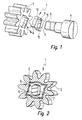
- FIG. 1 an embodiment of a coupling according to the invention is designated as a whole by 1.
- a gear 2 is with Help a coupling part 3 coupled to a drive shaft 4.
- a coupling part 3 coupled to a drive shaft 4.
- two flats 6 and 7 are formed.
- the end 5 of the drive shaft 4 is received in a slot 8 with two approximately flat or slightly convex side surfaces 6 'and 7' ( Figure 4), which is recessed in the coupling part 3.
- the coupling part 3 has essentially the shape of a cuboidal disc, on which four pointed noses 9, 10, 11 and 12 are formed in a star shape.
- the surfaces between the lugs 9 to 12 are each slightly curved outward.
- a recess 14 is provided, whose geometry is formed complementary to the coupling part 3.
- In the center of the recess 14 may be recessed a through hole for receiving the end 5 of the drive shaft 4.
- Between the coupling part 3 and the recess 14 in the gear 2 is sufficient clearance available to ensure easy installation of the coupling 1. Due to the special geometry of the coupling part 3 and the recess 14 in the gear 2 a secure torque transmission is ensured. At the same time, axial offsets can be compensated.
- the gear 2 is in a housing 18 of a fuel delivery pump according to the invention.
- the structure and operation of the fuel delivery pump are described in DE 196 25 488.
- the housing 18 is closed by a cover 19, in which a bore for the drive shaft 4 is provided.
- a circle 16 is indicated where the drive shaft 4 is centered relative to the lid 19.
- Figure 7 it can be seen that the entire circumference 20 of the drive shaft 4 serves for centering.
- the clutch is arranged outside the housing of the fuel delivery pump. In this arrangement, an additional connecting shaft is necessary. This results in additional interfaces between the coupling and the connecting shaft and between the connecting shaft and the driven gear. For the clutch is In addition, a captive needed.
- the inventive solution a complete integration of the entire coupling system in the housing of the fuel pump is possible.
- the delivery medium contained in the housing of the fuel delivery pump is used for lubrication and cooling of the coupling according to the invention.
Landscapes
- Engineering & Computer Science (AREA)
- General Engineering & Computer Science (AREA)
- Mechanical Engineering (AREA)
- Chemical & Material Sciences (AREA)
- Combustion & Propulsion (AREA)
- Details And Applications Of Rotary Liquid Pumps (AREA)
- Rotary Pumps (AREA)
Description
- Die Erfindung betrifft eine Kupplung nach dem Oberbegriff des Anspruchs 1.
- Die Kopplung von zwei drehbaren Körpern kann z.B. durch eine Kreuzschlitzkupplung erfolgen, die auch als Kreuzscheiben- oder Oldhamkupplung bezeichnet wird. Kupplungen nach dem Kreuzschlitzprinzip dienen zur Übertragung von Bewegungen. Sie werden vorwiegend zur Antriebskopplung bei nicht fluchtenden Achsen eingesetzt.
- Das Kreuzschlitzprinzip basiert auf zwei Kupplungshälften (Antrieb und Abtrieb) und einer Zwischenscheibe als Kupplungsteil. An den beiden Kupplungshälften sind Führungsleisten oder Führungsnuten ausgebildet, die senkrecht zueinander angeordnet sind. An der Zwischenscheibe sind komplementäre Führungsnuten oder Führungsleisten ausgebildet. Die Übertragung der Drehbewegung erfolgt winkeltreu, wobei die Zwischenscheibe auf den Führungen der Kupplungshälften gleitet.
- Das bekannte Kreuzschlitzprinzip beruht auf einer Reihenschaltung von einem Antriebselement, einer Zwischenscheibe und einem Abtriebselement. Die Übertragung eines Drehmoments erfolgt in zwei Ebenen. Daraus ergibt sich eine relativ große Bauhöhe. Außerdem hat sich die Kippneigung der Zwischenscheibe als nachteilig erwiesen. Das Auftreten einer großen Flächenpressung in den Führungen führt bei hohen Drehzahlen zu einer starken Reibungswärmeentwicklung und einem hohen Verschleiß.
- Aus der EP 0 481 410 A2 ist eine Kupplung bekannt bei der ein Kupplungsteil, das einen radialen Vorsprung aufweist auf ein Wellenende eines Motors aufgeschoben wird. Dieser radiale Vorsprung wird mit einer Aussparung in einem angetriebenen Bauteil zusammen, so dass ein Drehmoment von dem Motor auf das angetriebene Bauteil übertragen werden kann. Nachteilig an dieser Lösung ist, dass ein Achsversatz und/oder ein Fluchtungsfehler bei dieser Kupplung nicht oder nur ein sehr geringem Umfang ausgeglichen werden kann, da das Kupplungsteil spielfrei in dem angetriebenen Bauteil gelagert ist.
- Bei einer aus der DE 196 25 488 A1 bekannten Kupplung, wird das Drehmoment von einer eine Welle umgebenden Nabe auf die Nabe mit Hilfe eines zwischen Welle und Nabe eingeklemmten Gummirings kraftschlüssig übertragen.
- Aufgabe der Erfindung ist es, die bekannten Kupplungen und eine Kraftstoffförderpumpe mit einer derartigen Kupplung mit einer kleinen Bauhöhe vor allem in Bezug auf das übertragbare Drehmoment und die Lebensdauer weiterzuentwickeln.. Die erfindungsgemäße Kupplung und die erfindungsgemäße Kraftstoffförderpumpe sollen kostengünstig herstellbar und einfach zu montieren sein.
- Die Aufgabe ist bei einer Kupplung nach dem Oberbegriff des Anspruchs 1, durch die kennzeichnende Merkmale des Anspruchs 1 gelöst. Dadurch können Verbindungswellen und Verliersicherungen entfallen, die bei herkömmlichen Kreuzschlitz-Kupplungen erforderlich sind. Das führt zu einer Reduzierung der Anzahl der benötigten Teile Außerdem ist mit Hilfe des integrierten Kupplungsteiles eine Vorzentrierung der drehbaren Körper möglich. Das Kupplungsteil kann ein- oder auch mehrteilig ausgebildet sein.
- Dadurch, dass das Kupplungsteil die Form einer Scheibe hat, in der ein zentrales Langloch mit annähernd ebenen oder leicht balligen Seitenflächen ausgespart ist, das zur Aufnahme des einen drehbaren Körpers, insbesondere einer Antriebswelle, dient, und an der vier spitz zulaufende Nasen ausgebildet sind, wobei in dem anderen drehbaren Körper, insbesondere einem Zahnrad, eine zentrale Aussparung vorgesehen ist, deren Kontur komplementär zu der Kontur der Scheibe ausgebildet ist, wird die der Erfindung zu Grunde liegende Aufgabe gelöst. Üblicherweise ist die Kupplung außerhalb des Funktionsraumes angeordnet. Durch die erfindungsgemäße Ausgestaltung der Kupplung ist es möglich, die Kupplung innerhalb des Funktionsraumes anzuordnen. Bei dem Funktionsraum kann es sich z.B. um das Gehäuse einer Kraftstoffförderpumpe handeln.
- Eine besondere Ausführungsart der Erfindung ist dadurch gekennzeichnet, dass das Kupplungsteil in sich asymmetrisch ausgebildet ist. Das liefert den Vorteil, dass ein falscher Einbau des Kupplungsteils verhindert wird. Dadurch wird die Montage vereinfacht.
- Eine weitere besondere Ausführungsart der Erfindung ist dadurch gekennzeichnet, dass die Kontaktflächen zwischen dem Kupplungsteil und den drehbaren Körpern ballig ausgebildet sind. Dadurch werden die im Betrieb auftretende Flächenpressung reduziert und die Schmiereigenschaften verbessert. Die auftretende Reibung und demzufolge der Verschleiß werden minimiert.
- Bei einer Kraftstoffförderpumpe mit zwei in einer Pumpkammer miteinander in Eingriff befindlichen drehbaren Zahnrädern, die Kraftstoff aus einem mit einem Vorratsraum verbundenen Ansaugraum entlang einem zwischen den Stirnflächen der Zahnräder und der Umfangswand der Pumpkammer gebildeten Förderkanal in einen Druckraum fördern, wobei eines der Zahnräder durch eine Antriebswelle angetrieben ist, ist die vorab geschilderte Aufgabe dadurch gelöst, dass die Antriebswelle durch eine vorab beschriebene Kupplung mit dem angetriebenen Zahnrad gekoppelt ist. Eine derartige Kraftstoffförderpumpe ist bspw. aus der DE 196 25 488 bekannt. Der Antrieb der Kraftstoffförderpumpe erfolgt bspw. über die Nockenwelle einer Brennkraftmaschine. Die Kraftstoffförderpumpe kann auch mit einer Hochdruckpumpe gekoppelt sein. Die erfindungsgemäße Kraftstoffförderpumpe liefert die folgenden Vorteile: Kopplung des Zahnrads mit der Antriebswelle in nur einer Ebene, weniger Schnittstellen, eine geringere Kippneigung, geringere Kippmomente, geringere Reibung, geringere Bauhöhe, weniger Teile, optimierter Werkstoffeinsatz, Gewichtsreduzierung, Integration des Kupplungsteils in das angetriebene Zahnrad, keine zusätzliche Aufnahme oder Führung für das Kupplungsteil notwendig, integrierte Schmierung, integrierte Kühlung, kostengünstige und rationelle Herstellung in Sinter- oder Kunststoffspritzgusstechnik oder Stanztechnik, Vorzentrierung bei der Montage möglich, verbesserte Dämpfung, keine Fehlmontage des Kupplungsteils durch asymmetrische Geometrie, Links- und Rechtslauf bei gleichem Übertragungsverhalten, Links- und Rechtslauf bei unterschiedlichem Übertragungsverhalten möglich, reduzierte Flächenpressung durch konvexe bzw. konkave Anlagegeometrie und Verliersicherung entfällt durch Baugruppenintegration.
- Weitere Vorteile, Merkmale und Einzelheiten der Erfindung ergeben sich aus der nachfolgenden Beschreibung, in der unter Bezugnahme auf die Zeichnung verschiedene Ausführungsbeispiele der Erfindung im Einzelnen beschrieben sind. Dabei können die in den Ansprüchen und in der Beschreibung erwähnten Merkmale jeweils einzeln für sich oder in beliebiger Kombination erfindungswesentlich sein.
- In der Zeichnung zeigt:
- Figur 1
- eine Explosionsdarstellung einer erfindungsgemäßen Kupplung;
- Figur 2
- die Kupplung aus Figur 1 im zusammengebauten Zustand;
- Figur 3
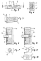
- eine Schnittdarstellung der in den Figuren 1 und 2 dargestellten Kupplung;
- Figur 4
- die Darstellung eines Schnitts entlang der Linie IV-IV in Figur 3;
- Figur 5
- eine vergrößerte Darstellung der Einzelheit x aus Figur 3;
- Figur 6
- eine Schnittdarstellung einer ersten Ausführungsform einer erfindungsgemäßen Kraftstoffförderpumpe;
- Figur 7
- einen Ausschnitt aus Figur 6 in der Seitenansicht;
- Figur 8
- eine Schnittdarstellung einer zweiten Ausführungsform einer erfindungsgemäßen Kraftstoffförderpumpe;
- Figur 9
- einen Ausschnitt aus Figur 8; und
- Figur 10
- einen weiteren Ausschnitt aus Figur 8.
- In Figur 1 ist eine Ausführungsform einer erfindungsgemäßen Kupplung insgesamt mit 1 bezeichnet. Ein Zahnrad 2 ist mit Hilfe eines Kupplungsteils 3 mit einer Antriebswelle 4 gekoppelt. An dem Ende 5 der Antriebswelle 4 sind, wie in Figur 2 zu sehen ist, zwei Abflachungen 6 und 7 ausgebildet. Das Ende 5 der Antriebswelle 4 ist in einem Langloch 8 mit zwei annähernd ebenen oder leicht balligen Seitenflächen 6' und 7' (Figur 4) aufgenommen, das in dem Kupplungsteil 3 ausgespart ist.
- Das Kupplungsteil 3 hat im Wesentlichen die Form einer quaderförmigen Scheibe, an der sternförmig vier spitz zulaufende Nasen 9, 10, 11 und 12 ausgebildet sind. Die Flächen zwischen den Nasen 9 bis 12 sind jeweils leicht nach außen gewölbt.
- In dem Zahnrad 2 ist eine Aussparung 14 vorgesehen, deren Geometrie komplementär zu dem Kupplungsteil 3 ausgebildet ist. Im Zentrum der Aussparung 14 kann ein Durchgangsloch zur Aufnahme des Endes 5 der Antriebswelle 4 ausgespart sein. Zwischen dem Kupplungsteil 3 und der Aussparung 14 in dem Zahnrad 2 ist ausreichend Spiel vorhanden, um eine einfache Montage der Kupplung 1 zu gewährleisten. Durch die spezielle Geometrie des Kupplungsteils 3 und der Aussparung 14 in dem Zahnrad 2 wird eine sichere Drehmomentübertragung gewährleistet. Gleichzeitig können Achsversätze ausgeglichen werden.
- In der in Figur 3 dargestellten Schnittsansicht sieht man, dass in dem Zahnrad 2 kein Durchgangsloch, sondern ein Sackloch 15 zur Aufnahme des Endes der Antriebswelle 4 vorgesehen ist.
- In der in Figur 4 dargestellten Schnittansicht ist zu sehen, dass die Kontaktflächen zwischen dem Kupplungsteil 3 und der Antriebswelle 4 ballig ausgebildet sind. Dadurch werden die im Betrieb auftretenden Kräfte gleichmäßig verteilt.
- In der in Figur 5 dargestellten Schnittansicht der Einzelheit x aus Figur 3 wird deutlich, dass nicht nur die Kontaktfläche zwischen dem Kupplungsteil 3 und der Antriebswelle 4, sondern auch die Kontaktfläche zwischen dem Kupplungsteil 3 und dem Zahnrad 2 ballig ausgebildet ist. Dadurch wird neben dem Vorteil der geringeren Flächenpressung der Zutritt für Schmiermittel erleichtert.
- In Figur 6 befindet sich das Zahnrad 2 in einem Gehäuse 18 einer erfindungsgemäßen Kraftstoffförderpumpe. Der Aufbau und die Funktionsweise der Kraftstoffförderpumpe gehen aus der DE 196 25 488 hervor. Das Gehäuse 18 ist durch einen Deckel 19 abgeschlossen, in dem eine Bohrung für die Antriebswelle 4 vorgesehen ist. Durch einen Kreis 16 ist angedeutet, wo die Antriebswelle 4 relativ zu dem Deckel 19 zentriert wird. In Figur 7 sieht man, dass der gesamte Umfang 20 der Antriebswelle 4 zur Zentrierung dient.
- In den Figuren 8 und 9 ist schematisch dargestellt, dass bei einer Ausführung des Endes der Antriebswelle mit Abflachungen 6 und 7 die Restflächen 21 und 22 zu Zentrierzwecken dienen.
- Aus den Figuren 8 und 10 geht hervor, dass zur Zentrierung der Antriebswelle 4, wie durch den Kreis 22 in Figur 8 angedeutet ist, auch ein Wellenstummel 24 verwendet werden kann, der an dem Ende der Antriebswelle 4 ausgebildet ist. In Figur 10 sind durch gestrichelte Linien die Konturen der Antriebswelle 4 angedeutet.
- Üblicherweise ist die Kupplung außerhalb des Gehäuses der Kraftstoffförderpumpe angeordnet. Bei dieser Anordnung ist eine zusätzliche Verbindungswelle nötig. Daraus ergeben sich zusätzliche Schnittstellen zwischen der Kupplung und der Verbindungswelle sowie zwischen der Verbindungswelle und dem angetriebenen Zahnrad. Für die Kupplung wird außerdem eine Verliersicherung benötigt.
- Durch die erfindungsgemäße Lösung ist eine komplette Integration des gesamten Kupplungssystems in das Gehäuse der Kraftstoffförderpumpe möglich. Das in dem Gehäuse der Kraftstoffförderpumpe enthaltene Fördermedium dient zur Schmierung und zur Kühlung der erfindungsgemäßen Kupplung.
Claims (5)
- Kupplung zur Kopplung von zwei drehbaren Körpern (2, 4), insbesondere von einem Zahnrad und einer Antriebswelle, die mit oder ohne Achsversatz im Wesentlichen konzentrisch zueinander angeordnet sind, mit einem Kupplungsteil (3), wobei das Kupplungsteil (3) in einen der drehbaren Körper (2, 4) integriert ist, dadurch gekennzeichnet, dass das Kupplungsteil (3) die Form einer Scheibe hat, in der ein zentrales Langloch (8) mit annähernd ebenen oder leicht balligen Seitenflächen ausgespart ist, das zur Aufnahme des einen drehbaren Körpers (4), insbesondere einer Antriebswelle, dient, und an der vier spitz zulaufende Nasen (9) ausgebildet sind, wobei in dem anderen drehbaren Körper (2) insbesondere einem Zahnrad, eine zentrale Aussparung (14) vorgesehen ist, deren Kontur komplementär zu der Kontur der Scheibe ausgebildet ist.
- Kupplung nach Anspruch 1, dadurch gekennzeichnet, dass das Kupplungsteil (3) in sich asymmetrisch ausgebildet ist.
- Kupplung nach einem der vorhergehenden Ansprüche, dadurch gekennzeichnet, dass die Kontaktflächen zwischen dem Kupplungsteil (3) und den drehbaren Körpern (2, 4) ballig ausgebildet sind.
- Kupplung nach einem der vorhergehenden Ansprüche, dadurch gekennzeichnet, dass das Kupplungsteil zwei oder mehr gleichgeformte Scheiben umfasst.
- Kraftstoffförderpumpe mit zwei in einer Pumpkammer miteinander in Eingriff befindlichen drehbaren Zahnrädern, die Kraftstoff aus einem mit einem Vorratsraum verbundenen Ansaugraum entlang einem zwischen den Stirnflächen der Zahnräder und der Umfangswand der Pumpkammer gebildeten Förderkanal in einen Druckraum fördern, wobei eines der Zahnräder durch eine Antriebswelle (4) angetrieben ist, dadurch gekennzeichnet, dass die Antriebswelle (4) durch eine Kupplung (1) nach einem der vorhergehenden Ansprüche mit dem angetriebenen Zahnrad (2) gekoppelt ist.
Applications Claiming Priority (3)
| Application Number | Priority Date | Filing Date | Title |
|---|---|---|---|
| DE19914269A DE19914269A1 (de) | 1999-03-29 | 1999-03-29 | Kupplung und Kraftstoffförderpumpe mit Kupplung |
| DE19914269 | 1999-03-29 | ||
| PCT/DE2000/000773 WO2000058640A1 (de) | 1999-03-29 | 2000-03-11 | Kupplung und kraftstoffförderpumpe mit kupplung |
Publications (2)
| Publication Number | Publication Date |
|---|---|
| EP1080314A1 EP1080314A1 (de) | 2001-03-07 |
| EP1080314B1 true EP1080314B1 (de) | 2006-07-19 |
Family
ID=7902850
Family Applications (1)
| Application Number | Title | Priority Date | Filing Date |
|---|---|---|---|
| EP00920380A Expired - Lifetime EP1080314B1 (de) | 1999-03-29 | 2000-03-11 | Kupplung und kraftstoffförderpumpe mit kupplung |
Country Status (5)
| Country | Link |
|---|---|
| US (1) | US6425749B1 (de) |
| EP (1) | EP1080314B1 (de) |
| JP (1) | JP2002540368A (de) |
| DE (2) | DE19914269A1 (de) |
| WO (1) | WO2000058640A1 (de) |
Families Citing this family (35)
| Publication number | Priority date | Publication date | Assignee | Title |
|---|---|---|---|---|
| FR2806114B1 (fr) * | 2000-03-09 | 2002-12-06 | Daniel Chaudoreille | Brique d'encastrement |
| DE10058012A1 (de) * | 2000-11-23 | 2002-05-29 | Bosch Gmbh Robert | Zahnradförderpumpe, insbesondere zum Fördern von Kraftstoff zu einer Kraftstoffhochdruckpumpe |
| DE50301271D1 (de) * | 2003-07-09 | 2006-02-09 | Ford Global Tech Llc | Ölpumpenantrieb für ein Kraftfahrzeug |
| JP4617811B2 (ja) * | 2004-09-30 | 2011-01-26 | ダイキン工業株式会社 | 流体機械 |
| CN101087958A (zh) * | 2005-01-12 | 2007-12-12 | 三菱综合材料Pmg株式会社 | 内接型齿轮泵的内转子 |
| DE102006043897A1 (de) * | 2006-09-19 | 2008-03-27 | Siemens Ag | Wellenkupplung |
| CN103920883B (zh) * | 2007-09-07 | 2016-09-14 | Gkn烧结金属有限公司 | 精密粉末金属部件、组件和方法 |
| DE102007055862A1 (de) * | 2007-12-19 | 2009-06-25 | Zf Friedrichshafen Ag | Verdrehsicherung mit Toleranzausgleich |
| DE102008054753A1 (de) * | 2008-12-16 | 2010-06-17 | Robert Bosch Gmbh | Innenzahnradpumpe |
| US9046204B2 (en) * | 2009-04-28 | 2015-06-02 | Baker Hughes Incorporated | Quick connect tool with locking collar |
| DE102009029309A1 (de) | 2009-09-09 | 2011-03-10 | Robert Bosch Gmbh | Kupplung |
| DE102009029293A1 (de) * | 2009-09-09 | 2011-03-10 | Robert Bosch Gmbh | Zahnradförderpumpe mit einer Antriebswelle, einem Antriebszahnrad und einem anzutreibenden Zahnrad |
| DE102009029350A1 (de) | 2009-09-10 | 2011-03-24 | Robert Bosch Gmbh | Kreuzscheiben-Kupplung, insbesondere für eine Kraftstoffförderpumpe |
| DE102009045105A1 (de) | 2009-09-29 | 2011-03-31 | Robert Bosch Gmbh | Kupplung zum Antrieb einer Vorförderpumpe eines Kraftstoffeinspritzsystems einer Brennkraftmaschine |
| DE102009045325A1 (de) | 2009-10-05 | 2011-06-01 | Robert Bosch Gmbh | Kupplung |
| DE102009046761A1 (de) | 2009-11-17 | 2011-05-19 | Robert Bosch Gmbh | Kupplung |
| DE102009047498A1 (de) | 2009-12-04 | 2011-06-09 | Robert Bosch Gmbh | Kupplung |
| DE102010020578A1 (de) | 2010-05-14 | 2011-11-17 | Bayerische Motoren Werke Aktiengesellschaft | Vorrichtung zum Antrieb eines Nebenaggregates |
| JP5896103B2 (ja) * | 2011-04-25 | 2016-03-30 | コニカミノルタ株式会社 | 伝動装置及びこれを備えた画像形成装置 |
| US10288067B2 (en) * | 2012-12-04 | 2019-05-14 | Magna Powertrain Bad Homburg GmbH | Electric motor-driven motor-vehicle vacuum pump, and drive shaft for a motor vehicle vacuum pump |
| DE102013100209B3 (de) * | 2013-01-10 | 2014-05-22 | Günther Holding GmbH & Co. KG | Sortierelement für eine Sortiervorrichtung |
| CN106795804A (zh) * | 2014-09-09 | 2017-05-31 | 伊顿公司 | 增压器耦接组件 |
| DE102015101443B3 (de) * | 2015-02-02 | 2016-05-12 | Leistritz Pumpen Gmbh | Kraftstoffpumpe |
| DE102015221338A1 (de) * | 2015-10-30 | 2017-05-04 | Robert Bosch Gmbh | Außenzahnradpumpe für ein Abwärmerückgewinnungssystem |
| US10302141B2 (en) | 2016-02-03 | 2019-05-28 | Cummins Inc. | Drive coupling for connecting drive shaft to output member |
| US10808701B2 (en) | 2016-02-04 | 2020-10-20 | Eaton Corporation | Cartridge style front cover and coupling cavity sleeve for automotive supercharger |
| CN105909437B (zh) * | 2016-05-06 | 2018-11-23 | 潍柴动力扬州柴油机有限责任公司 | 一种燃油泵传动装置及设有该装置的燃油喷射系统 |
| USD866603S1 (en) | 2016-08-17 | 2019-11-12 | Eaton Corporation | Elastomer series coupling damper for supercharger |
| DE102016218294B3 (de) | 2016-09-23 | 2018-03-08 | Continental Automotive Gmbh | Kraftstofffördereinheit |
| US11608861B2 (en) * | 2018-02-22 | 2023-03-21 | Halliburton Energy Services, Inc. | Cylindrical contact polygon for torque transmission to a driveshaft |
| CN109441872A (zh) * | 2018-12-11 | 2019-03-08 | 台州市禺工泵业科技有限公司 | 一种微型泵叶轮与转轴的连接传动结构 |
| JP2020118179A (ja) * | 2019-01-21 | 2020-08-06 | 日本電産サンキョー株式会社 | モータ |
| CN111795131A (zh) * | 2020-07-24 | 2020-10-20 | 华彬 | 一种钢铝组合链轮 |
| EP4421351A1 (de) * | 2023-02-24 | 2024-08-28 | Goodrich Actuation Systems Limited | Spannungswellengetriebe |
| WO2026060688A1 (en) * | 2024-09-23 | 2026-03-26 | Cummins Inc. | Coupling between a pump camshaft and a gear |
Family Cites Families (23)
| Publication number | Priority date | Publication date | Assignee | Title |
|---|---|---|---|---|
| US813018A (en) * | 1902-04-25 | 1906-02-20 | Moses S Okun | Rotary engine and motor. |
| US1687523A (en) * | 1926-02-15 | 1928-10-16 | Edwin G Staude | Fluid-pressure pump for power-propelled vehicle-controlling means |
| US3037455A (en) * | 1957-09-04 | 1962-06-05 | Ford Motor Co | Pumps |
| DE2336307A1 (de) * | 1973-07-17 | 1975-01-30 | Bosch Gmbh Robert | Pumpeneinheit |
| US4006993A (en) * | 1975-11-25 | 1977-02-08 | Borg-Warner Corporation | Shaft mounting arrangement |
| JPS596743Y2 (ja) * | 1978-05-31 | 1984-03-01 | 三洋電機株式会社 | 調理機 |
| CA1106647A (en) * | 1978-06-05 | 1981-08-11 | Andrew C. Schnur | Polylobe drive element |
| DE7935725U1 (de) * | 1979-12-19 | 1981-03-26 | Kirschey, Gerhard, Dipl.-Ing., 5600 Wuppertal | Welle-nabe-verbindung |
| FR2477247A1 (fr) * | 1980-02-28 | 1981-09-04 | Nadella | Accouplement elastique muni d'une securite d'entrainement |
| IT8053006V0 (it) * | 1980-03-05 | 1980-03-05 | Piemontese Radiatori | Motoventilatore per impianti di riscaldamento ventilazione e condi zionamento a bordo di veicoli |
| US4464141A (en) * | 1982-04-30 | 1984-08-07 | Arinc Research Corporation | Shaft coupling |
| JPS59110429U (ja) * | 1983-01-14 | 1984-07-25 | 川崎重工業株式会社 | 回転継手 |
| JPS59139583U (ja) * | 1983-03-10 | 1984-09-18 | トヨタ自動車株式会社 | デイストリビユ−タの継手機構 |
| JPS60180783U (ja) * | 1984-05-11 | 1985-11-30 | 豊興工業株式会社 | 液体歯車ポンプ |
| DE8428078U1 (de) * | 1984-09-24 | 1985-01-03 | Siemens AG, 1000 Berlin und 8000 München | Metall-welle mit einer endseitigen axialen kupplungs-einsteckoeffnung |
| JP2702487B2 (ja) * | 1987-12-28 | 1998-01-21 | 株式会社松井製作所 | 駆動軸 |
| IT222951Z2 (it) * | 1990-10-16 | 1995-05-12 | Askoll Srl | Dispositivo perfezionato di vincolo fra rotore e girante di elettro pompe con motore a magneti permanenti. |
| WO1996005101A1 (en) * | 1994-08-16 | 1996-02-22 | Spi (R & D) Pty. Ltd. | Mounting assembly for propellers |
| JP3606934B2 (ja) * | 1995-02-21 | 2005-01-05 | 光洋精工株式会社 | 軸連結機構 |
| JP2609835B2 (ja) * | 1995-04-17 | 1997-05-14 | 株式会社東芝 | 流体圧縮機 |
| US5738448A (en) * | 1995-05-26 | 1998-04-14 | Kabushiki Kaisha Tec | Ribbon cassette for printer |
| US5630704A (en) * | 1996-03-19 | 1997-05-20 | Brunswick Corporation | Propeller drive sleeve with asymmetric shock absorption |
| DE19625488C2 (de) | 1996-06-26 | 2000-03-02 | Bosch Gmbh Robert | Kraftstoff-Förderpumpe für eine Kraftstoff-Einspritzpumpe für Brennkraftmaschinen |
-
1999
- 1999-03-29 DE DE19914269A patent/DE19914269A1/de not_active Ceased
-
2000
- 2000-03-11 JP JP2000608102A patent/JP2002540368A/ja active Pending
- 2000-03-11 US US09/701,481 patent/US6425749B1/en not_active Expired - Lifetime
- 2000-03-11 DE DE50013180T patent/DE50013180D1/de not_active Expired - Lifetime
- 2000-03-11 WO PCT/DE2000/000773 patent/WO2000058640A1/de not_active Ceased
- 2000-03-11 EP EP00920380A patent/EP1080314B1/de not_active Expired - Lifetime
Also Published As
| Publication number | Publication date |
|---|---|
| DE19914269A1 (de) | 2000-10-19 |
| US6425749B1 (en) | 2002-07-30 |
| DE50013180D1 (de) | 2006-08-31 |
| WO2000058640A1 (de) | 2000-10-05 |
| EP1080314A1 (de) | 2001-03-07 |
| JP2002540368A (ja) | 2002-11-26 |
Similar Documents
| Publication | Publication Date | Title |
|---|---|---|
| WO2000058640A1 (de) | Kupplung und kraftstoffförderpumpe mit kupplung | |
| EP1552116B1 (de) | Elektrisch angetriebener nockenwellenversteller | |
| DE10131766A1 (de) | Kombination zum Aufbauen eines Antriebsstrangs mit einer Antriebseinheit, einer als vollständige Baueinheit montierbaren Mehrfach-Kupplungseinheit, einem Getriebe sowie ggf. einer Torsionsschwingungsdämpferanordnung, sowie entsprechende Kupplungsbaueinheit | |
| EP1508712A2 (de) | Kupplung mit Torsionsschwingungsdämpfer | |
| DE10242738A1 (de) | Handwekzeugmaschine, insbesondere Winkelschleifmaschine | |
| EP1226992B1 (de) | Mehrfachkupplungseinrichtung, als vollständige Baueinheit in einem Antriebsstrang einbaubar | |
| EP4198311A1 (de) | Schraubenspindelpumpe | |
| DE102013003165A1 (de) | Adaptersystem, Getriebemotor, Getriebemotorbaureihe und Herstellverfahren für einen Getriebemotor | |
| EP0400508B1 (de) | Vorrichtung zur Änderung der zeitlichen Durchflussmenge bei einem Drehschwingungsdämpfer | |
| DE69822008T2 (de) | Übertragungskupplungseinheit | |
| DE19927658A1 (de) | Pumpenaggregat | |
| DE102008063315B4 (de) | Massenausgleichseinheit | |
| DE102009032224A1 (de) | Anordnung zur drehstarren und fluchtenden Verbindung einer Kurbelwelle eines Verbrennungsmotors mit einer Generatorwelle eines Generators in einem Fahrzeug | |
| DE102023206760B4 (de) | Wellenkupplung | |
| EP0831232B1 (de) | Zahnradpumpe | |
| EP0461213B1 (de) | Kraftstoffeinspritzpumpe für brennkraftmaschinen | |
| DE3708054C2 (de) | ||
| EP2302255B1 (de) | Antriebsvorrichtung für zumindest einen Nebentrieb | |
| EP1756426B1 (de) | Pumpe | |
| DE102011013918B4 (de) | Kupplungsvorrichtung mit einer eintreibenden und einer abtreibenden Welle und Antrieb | |
| EP0401596B1 (de) | Kurbelwellengetriebe | |
| DE10082684B4 (de) | Einrichtung zur Förderung eines gasförmigen oder flüssigen Mediums | |
| DE19705873A1 (de) | Elastische Wellenkupplung | |
| DE19810352B4 (de) | Anordnung zur axialen Kopplung einer Antriebswelle mit einem Drehmomentwandler | |
| DE10149388A1 (de) | Fluidpumpe, insbesondere Hydraulik- oder Schmiermittelpumpe, für eine Brennkraftmaschine, sowie Baueinheit aus mindestens zwei Fluidpumpen für eine Brennkraftmaschine |
Legal Events
| Date | Code | Title | Description |
|---|---|---|---|
| PUAI | Public reference made under article 153(3) epc to a published international application that has entered the european phase |
Free format text: ORIGINAL CODE: 0009012 |
|
| AK | Designated contracting states |
Kind code of ref document: A1 Designated state(s): AT BE CH CY DE DK ES FI FR GB GR IE IT LI LU MC NL PT SE |
|
| 17P | Request for examination filed |
Effective date: 20010405 |
|
| RBV | Designated contracting states (corrected) |
Designated state(s): DE FR GB IT |
|
| 17Q | First examination report despatched |
Effective date: 20050531 |
|
| GRAP | Despatch of communication of intention to grant a patent |
Free format text: ORIGINAL CODE: EPIDOSNIGR1 |
|
| GRAS | Grant fee paid |
Free format text: ORIGINAL CODE: EPIDOSNIGR3 |
|
| GRAA | (expected) grant |
Free format text: ORIGINAL CODE: 0009210 |
|
| AK | Designated contracting states |
Kind code of ref document: B1 Designated state(s): DE FR GB IT |
|
| PG25 | Lapsed in a contracting state [announced via postgrant information from national office to epo] |
Ref country code: IT Free format text: LAPSE BECAUSE OF FAILURE TO SUBMIT A TRANSLATION OF THE DESCRIPTION OR TO PAY THE FEE WITHIN THE PRE;WARNING: LAPSES OF ITALIAN PATENTS WITH EFFECTIVE DATE BEFORE 2007 MAY HAVE OCCURRED AT ANY TIME BEFORE 2007. THE CORRECT EFFECTIVE DATE MAY BE DIFFERENT FROM THE ONE RECORDED.SCRIBED TIME-LIMIT Effective date: 20060719 |
|
| REG | Reference to a national code |
Ref country code: GB Ref legal event code: FG4D Free format text: NOT ENGLISH |
|
| REF | Corresponds to: |
Ref document number: 50013180 Country of ref document: DE Date of ref document: 20060831 Kind code of ref document: P |
|
| GBT | Gb: translation of ep patent filed (gb section 77(6)(a)/1977) |
Effective date: 20061023 |
|
| ET | Fr: translation filed | ||
| PLBE | No opposition filed within time limit |
Free format text: ORIGINAL CODE: 0009261 |
|
| STAA | Information on the status of an ep patent application or granted ep patent |
Free format text: STATUS: NO OPPOSITION FILED WITHIN TIME LIMIT |
|
| 26N | No opposition filed |
Effective date: 20070420 |
|
| PGFP | Annual fee paid to national office [announced via postgrant information from national office to epo] |
Ref country code: GB Payment date: 20140324 Year of fee payment: 15 |
|
| GBPC | Gb: european patent ceased through non-payment of renewal fee |
Effective date: 20150311 |
|
| PG25 | Lapsed in a contracting state [announced via postgrant information from national office to epo] |
Ref country code: GB Free format text: LAPSE BECAUSE OF NON-PAYMENT OF DUE FEES Effective date: 20150311 |
|
| REG | Reference to a national code |
Ref country code: FR Ref legal event code: PLFP Year of fee payment: 17 |
|
| REG | Reference to a national code |
Ref country code: FR Ref legal event code: PLFP Year of fee payment: 18 |
|
| REG | Reference to a national code |
Ref country code: FR Ref legal event code: PLFP Year of fee payment: 19 |
|
| PGFP | Annual fee paid to national office [announced via postgrant information from national office to epo] |
Ref country code: IT Payment date: 20180322 Year of fee payment: 19 Ref country code: FR Payment date: 20180326 Year of fee payment: 19 |
|
| PGFP | Annual fee paid to national office [announced via postgrant information from national office to epo] |
Ref country code: DE Payment date: 20180517 Year of fee payment: 19 |
|
| REG | Reference to a national code |
Ref country code: DE Ref legal event code: R119 Ref document number: 50013180 Country of ref document: DE |
|
| PG25 | Lapsed in a contracting state [announced via postgrant information from national office to epo] |
Ref country code: DE Free format text: LAPSE BECAUSE OF NON-PAYMENT OF DUE FEES Effective date: 20191001 |
|
| PG25 | Lapsed in a contracting state [announced via postgrant information from national office to epo] |
Ref country code: IT Free format text: LAPSE BECAUSE OF NON-PAYMENT OF DUE FEES Effective date: 20190311 Ref country code: FR Free format text: LAPSE BECAUSE OF NON-PAYMENT OF DUE FEES Effective date: 20190331 |