EP1077781B1 - Verfahren und vorrichtung zum abziehen eines metallstranges - Google Patents
Verfahren und vorrichtung zum abziehen eines metallstranges Download PDFInfo
- Publication number
- EP1077781B1 EP1077781B1 EP99929058A EP99929058A EP1077781B1 EP 1077781 B1 EP1077781 B1 EP 1077781B1 EP 99929058 A EP99929058 A EP 99929058A EP 99929058 A EP99929058 A EP 99929058A EP 1077781 B1 EP1077781 B1 EP 1077781B1
- Authority
- EP
- European Patent Office
- Prior art keywords
- mould
- oscillation
- mold
- walls
- strand
- Prior art date
- Legal status (The legal status is an assumption and is not a legal conclusion. Google has not performed a legal analysis and makes no representation as to the accuracy of the status listed.)
- Expired - Lifetime
Links
Images

Classifications
-
- B—PERFORMING OPERATIONS; TRANSPORTING
- B22—CASTING; POWDER METALLURGY
- B22D—CASTING OF METALS; CASTING OF OTHER SUBSTANCES BY THE SAME PROCESSES OR DEVICES
- B22D11/00—Continuous casting of metals, i.e. casting in indefinite lengths
- B22D11/04—Continuous casting of metals, i.e. casting in indefinite lengths into open-ended moulds
- B22D11/053—Means for oscillating the moulds
Definitions
- Such drives that are regularly called hydraulic piston-cylinder units or as Electric linear drives are designed to vibrate in a frequency range ⁇ 100 Hz.
- EP 0 325 931 A1 describes a method and a device for oscillating a Steel continuous casting mold known, depending on the line withdrawal speed the lifting height is set. This is done at slab casting speeds up to 6 m / min, and for billets and thin slabs up to 10 m / min Oscillation frequencies ⁇ 200 strokes per minute are used.
- EP 0 807 478 A1 describes the oscillation device by means of a known electromagnetic field.
- the mold installed electrical elements through which an electric field can be generated, which Influence on the strand shell created in the mold.
- a direct one electrical contact between the molten metal and the mold wall prevent, the mold is coated on its inner walls, the coating has a high thermal conductivity and, for example, made of amorphous carbon consists.
- the power supply is designed to operate at around 150 kA during a Time between 5 and 5000 ⁇ s allows the mold to oscillate between 2 and 100 Hz.
- DE-B-8515170 is one in a stationary support structure supported mold known by an ultrasonic transducer is set in an ostillating movement.
- the swings Chill mold as a whole.
- the invention has set itself the goal of a method and an apparatus for Pulling off a metal strand, in particular steel, by means of a stationary one To create mold with which a safe, tack-free conveying of the liquid metal enveloping shell of an endless strand with high surface quality is possible.
- vibration exciters are used that a voltage wave in the Indicate mold walls, the length of the mold walls being greater than the length the voltage wave of the vibration.
- the vibrators are in the Head area and possibly also arranged on the side walls and give their Impulse to the mold walls.
- the mold walls are on the mouth side Abutment on.
- the vibrations are in over the entire circumference of the end face of the mold the mold walls are indexed.
- Each pulse calls a longitudinal one in the mold walls and transfersale wave.
- the mold walls show when passing through the Vibration quasi thickening and constriction. Hereby lie Waves peaks in the direction of the strand withdrawal on the outer skin of the strand shell Act.
- the surface of the inner walls is so designed that it has a particularly low roughness.
- the usual lubricants here essentially Casting powder to do without.
- the space between the feed container and the mold be completed as the otherwise required feed elements of the mold powder account for the open bathroom surface.
- a dip tube is placed between one having a supply container and the mold entrance a shield is provided, to which a connector is attached, which is connected to a gas supply.
- a gas supply is particularly promoted inert gas.
- a sleeve between a feed container and the Kokillenstim arranged a sleeve.
- This sleeve is fixed to the forehead of the Mold entrance connected, with the sleeve outside the vibration exciter is arranged and is preferably connected to the water tank of the mold.
- This feed container can be designed so that it has only one opening has in the bottom and therefore dispenses with a diving spout.
- In the interior of the Gas provided here can be introduced with excess pressure. In this way not only is influence exerted on the pouring jet leaving the feed vessel, but also on the casting level of the melt in the mold.
- Imbalance exciters, capacitor plates or also come as vibration exciters Piezo crystals are used.
- the vibrators are advantageously fixed connected to the face of the mold.
- the vibration exciters are over the entire width attached to the forehead of each mold wall, so that the mold front over the entire scope is vibrationally linked.
- the foot end of the mold, which rests on the abutment, is more advantageous Conically designed, the taper runs in the strand conveying direction and Tip of the cone has a width of ⁇ 1 mm.
- the abutment is out Hardened due to wear.
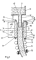
- FIG. 1 shows a feed container 41 filled with melt S, in the bottom of which 42 an opening 47 is provided, on which a dip tube 43 is arranged, which protrudes into a mold 11.
- the mold 11 has mold broad sides 14 and narrow sides, not shown here 15.
- the wide mold side 14 shown on the right in FIG. 1 has on it Inner wall is a coating 18.
- there is a mold 14 on this broad side Vibration exciter 21 on the end face 19 and a further vibration exciter 21 attached in the entrance area 17.
- the mold mouth 13 of this mold broadside 14 tapers conically and is supported with its tip 16 on an abutment 31, the has a contact surface 32.
- the mold broad side 14 shown on the left side of the mold 11 is on the Mold mouth 13 on an abutment 31.
- On the end face 19 is as Vibration exciter attached to an unbalance exciter 22.
- this wide mold side 14 has a water tank 81, which with a Bellows 46 is connected to the bottom 42 of the inflow container 41.
- a shell box K which surrounds the melt S, is formed over guide rollers 71, which are connected downstream of the mold 11, and over Driving rollers 72 is conveyed out of the mold.
- the feed container 41 is designed as a vacuum device 61 which has a vacuum device 62.
- An opening 47 is provided in the bottom 42 of the feed container 41, the cross-sectional area A Z of which is smaller than the cross-sectional area A K of the mold. So there was no immersion nozzle.
- the mold 11 is arranged below the opening 47 of the feed container 41 which the mold broad sides 14 are shown. Support the mold broad sides 14 abut on abutments 31 provided with a contact surface 32. Of the two The mold broad sides 14 shown have only the right one coating 18.
- Both broad mold sides 14 are provided with water boxes 81, one of which gas-tight connection 45 is attached, which to the bottom 42 of the feed container 41 communicates.
- the gas-tight connection 45 is connected via a connection 51 connected to a gas supply 52. With this gas supply 52 can be in the room between the bottom 42, the gas-tight connections 45 and the surface of the in the mold 11 located melt S negative pressure or positive pressure are generated. The melt leaving the feed container 41 through the opening 47 falls freely the mold 11.
- the shell box K produced in the mold 11 is above the mold Guide rollers 71 guided and drive rollers 72 from the mold 11 conveyed out.
- the wide mold sides 14 are tapered at the mold mouth 13 to a cone tip 16 with the width b and have a length L K.
- a piezo crystal 24 is fastened on the left end face 19 and a capacitor plate 23 is fastened on the right hand side.
Landscapes
- Engineering & Computer Science (AREA)
- Mechanical Engineering (AREA)
- Continuous Casting (AREA)
- Processing Of Solid Wastes (AREA)
- Metal Extraction Processes (AREA)
Description
- Figur 1
- schematisch einen Schnitt durch die Kokille
- Figur 2
- eine Stranggießeinrichtung bestehend aus Zuführgefäß und Kokille sowie Führungsrollen.
Auf der linken Seite ist auf der kompletten Stirnfläche 19 ein Piezo-Kristall 24 und auf der rechten Seite eine Kondensatorplatte 23 befestigt.
Claims (16)
- Verfahren zum Abziehen eines in einer Stranggießanlage erzeugten Metallstranges mit einer stationären Kokille (11), insbesondere zum Gießen von Stahl, in der der Metallstrang einen das flüssige Metall umhüllenden Schalenkasten (K) erhält, wobei der Kokille mit Führungsrollen (71) bestückte Gerüste nachgeschaltet sind, gekennzeichnet durch folgende Schritte:wobei die Länge (LW) der Schwingung kleiner ist als die Länge (LK) der Kokillenwand in Strangförderrichtung und wobei gleichzeitig der Strang von den der Kokille nachgeordneten Antriebsrollen (72) abgezogen wird, wobei der Fördervorgang unabhängig von der aktuellen Kokillenschwingfrequenz ist.die fußseitig auf einem Widerlager (31) abgestellten Wände (14,15) der Kokille (11) werden kopfseitig von der Stirnfläche beginnend in ihrer vollen Länge derart zu einer Schwingung > 400 Hz angeregt, dass ausschließlich ein Negativstrip zum Schalenkasten (K) des Stranges vorliegt,
- Verfahren nach Anspruch 1,
dadurch gekennzeichnet, dass die Schwingungen über den gesamten Umfang der Stirnfläche der Kokillen in die Kokillenwände indiziert werden. - Verfahren nach Anspruch 2,
dadurch gekennzeichnet, dass eine solche Amplitude der Schwingung gewählt wird, die unter Berücksichtigung der Rauhigkeit der Innenflächen der Kokillenwände ein Kleben des Schalenkastens an ihnen verhindert. - Vorrichtung zur Schwingungsanregung einer stationären Kokille zum Stranggießen von Metallen, insbesondere Stahl, wobei der Kokille mit Führungsrollen bestückte Gerüste nachgeordnet sind, zur Durchführung des Verfahrens nach Anspruch 1,
dadurch gekennzeichnet, dass Schwingungserreger (21) vorgesehen sind, die mindestens im Kopfbereich (12) der Kokille (11) angeordnet sind,
dass die Kokillenwände (15, 16) eine Länge (LK) besitzen, die größer ist als die Länge (LW) der Spannungswelle der Schwingung,
dass die Mündung (13) der Kokille (11) auf einem Widerlager (31) aufliegt und dass der Kokille Antriebsrollen (72) zum Abziehen des Stranges nachgeschaltet sind. - Vorrichtung nach Anspruch 4,
dadurch gekennzeichnet, daß die Schwingungserreger (21) über die gesamte Umfangslänge der Stirnfläche (19) der Kokille (11) mit dieser gekoppelt sind. - Vorrichtung nach Anspruch 5,
dadurch gekennzeichnet, daß die Schwingungserreger (21) mechanisch angetrieben sind, wobei insbesondere Unwuchterreger (22) eingesetzt werden. - Vorrichtung nach Anspruch 5,
dadurch gekennzeichnet, daß die Schwingungserreger (21) elektrisch angetrieben sind, wobei insbesondere Kondensatorplatten eingesetzt werden. - Vorrichtung nach Anspruch 5,
dadurch gekennzeichnet, daß die Schwingungserreger (21) Piezo-Kristalle (24) sind. - Vorrichtung nach Anspruch 4,
dadurch gekennzeichnet, daß die Kokillenwände (14, 15) im Mündungsbereich (13) in Richtung Widerlager (31) sich konisch verjüngen, und
daß die Konusspitze (16) eine Breite (b) von b < 1 mm aufweist. - Vorrichtung nach Anspruch 4,
dadurch gekennzeichnet, daß die zum Formhohlraum weisenden Innenflächen der Kokillenwände (14, 15) eine thermisch sowie chemisch resistente Beschichtung (18) aufweisen, z.B. aus keramischen Werkstoffen bestehen. - Vorrichtung nach Anspruch 10,
dadurch gekennzeichnet, daß die Beschichtung (18) eine Rauhigkeit besitzt, die kleiner ist als die Amplitude der in die Kokillenwände (15, 16) indizierten Spannungswellen. - Vorrichtung nach Anspruch 4,
dadurch gekennzeichnet, daß der Kokille (11) ein Zuführbehälter (41) für flüssiges Metall vorgeschaltet ist, an dessen Boden (41) ein Tauchgießrohr (43) vorgesehen ist, welches in den Freiraum der Kokille (11) ragt, und
daß zwischen dem Zuführbehälter (41) und dem Kokilleneingang (17) eine Abschirmung (44) vorgesehen ist, an der ein Anschluß (51) angebracht ist, der mit einer Gasversorgung (52), inbesondere für Inertgas, verbunden ist. - Vorrichtung nach Anspruch 12,
dadurch gekennzeichnet, daß die Abschirmung (44) als Balg (46) ausgestaltet ist. - Vorrichtung nach Anspruch 4,
dadurch gekennzeichnet, daß der Kokille (11) ein Zuführbehälter (41) für flüssiges Metall vorgeschaltet ist, dessen Boden (42) eine Öffnung (47) aufweist, deren Austrittsfläche (AZ) 10 bis 14 % kleiner ist als die Querschnittsfläche (AK) der Kokille,
daß außerhalb der Öffnung (47) an der Außenseite des Bodens (42) des Zuführbehälters (41) eine Hülse (48) befestigt ist, die sich mündungsseitig gasdicht an die Stim der Kokille (11) außerhalb der Schwingungserreger (21) anlehnt. - Vorrichtung nach Anspruch 12 oder 14,
dadurch gekennzeichnet, daß der Zuführbehälter (41) an eine Unterdruckeinrichtung (61) angeschlossen ist, mit der die Höhe des Gießspiegels der in die Kokille (11) einfüllbaren Schmelze steuerbar ist. - Vorrichtung nach Anspruch 14,
dadurch gekennzeichnet, daß an die Hülse (48) eine Überdruckvorrichtung (62) angeschlossen ist, mit der die Höhe des Gießspiegels der in die Kokille (11) einfüllbaren Schmelze steuerbar ist.
Applications Claiming Priority (3)
| Application Number | Priority Date | Filing Date | Title |
|---|---|---|---|
| DE19823361 | 1998-05-15 | ||
| DE19823361A DE19823361A1 (de) | 1998-05-15 | 1998-05-15 | Verfahren und Vorrichtung zum Abziehen eines Metallstranges |
| PCT/DE1999/001273 WO1999059749A1 (de) | 1998-05-15 | 1999-04-26 | Verfahren und vorrichtung zum abziehen eines metallstranges |
Publications (2)
| Publication Number | Publication Date |
|---|---|
| EP1077781A1 EP1077781A1 (de) | 2001-02-28 |
| EP1077781B1 true EP1077781B1 (de) | 2002-09-25 |
Family
ID=7868886
Family Applications (1)
| Application Number | Title | Priority Date | Filing Date |
|---|---|---|---|
| EP99929058A Expired - Lifetime EP1077781B1 (de) | 1998-05-15 | 1999-04-26 | Verfahren und vorrichtung zum abziehen eines metallstranges |
Country Status (6)
| Country | Link |
|---|---|
| EP (1) | EP1077781B1 (de) |
| AT (1) | ATE224781T1 (de) |
| AU (1) | AU4601299A (de) |
| DE (2) | DE19823361A1 (de) |
| ES (1) | ES2181450T3 (de) |
| WO (1) | WO1999059749A1 (de) |
Families Citing this family (1)
| Publication number | Priority date | Publication date | Assignee | Title |
|---|---|---|---|---|
| DE102011083016A1 (de) * | 2011-09-20 | 2013-03-21 | Sms Siemag Ag | Vorrichtung zum Stranggießen und Verwendung von piezoelektrischen Aktuatoren |
Family Cites Families (14)
| Publication number | Priority date | Publication date | Assignee | Title |
|---|---|---|---|---|
| FR873400A (fr) * | 1941-05-15 | 1942-07-07 | Usines Ernest Tordoir | Dispositif pour la coulée en continu de pièces métalliques |
| DE1120641B (de) * | 1954-05-25 | 1961-12-28 | British Iron Steel Research | Verfahren und Vorrichtung zum Giessen von Metall |
| DE1865985U (de) * | 1961-01-16 | 1963-01-24 | Hoerder Huettenunion Ag | Stranggusskokille. |
| CH626282A5 (en) * | 1976-12-29 | 1981-11-13 | Langenecker Bertwin | Method and apparatus for the treatment of metal and metal-alloy melts by means of macrosonic sound |
| JPS60203341A (ja) * | 1984-03-26 | 1985-10-14 | Kobe Steel Ltd | 鋼の無振動連続鋳造法 |
| AT379335B (de) * | 1984-05-10 | 1985-12-27 | Voest Alpine Ag | Einrichtung an einer stranggiessanlage mit einer an einem ortsfesten stuetzgeruest aufgehaengten oder abgestuetzten oszillierenden stranggiesskokille |
| FR2570626B1 (fr) * | 1984-09-26 | 1987-05-07 | Siderurgie Fse Inst Rech | Procede pour mettre en vibration une lingotiere de coulee continue afin de reduire le coefficient de frottement dans cette lingotiere et lingotiere pour la mise en oeuvre de ce procede |
| DE3543790A1 (de) * | 1985-12-09 | 1987-06-11 | Mannesmann Ag | Oszillationsvorrichtung |
| ES2032609T3 (es) * | 1988-01-28 | 1993-02-16 | Clecim | Procedimiento y dispositivo para la oscilacion de una lingotera de colada continua de acero. |
| FR2648063B1 (fr) * | 1989-06-12 | 1994-03-18 | Irsid | Procede et dispositif de mise en vibration d'une lingotiere de coulee continue des metaux |
| DE4132189C1 (en) * | 1991-09-27 | 1993-02-04 | Wieland-Werke Ag, 7900 Ulm, De | Metal strip prodn. - by feeding molten metal from tundish via casting nozzle onto cooled conveyor belt |
| DE4240849A1 (de) * | 1992-12-04 | 1994-06-09 | Didier Werke Ag | Verfahren zur Bildung eines Trennspaltes, insbesondere in der Metallurgie |
| DE19512209C1 (de) * | 1995-03-21 | 1996-07-18 | Mannesmann Ag | Verfahren und Vorrichtung zum Einfüllen metallischer Schmelze in eine Kokille |
| IT1288901B1 (it) * | 1996-05-13 | 1998-09-25 | Danieli Off Mecc | Procedimento di colata continua con campo magnetico pulsante e relativo cristallizzatore per colata continua |
-
1998
- 1998-05-15 DE DE19823361A patent/DE19823361A1/de not_active Ceased
-
1999
- 1999-04-26 EP EP99929058A patent/EP1077781B1/de not_active Expired - Lifetime
- 1999-04-26 ES ES99929058T patent/ES2181450T3/es not_active Expired - Lifetime
- 1999-04-26 WO PCT/DE1999/001273 patent/WO1999059749A1/de not_active Ceased
- 1999-04-26 DE DE59902850T patent/DE59902850D1/de not_active Expired - Fee Related
- 1999-04-26 AU AU46012/99A patent/AU4601299A/en not_active Abandoned
- 1999-04-26 AT AT99929058T patent/ATE224781T1/de not_active IP Right Cessation
Also Published As
| Publication number | Publication date |
|---|---|
| ATE224781T1 (de) | 2002-10-15 |
| AU4601299A (en) | 1999-12-06 |
| DE59902850D1 (de) | 2002-10-31 |
| DE19823361A1 (de) | 1999-11-25 |
| WO1999059749A1 (de) | 1999-11-25 |
| EP1077781A1 (de) | 2001-02-28 |
| ES2181450T3 (es) | 2003-02-16 |
Similar Documents
| Publication | Publication Date | Title |
|---|---|---|
| DE69326078T2 (de) | Bandgiessverfahren | |
| EP0043987B1 (de) | Vorrichtung zum Stranggiessen von Metall in einem geschlossenen Eingiessystem | |
| JPH0470105B2 (de) | ||
| JP3085978B2 (ja) | 薄肉スラブの製造方法及び連続鋳造装置 | |
| RU96117378A (ru) | Устройство для непрерывной разливки и способ изготовления тонких плоских слитков | |
| WO1999059749A1 (de) | Verfahren und vorrichtung zum abziehen eines metallstranges | |
| DE2758350A1 (de) | Verfahren und vorrichtung zur behandlung der schmelze von metallen und metallegierungen mittels makroschalls | |
| JPS58151949A (ja) | 浸漬ノズルの詰り防止方法 | |
| DE3047652A1 (de) | Stranggiesskokille | |
| RU96117380A (ru) | Устройство для непрерывной разливки и способ изготовления прямоугольных тонких плоских слитков | |
| DE3615856A1 (de) | Horizontale stranggiesseinrichtung | |
| DE102005009326B4 (de) | Verfahren und Gießeinrichtung zur Herstellung von Mikrogussteilen | |
| EP3946777A1 (de) | Vorrichtung und verfahren zur herstellung eines metallischen bauteiles | |
| DE3332349C2 (de) | Vorrichtung und Verfahren zum Horizontalstranggießen von Metallen | |
| EP0103606B1 (de) | Verwendung eines druckflüssigkeitsfilms zur schmierung des gussstranges beim stranggiessen | |
| EP0276357B1 (de) | Verfahren zur Herstellung von Blöcken aus Metallen, insbesondere aus Stählen | |
| DE909501C (de) | Verfahren und Einrichtung zur Bildung von Metallegierungen mittels Schall oder Ultraschall | |
| CH227633A (de) | Verfahren zum Herstellen von Gusskörpern, insbesondere aus Leichtmetall und Leichtmetallegierungen. | |
| DE202005004226U1 (de) | Vakuum-Druckgießanlage | |
| DE2750861C3 (de) | Verfahren zur Herstellung von Gußblöcken und Einrichtung zu dessen Durchfährung | |
| JPS57154353A (en) | Continuous casting method for cu and cu alloy | |
| DE2024747C3 (de) | Verfahren zum halbkontinuierllchen Stranggießen, insbesondere von Stahl, und Vorrichtung zur Durchführung des Verfahrens * | |
| JPS58224045A (ja) | 溶鋼の低温連続鋳造方法 | |
| DE3050165T1 (de) | ||
| DE3100137A1 (de) | Stranggiessverfahren und stranggussform |
Legal Events
| Date | Code | Title | Description |
|---|---|---|---|
| PUAI | Public reference made under article 153(3) epc to a published international application that has entered the european phase |
Free format text: ORIGINAL CODE: 0009012 |
|
| 17P | Request for examination filed |
Effective date: 20001113 |
|
| AK | Designated contracting states |
Kind code of ref document: A1 Designated state(s): AT DE ES FR GB IT NL |
|
| 17Q | First examination report despatched |
Effective date: 20010509 |
|
| GRAG | Despatch of communication of intention to grant |
Free format text: ORIGINAL CODE: EPIDOS AGRA |
|
| GRAG | Despatch of communication of intention to grant |
Free format text: ORIGINAL CODE: EPIDOS AGRA |
|
| GRAH | Despatch of communication of intention to grant a patent |
Free format text: ORIGINAL CODE: EPIDOS IGRA |
|
| GRAH | Despatch of communication of intention to grant a patent |
Free format text: ORIGINAL CODE: EPIDOS IGRA |
|
| GRAA | (expected) grant |
Free format text: ORIGINAL CODE: 0009210 |
|
| AK | Designated contracting states |
Kind code of ref document: B1 Designated state(s): AT DE ES FR GB IT NL |
|
| REF | Corresponds to: |
Ref document number: 224781 Country of ref document: AT Date of ref document: 20021015 Kind code of ref document: T |
|
| REG | Reference to a national code |
Ref country code: GB Ref legal event code: FG4D Free format text: NOT ENGLISH |
|
| GBT | Gb: translation of ep patent filed (gb section 77(6)(a)/1977) |
Effective date: 20020925 |
|
| REF | Corresponds to: |
Ref document number: 59902850 Country of ref document: DE Date of ref document: 20021031 |
|
| ET | Fr: translation filed | ||
| REG | Reference to a national code |
Ref country code: ES Ref legal event code: FG2A Ref document number: 2181450 Country of ref document: ES Kind code of ref document: T3 |
|
| PLBE | No opposition filed within time limit |
Free format text: ORIGINAL CODE: 0009261 |
|
| STAA | Information on the status of an ep patent application or granted ep patent |
Free format text: STATUS: NO OPPOSITION FILED WITHIN TIME LIMIT |
|
| 26N | No opposition filed |
Effective date: 20030626 |
|
| REG | Reference to a national code |
Ref country code: GB Ref legal event code: 732E |
|
| NLS | Nl: assignments of ep-patents |
Owner name: OTTO ALEXANDER SCHMIDT |
|
| PGFP | Annual fee paid to national office [announced via postgrant information from national office to epo] |
Ref country code: NL Payment date: 20070413 Year of fee payment: 9 Ref country code: AT Payment date: 20070413 Year of fee payment: 9 |
|
| PGFP | Annual fee paid to national office [announced via postgrant information from national office to epo] |
Ref country code: DE Payment date: 20070423 Year of fee payment: 9 |
|
| PGFP | Annual fee paid to national office [announced via postgrant information from national office to epo] |
Ref country code: ES Payment date: 20070427 Year of fee payment: 9 |
|
| PGFP | Annual fee paid to national office [announced via postgrant information from national office to epo] |
Ref country code: IT Payment date: 20070614 Year of fee payment: 9 |
|
| PGFP | Annual fee paid to national office [announced via postgrant information from national office to epo] |
Ref country code: FR Payment date: 20070416 Year of fee payment: 9 |
|
| PGFP | Annual fee paid to national office [announced via postgrant information from national office to epo] |
Ref country code: GB Payment date: 20080829 Year of fee payment: 10 |
|
| NLV4 | Nl: lapsed or anulled due to non-payment of the annual fee |
Effective date: 20081101 |
|
| PG25 | Lapsed in a contracting state [announced via postgrant information from national office to epo] |
Ref country code: NL Free format text: LAPSE BECAUSE OF NON-PAYMENT OF DUE FEES Effective date: 20081101 Ref country code: DE Free format text: LAPSE BECAUSE OF NON-PAYMENT OF DUE FEES Effective date: 20081101 |
|
| REG | Reference to a national code |
Ref country code: FR Ref legal event code: ST Effective date: 20081231 |
|
| PG25 | Lapsed in a contracting state [announced via postgrant information from national office to epo] |
Ref country code: AT Free format text: LAPSE BECAUSE OF NON-PAYMENT OF DUE FEES Effective date: 20080426 |
|
| PG25 | Lapsed in a contracting state [announced via postgrant information from national office to epo] |
Ref country code: FR Free format text: LAPSE BECAUSE OF NON-PAYMENT OF DUE FEES Effective date: 20080430 |
|
| REG | Reference to a national code |
Ref country code: ES Ref legal event code: FD2A Effective date: 20080428 |
|
| PG25 | Lapsed in a contracting state [announced via postgrant information from national office to epo] |
Ref country code: ES Free format text: LAPSE BECAUSE OF NON-PAYMENT OF DUE FEES Effective date: 20080428 |
|
| PG25 | Lapsed in a contracting state [announced via postgrant information from national office to epo] |
Ref country code: IT Free format text: LAPSE BECAUSE OF NON-PAYMENT OF DUE FEES Effective date: 20080426 |
|
| GBPC | Gb: european patent ceased through non-payment of renewal fee |
Effective date: 20090426 |
|
| PG25 | Lapsed in a contracting state [announced via postgrant information from national office to epo] |
Ref country code: GB Free format text: LAPSE BECAUSE OF NON-PAYMENT OF DUE FEES Effective date: 20090426 |