EP1077288A2 - Gleisbaufahrzeug zur Einschotterung eines Gleises - Google Patents
Gleisbaufahrzeug zur Einschotterung eines Gleises Download PDFInfo
- Publication number
- EP1077288A2 EP1077288A2 EP00890218A EP00890218A EP1077288A2 EP 1077288 A2 EP1077288 A2 EP 1077288A2 EP 00890218 A EP00890218 A EP 00890218A EP 00890218 A EP00890218 A EP 00890218A EP 1077288 A2 EP1077288 A2 EP 1077288A2
- Authority
- EP
- European Patent Office
- Prior art keywords
- ballast
- track
- construction vehicle
- deflector
- track construction
- Prior art date
- Legal status (The legal status is an assumption and is not a legal conclusion. Google has not performed a legal analysis and makes no representation as to the accuracy of the status listed.)
- Granted
Links
Images

Classifications
-
- E—FIXED CONSTRUCTIONS
- E01—CONSTRUCTION OF ROADS, RAILWAYS, OR BRIDGES
- E01B—PERMANENT WAY; PERMANENT-WAY TOOLS; MACHINES FOR MAKING RAILWAYS OF ALL KINDS
- E01B27/00—Placing, renewing, working, cleaning, or taking-up the ballast, with or without concurrent work on the track; Devices therefor; Packing sleepers
- E01B27/02—Placing the ballast; Making ballastway; Redistributing ballasting material; Machines or devices therefor; Levelling means
- E01B27/023—Spreading, levelling or redistributing ballast already placed
- E01B27/025—Spreading, levelling or redistributing ballast already placed by means of non-driven tools
-
- E—FIXED CONSTRUCTIONS
- E01—CONSTRUCTION OF ROADS, RAILWAYS, OR BRIDGES
- E01B—PERMANENT WAY; PERMANENT-WAY TOOLS; MACHINES FOR MAKING RAILWAYS OF ALL KINDS
- E01B27/00—Placing, renewing, working, cleaning, or taking-up the ballast, with or without concurrent work on the track; Devices therefor; Packing sleepers
- E01B27/02—Placing the ballast; Making ballastway; Redistributing ballasting material; Machines or devices therefor; Levelling means
- E01B27/022—Placing the ballast; Making ballastway; Redistributing ballasting material; Machines or devices therefor; Levelling means by devices moving on the track with or without spreading or levelling
-
- E—FIXED CONSTRUCTIONS
- E01—CONSTRUCTION OF ROADS, RAILWAYS, OR BRIDGES
- E01B—PERMANENT WAY; PERMANENT-WAY TOOLS; MACHINES FOR MAKING RAILWAYS OF ALL KINDS
- E01B2203/00—Devices for working the railway-superstructure
- E01B2203/06—Placing ballast
- E01B2203/067—Special methods for posing or quantifying ballast
-
- E—FIXED CONSTRUCTIONS
- E01—CONSTRUCTION OF ROADS, RAILWAYS, OR BRIDGES
- E01B—PERMANENT WAY; PERMANENT-WAY TOOLS; MACHINES FOR MAKING RAILWAYS OF ALL KINDS
- E01B2203/00—Devices for working the railway-superstructure
- E01B2203/08—Levelling ballast or ground beneath
- E01B2203/083—Ploughs
Definitions
- the invention relates to a track construction vehicle for ballasting a track, with a machine frame supported on rail bogies, the a Ballast silo is assigned with outlet openings.
- AT 389 333 B discloses a bulk goods loading wagon that can be moved on the track. This has a V-shaped deflection element on its transfer conveyor belt on that the gravel transport optionally on the transfer conveyor steers into the next loading wagon or via discharge chutes into the track. With such a construction, the ballast can be thrown off the track not possible.
- the object of the present invention is now a track construction vehicle to create the type described above, with which the problem of an occasional occurring ballast jams can be solved with structurally simple means is.
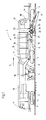
- a track construction vehicle 1 shown in FIG. 1 for ballasting a Track 2 consists essentially of a supported on rail bogies 3 Machine frame 4. According to one working direction - arrow 5 - The following work units are arranged one behind the other on the machine frame 4: A sweeper device 7 having a conveyor belt arrangement 6 Middle plow 8 and a side plow 9. All work units 7,8,9 are height-adjustable by drives 10 articulated on the machine frame 4 educated. To supply all drives as well as a travel drive 11 serves a motor 12. In the area above the middle plow 8 is located a ballast silo 13 arranged on the machine frame 4. This extends in the machine longitudinal direction from a transfer end 14 of the conveyor belt arrangement 6 to an outlet opening 15.
- a floor area of the ballast silo 13 is formed by a floor conveyor belt 16.
- driving or working cabins 17 are arranged.
- a control device 18 for Operation of the various work units provided.
- a deflector 20 attached.
- This is designed as a conveyor belt 21 and through a drive 22 from an inoperative position (shown in dash-dot lines) about a horizontal axis running in the cross machine direction 23 adjustable into a working position.
- the conveyor belt 21 is by a Drive 24 acts and runs in the cross machine direction.
- the ballast silo is already in use 13 of the track construction vehicle 1 filled. Part of the storage capacity is swept onto conveyor belt assembly 6 by sweeper 7 Gravel reserved. After reaching the job, the Sweeping device 7 and the middle plow 8 and the side plow 9 by loading the drives 10 are lowered onto the track 2. The deflector 20 is in the decommissioning position. During continuous work priority (Arrow 5) of the track construction vehicle 1, the track 2 is ballasted and profiled the bedding. Any excess ballast is removed using the Sweeping device 7 and the conveyor belt arrangement 6 in the ballast silo 13 promoted.
- ballast can be removed from the ballast silo 13 the outlet opening 15 are thrown onto the track 2. Should the ballast silo 13 be full and more ballast picked up by sweeper 7 are, by acting on the drive 22, the deflector 20 adjusted to the working position. Now the gravel can be placed next to the bed be dropped. Of course, the deflector 20 can also do this be used, the ballast silo 13 after completion of the work to empty in another place. Becomes gravel again for the bedding needed, the deflector 20 is moved back into the non-operating position.
- the deflector 20 is by means of the drive 22 in the machine longitudinal direction postponed.
- the deflector 20 has guide rollers 25, which are arranged in a longitudinal guide arranged on the machine frame 4 26 are located.
- the deflection element 20 according to FIG. 3 is driven by the drive 22 pivoted about a vertical axis 27.
- FIGS. 4 and 5 Two further exemplary embodiments, in which the deflection element 20 acts as a channel 28 is shown in FIGS. 4 and 5.
- the groove 28 is in each case stored in longitudinal guides 26 and can by a drive 22 in the machine longitudinal direction be adjusted. While the groove 28 in Fig. 4 in two parts trained to simultaneously drop the ballast on both sides of the track 2 is, the channel 28 can be adjusted according to FIG. 5 in addition.
- This Adjustment is carried out by drives 29 in the machine longitudinal direction extending axis 30. This means that the ballast can be thrown off selectively one of the two sides of track 2 possible. It would also be a combination of these two embodiments conceivable: with the help of a two-part and adjustable gutter is a drop on both, or any Feasible side of the track.
Landscapes
- Architecture (AREA)
- Civil Engineering (AREA)
- Structural Engineering (AREA)
- Engineering & Computer Science (AREA)
- Machines For Laying And Maintaining Railways (AREA)
- Road Paving Structures (AREA)
- Railway Tracks (AREA)
- Refuge Islands, Traffic Blockers, Or Guard Fence (AREA)
- Vehicle Interior And Exterior Ornaments, Soundproofing, And Insulation (AREA)
- Filling Or Emptying Of Bunkers, Hoppers, And Tanks (AREA)
- Road Signs Or Road Markings (AREA)
- Buildings Adapted To Withstand Abnormal External Influences (AREA)
- Details Of Garments (AREA)
Abstract
Description
Claims (7)
- Gleisbaufahrzeug (1) zur Einschotterung eines Gleises (2), mit einem auf Schienenfahrwerken (3) abgestützten Maschinenrahmen (4), dem ein Schottersilo (13) mit Auslaßöffnungen (15) zugeordnet ist, dadurch gekennzeichnet, daß ein Ablenkorgan (20) durch einen Antrieb (22) von einer Außerbetriebstellung in eine zur Schotteraufnahme unterhalb der Auslaßöffnung (15) befindliche Arbeitsposition verstellbar ausgebildet ist.
- Gleisbaufahrzeug nach Anspruch 1, dadurch gekennzeichnet, daß das Ablenkorgan (20) um eine horizontale, in Maschinenquerrichtung verlaufende Achse (23) verschwenkbar ausgebildet ist.
- Gleisbaufahrzeug nach Anspruch 1, dadurch gekennzeichnet, daß das Ablenkorgan (20) um eine vertikale Achse (27) verschwenkbar ausgebildet ist.
- Gleisbaufahrzeug nach Anspruch 1, dadurch gekennzeichnet, daß das Ablenkorgan (20) in Maschinenlängsrichtung verschiebbar ausgebildet ist.
- Gleisbaufahrzeug nach einem der Ansprüche 1 bis 4, dadurch gekennzeichnet, daß das Ablenkorgan (20) als Förderband (21) ausgebildet ist.
- Gleisbaufahrzeug nach einem der Ansprüche 1 bis 4, dadurch gekennzeichnet, daß das Ablenkorgan (20) als Rinne (28) ausgebildet ist.
- Gleisbaufahrzeug nach einem der Ansprüche 1 bis 6, dadurch gekennzeichnet, daß das Ablenkorgan (20) zwischen einem Flankenpflug (9) und einem Mittelpflug (8) angeordnet ist.
Priority Applications (1)
| Application Number | Priority Date | Filing Date | Title |
|---|---|---|---|
| AT00890218T ATE290126T1 (de) | 1999-08-18 | 2000-07-13 | Gleisbaufahrzeug zur einschotterung eines gleises |
Applications Claiming Priority (2)
| Application Number | Priority Date | Filing Date | Title |
|---|---|---|---|
| AT142099 | 1999-08-18 | ||
| AT142099 | 1999-08-18 |
Publications (3)
| Publication Number | Publication Date |
|---|---|
| EP1077288A2 true EP1077288A2 (de) | 2001-02-21 |
| EP1077288A3 EP1077288A3 (de) | 2001-07-04 |
| EP1077288B1 EP1077288B1 (de) | 2005-03-02 |
Family
ID=3513521
Family Applications (1)
| Application Number | Title | Priority Date | Filing Date |
|---|---|---|---|
| EP00890218A Expired - Lifetime EP1077288B1 (de) | 1999-08-18 | 2000-07-13 | Gleisbaufahrzeug zur Einschotterung eines Gleises |
Country Status (7)
| Country | Link |
|---|---|
| EP (1) | EP1077288B1 (de) |
| AT (1) | ATE290126T1 (de) |
| CZ (1) | CZ292759B6 (de) |
| DE (1) | DE50009622D1 (de) |
| DK (1) | DK1077288T3 (de) |
| ES (1) | ES2238264T3 (de) |
| PL (1) | PL199324B1 (de) |
Cited By (3)
| Publication number | Priority date | Publication date | Assignee | Title |
|---|---|---|---|---|
| AT5030U3 (de) * | 2001-11-09 | 2002-09-25 | Plasser Bahnbaumasch Franz | Gleisbaumaschine zur einbringung von schotter unterhalb eines gleises |
| AT512914A4 (de) * | 2012-06-22 | 2013-12-15 | Plasser Bahnbaumasch Franz | Schotterpflug |
| US20220349128A1 (en) * | 2019-06-26 | 2022-11-03 | System 7 Ballast Regulator Gmbh | Track ballast levelling apparatus |
Citations (2)
| Publication number | Priority date | Publication date | Assignee | Title |
|---|---|---|---|---|
| AT389333B (de) | 1986-09-08 | 1989-11-27 | Plasser Bahnbaumasch Franz | Gleisverfahrbare schuettgutverladewagen-anordnung mit regelbaren entladeschurren |
| AT404039B (de) | 1990-03-21 | 1998-07-27 | Plasser Bahnbaumasch Franz | Maschine zum verteilen und planieren des bettungsschotters |
Family Cites Families (2)
| Publication number | Priority date | Publication date | Assignee | Title |
|---|---|---|---|---|
| US2791410A (en) * | 1953-06-17 | 1957-05-07 | Material Ind S A | Apparatus for continuously cleaning railroad track ballast |
| US3371826A (en) * | 1967-01-10 | 1968-03-05 | Speno International | Ballast delivering mechanism |
-
2000
- 2000-07-13 AT AT00890218T patent/ATE290126T1/de active
- 2000-07-13 DK DK00890218T patent/DK1077288T3/da active
- 2000-07-13 ES ES00890218T patent/ES2238264T3/es not_active Expired - Lifetime
- 2000-07-13 DE DE50009622T patent/DE50009622D1/de not_active Expired - Lifetime
- 2000-07-13 EP EP00890218A patent/EP1077288B1/de not_active Expired - Lifetime
- 2000-07-19 CZ CZ20002658A patent/CZ292759B6/cs not_active IP Right Cessation
- 2000-08-01 PL PL341825A patent/PL199324B1/pl unknown
Patent Citations (2)
| Publication number | Priority date | Publication date | Assignee | Title |
|---|---|---|---|---|
| AT389333B (de) | 1986-09-08 | 1989-11-27 | Plasser Bahnbaumasch Franz | Gleisverfahrbare schuettgutverladewagen-anordnung mit regelbaren entladeschurren |
| AT404039B (de) | 1990-03-21 | 1998-07-27 | Plasser Bahnbaumasch Franz | Maschine zum verteilen und planieren des bettungsschotters |
Cited By (5)
| Publication number | Priority date | Publication date | Assignee | Title |
|---|---|---|---|---|
| AT5030U3 (de) * | 2001-11-09 | 2002-09-25 | Plasser Bahnbaumasch Franz | Gleisbaumaschine zur einbringung von schotter unterhalb eines gleises |
| EP1310597A3 (de) * | 2001-11-09 | 2004-04-14 | Franz Plasser Bahnbaumaschinen-Industriegesellschaft m.b.H. | Gleisbaumaschine zur Einbringung von Schotter unterhalb eines Gleises |
| AT512914A4 (de) * | 2012-06-22 | 2013-12-15 | Plasser Bahnbaumasch Franz | Schotterpflug |
| AT512914B1 (de) * | 2012-06-22 | 2013-12-15 | Plasser Bahnbaumasch Franz | Schotterpflug |
| US20220349128A1 (en) * | 2019-06-26 | 2022-11-03 | System 7 Ballast Regulator Gmbh | Track ballast levelling apparatus |
Also Published As
| Publication number | Publication date |
|---|---|
| EP1077288A3 (de) | 2001-07-04 |
| DE50009622D1 (de) | 2005-04-07 |
| CZ20002658A3 (cs) | 2001-04-11 |
| EP1077288B1 (de) | 2005-03-02 |
| CZ292759B6 (cs) | 2003-12-17 |
| PL341825A1 (en) | 2001-02-26 |
| PL199324B1 (pl) | 2008-09-30 |
| ES2238264T3 (es) | 2005-09-01 |
| DK1077288T3 (da) | 2005-06-13 |
| ATE290126T1 (de) | 2005-03-15 |
Similar Documents
| Publication | Publication Date | Title |
|---|---|---|
| DE4312585C2 (de) | Anlage zur kontinuierlichen Sanierung einer Schotterbettung eines Gleises | |
| EP0240648B1 (de) | Gleis-Schotterbett-Reinigungsmaschine mit Siebanlage | |
| EP0538760B1 (de) | Förder- bzw. Räumkettenanordnung für Gleisbaumaschinen | |
| CH639162A5 (de) | Selbstfahrbare gleisbett-reinigungsmaschine. | |
| AT405165B (de) | Schüttgutverladewagen | |
| DE2057197C3 (de) | Fahrbare Maschine zum Aufnehmen, Reinigen und Wiedereinbringen des Bettungsschotters von Eisenbahngleisen | |
| DD256157A5 (de) | Fahrbare anlage der schotterbeseitigung eines gleises | |
| AT3879U2 (de) | Maschine zur erneuerung eines gleises | |
| AT404039B (de) | Maschine zum verteilen und planieren des bettungsschotters | |
| EP0436757B1 (de) | Gleisstopfmaschine | |
| EP1179635B1 (de) | Maschine zum Abbau eines alten und Verlegen eines neuen Gleises | |
| CH616472A5 (de) | ||
| EP0844330A1 (de) | Schüttgutverladewagen | |
| DE4441221A1 (de) | Maschinenanlage zur Behandlung der Schotterbettung eines Gleises | |
| DE4108742C2 (de) | Gleisverfahrbare Maschine zum Verteilen und Profilieren des Bettungsschotters | |
| EP0609647A1 (de) | Maschine zum Erneuern bzw. Reinigen einer Schotterbettung | |
| DE4108743C2 (de) | Gleisverfahrbare Maschine zum Verteilen und Planieren von Bettungsschotter | |
| DE2907818A1 (de) | Fahrbare schwellenverlegeeinrichtung | |
| EP0887464A1 (de) | Maschine zum Verdichten und Profilieren der Schotterbettung eines Gleises | |
| DE2557372C2 (de) | Fahrbare Gleisbaumaschine, zum Aufnehmen, Verteilen und Wiedereinbringen von voneinander getrennten Bettungsmaterialien, insbesondere Weichenreinigungsmaschine | |
| EP0428781B1 (de) | Gleisbaumaschine zum Verteilen und Profilieren des Bettungsschotters eines Gleises | |
| AT398593B (de) | Anlage zum einschottern und unterstopfen eines gleises | |
| EP1077288B1 (de) | Gleisbaufahrzeug zur Einschotterung eines Gleises | |
| DE2927256C2 (de) | ||
| DD253267A5 (de) | Fahrbare anlage zur kontinuierlichen erneuerung der schienen und schwellen eines gleises |
Legal Events
| Date | Code | Title | Description |
|---|---|---|---|
| PUAI | Public reference made under article 153(3) epc to a published international application that has entered the european phase |
Free format text: ORIGINAL CODE: 0009012 |
|
| AK | Designated contracting states |
Kind code of ref document: A2 Designated state(s): AT BE CH CY DE DK ES FI FR GB GR IE IT LI LU MC NL PT SE |
|
| AX | Request for extension of the european patent |
Free format text: AL;LT;LV;MK;RO;SI |
|
| PUAL | Search report despatched |
Free format text: ORIGINAL CODE: 0009013 |
|
| AK | Designated contracting states |
Kind code of ref document: A3 Designated state(s): AT BE CH CY DE DK ES FI FR GB GR IE IT LI LU MC NL PT SE |
|
| AX | Request for extension of the european patent |
Free format text: AL;LT;LV;MK;RO;SI |
|
| 17P | Request for examination filed |
Effective date: 20011119 |
|
| AKX | Designation fees paid |
Free format text: AT BE CH CY DE DK ES FI FR GB GR IE IT LI LU MC NL PT SE |
|
| GRAP | Despatch of communication of intention to grant a patent |
Free format text: ORIGINAL CODE: EPIDOSNIGR1 |
|
| GRAS | Grant fee paid |
Free format text: ORIGINAL CODE: EPIDOSNIGR3 |
|
| GRAA | (expected) grant |
Free format text: ORIGINAL CODE: 0009210 |
|
| AK | Designated contracting states |
Kind code of ref document: B1 Designated state(s): AT BE CH CY DE DK ES FI FR GB GR IE IT LI LU MC NL PT SE |
|
| PG25 | Lapsed in a contracting state [announced via postgrant information from national office to epo] |
Ref country code: IE Free format text: LAPSE BECAUSE OF FAILURE TO SUBMIT A TRANSLATION OF THE DESCRIPTION OR TO PAY THE FEE WITHIN THE PRESCRIBED TIME-LIMIT Effective date: 20050302 |
|
| REG | Reference to a national code |
Ref country code: GB Ref legal event code: FG4D Free format text: NOT ENGLISH |
|
| REG | Reference to a national code |
Ref country code: CH Ref legal event code: EP |
|
| GBT | Gb: translation of ep patent filed (gb section 77(6)(a)/1977) |
Effective date: 20050302 |
|
| REG | Reference to a national code |
Ref country code: IE Ref legal event code: FG4D Free format text: GERMAN |
|
| REF | Corresponds to: |
Ref document number: 50009622 Country of ref document: DE Date of ref document: 20050407 Kind code of ref document: P |
|
| REG | Reference to a national code |
Ref country code: SE Ref legal event code: TRGR |
|
| PG25 | Lapsed in a contracting state [announced via postgrant information from national office to epo] |
Ref country code: GR Free format text: LAPSE BECAUSE OF FAILURE TO SUBMIT A TRANSLATION OF THE DESCRIPTION OR TO PAY THE FEE WITHIN THE PRESCRIBED TIME-LIMIT Effective date: 20050602 |
|
| REG | Reference to a national code |
Ref country code: DK Ref legal event code: T3 |
|
| PG25 | Lapsed in a contracting state [announced via postgrant information from national office to epo] |
Ref country code: LU Free format text: LAPSE BECAUSE OF NON-PAYMENT OF DUE FEES Effective date: 20050713 Ref country code: CY Free format text: LAPSE BECAUSE OF FAILURE TO SUBMIT A TRANSLATION OF THE DESCRIPTION OR TO PAY THE FEE WITHIN THE PRESCRIBED TIME-LIMIT Effective date: 20050713 |
|
| PG25 | Lapsed in a contracting state [announced via postgrant information from national office to epo] |
Ref country code: MC Free format text: LAPSE BECAUSE OF NON-PAYMENT OF DUE FEES Effective date: 20050731 |
|
| PG25 | Lapsed in a contracting state [announced via postgrant information from national office to epo] |
Ref country code: PT Free format text: LAPSE BECAUSE OF FAILURE TO SUBMIT A TRANSLATION OF THE DESCRIPTION OR TO PAY THE FEE WITHIN THE PRESCRIBED TIME-LIMIT Effective date: 20050817 |
|
| REG | Reference to a national code |
Ref country code: ES Ref legal event code: FG2A Ref document number: 2238264 Country of ref document: ES Kind code of ref document: T3 |
|
| REG | Reference to a national code |
Ref country code: IE Ref legal event code: FD4D |
|
| PLBE | No opposition filed within time limit |
Free format text: ORIGINAL CODE: 0009261 |
|
| STAA | Information on the status of an ep patent application or granted ep patent |
Free format text: STATUS: NO OPPOSITION FILED WITHIN TIME LIMIT |
|
| ET | Fr: translation filed | ||
| 26N | No opposition filed |
Effective date: 20051205 |
|
| PG25 | Lapsed in a contracting state [announced via postgrant information from national office to epo] |
Ref country code: IT Free format text: LAPSE BECAUSE OF NON-PAYMENT OF DUE FEES Effective date: 20070713 |
|
| REG | Reference to a national code |
Ref country code: DE Ref legal event code: R082 Ref document number: 50009622 Country of ref document: DE Representative=s name: RAU, SCHNECK & HUEBNER PATENTANWAELTE RECHTSAN, DE |
|
| REG | Reference to a national code |
Ref country code: DE Ref legal event code: R082 Ref document number: 50009622 Country of ref document: DE Representative=s name: RAU, SCHNECK & HUEBNER PATENTANWAELTE RECHTSAN, DE Effective date: 20141001 Ref country code: DE Ref legal event code: R081 Ref document number: 50009622 Country of ref document: DE Owner name: PLASSER & THEURER, EXPORT VON BAHNBAUMASCHINEN, AT Free format text: FORMER OWNER: FRANZ PLASSER BAHNBAUMASCHINEN-INDUSTRIEGESELLSCHAFT M.B.H., WIEN, AT Effective date: 20141001 |
|
| REG | Reference to a national code |
Ref country code: FR Ref legal event code: PLFP Year of fee payment: 16 |
|
| REG | Reference to a national code |
Ref country code: FR Ref legal event code: PLFP Year of fee payment: 17 |
|
| REG | Reference to a national code |
Ref country code: FR Ref legal event code: PLFP Year of fee payment: 18 |
|
| PGFP | Annual fee paid to national office [announced via postgrant information from national office to epo] |
Ref country code: NL Payment date: 20170711 Year of fee payment: 18 |
|
| PGFP | Annual fee paid to national office [announced via postgrant information from national office to epo] |
Ref country code: FI Payment date: 20170706 Year of fee payment: 18 Ref country code: ES Payment date: 20170901 Year of fee payment: 18 Ref country code: IT Payment date: 20170721 Year of fee payment: 18 |
|
| PGFP | Annual fee paid to national office [announced via postgrant information from national office to epo] |
Ref country code: SE Payment date: 20170711 Year of fee payment: 18 Ref country code: DK Payment date: 20170711 Year of fee payment: 18 Ref country code: BE Payment date: 20170711 Year of fee payment: 18 |
|
| REG | Reference to a national code |
Ref country code: FR Ref legal event code: PLFP Year of fee payment: 19 |
|
| PGFP | Annual fee paid to national office [announced via postgrant information from national office to epo] |
Ref country code: FR Payment date: 20180709 Year of fee payment: 19 Ref country code: DE Payment date: 20180924 Year of fee payment: 19 Ref country code: GB Payment date: 20180618 Year of fee payment: 19 |
|
| PGFP | Annual fee paid to national office [announced via postgrant information from national office to epo] |
Ref country code: CH Payment date: 20180710 Year of fee payment: 19 Ref country code: AT Payment date: 20180611 Year of fee payment: 19 |
|
| REG | Reference to a national code |
Ref country code: DK Ref legal event code: EBP Effective date: 20180731 |
|
| REG | Reference to a national code |
Ref country code: NL Ref legal event code: MM Effective date: 20180801 |
|
| REG | Reference to a national code |
Ref country code: BE Ref legal event code: MM Effective date: 20180731 |
|
| PG25 | Lapsed in a contracting state [announced via postgrant information from national office to epo] |
Ref country code: FI Free format text: LAPSE BECAUSE OF NON-PAYMENT OF DUE FEES Effective date: 20180713 |
|
| PG25 | Lapsed in a contracting state [announced via postgrant information from national office to epo] |
Ref country code: BE Free format text: LAPSE BECAUSE OF NON-PAYMENT OF DUE FEES Effective date: 20180731 Ref country code: SE Free format text: LAPSE BECAUSE OF NON-PAYMENT OF DUE FEES Effective date: 20180714 Ref country code: NL Free format text: LAPSE BECAUSE OF NON-PAYMENT OF DUE FEES Effective date: 20180801 |
|
| PG25 | Lapsed in a contracting state [announced via postgrant information from national office to epo] |
Ref country code: DK Free format text: LAPSE BECAUSE OF NON-PAYMENT OF DUE FEES Effective date: 20180731 Ref country code: IT Free format text: LAPSE BECAUSE OF NON-PAYMENT OF DUE FEES Effective date: 20180713 |
|
| REG | Reference to a national code |
Ref country code: ES Ref legal event code: FD2A Effective date: 20190917 |
|
| PG25 | Lapsed in a contracting state [announced via postgrant information from national office to epo] |
Ref country code: ES Free format text: LAPSE BECAUSE OF NON-PAYMENT OF DUE FEES Effective date: 20180714 |
|
| REG | Reference to a national code |
Ref country code: DE Ref legal event code: R119 Ref document number: 50009622 Country of ref document: DE |
|
| REG | Reference to a national code |
Ref country code: CH Ref legal event code: PL |
|
| REG | Reference to a national code |
Ref country code: AT Ref legal event code: MM01 Ref document number: 290126 Country of ref document: AT Kind code of ref document: T Effective date: 20190713 |
|
| GBPC | Gb: european patent ceased through non-payment of renewal fee |
Effective date: 20190713 |
|
| PG25 | Lapsed in a contracting state [announced via postgrant information from national office to epo] |
Ref country code: DE Free format text: LAPSE BECAUSE OF NON-PAYMENT OF DUE FEES Effective date: 20200201 Ref country code: GB Free format text: LAPSE BECAUSE OF NON-PAYMENT OF DUE FEES Effective date: 20190713 Ref country code: AT Free format text: LAPSE BECAUSE OF NON-PAYMENT OF DUE FEES Effective date: 20190713 |
|
| PG25 | Lapsed in a contracting state [announced via postgrant information from national office to epo] |
Ref country code: LI Free format text: LAPSE BECAUSE OF NON-PAYMENT OF DUE FEES Effective date: 20190731 Ref country code: CH Free format text: LAPSE BECAUSE OF NON-PAYMENT OF DUE FEES Effective date: 20190731 |
|
| PG25 | Lapsed in a contracting state [announced via postgrant information from national office to epo] |
Ref country code: FR Free format text: LAPSE BECAUSE OF NON-PAYMENT OF DUE FEES Effective date: 20190731 |