EP1076236B1 - Instrument de mesure optique - Google Patents
Instrument de mesure optique Download PDFInfo
- Publication number
- EP1076236B1 EP1076236B1 EP19990917155 EP99917155A EP1076236B1 EP 1076236 B1 EP1076236 B1 EP 1076236B1 EP 19990917155 EP19990917155 EP 19990917155 EP 99917155 A EP99917155 A EP 99917155A EP 1076236 B1 EP1076236 B1 EP 1076236B1
- Authority
- EP
- European Patent Office
- Prior art keywords
- measurement
- displaying
- window
- display
- light
- Prior art date
- Legal status (The legal status is an assumption and is not a legal conclusion. Google has not performed a legal analysis and makes no representation as to the accuracy of the status listed.)
- Expired - Lifetime
Links
Images


Classifications
-
- G—PHYSICS
- G01—MEASURING; TESTING
- G01N—INVESTIGATING OR ANALYSING MATERIALS BY DETERMINING THEIR CHEMICAL OR PHYSICAL PROPERTIES
- G01N21/00—Investigating or analysing materials by the use of optical means, i.e. using sub-millimetre waves, infrared, visible or ultraviolet light
- G01N21/17—Systems in which incident light is modified in accordance with the properties of the material investigated
- G01N21/47—Scattering, i.e. diffuse reflection
- G01N21/49—Scattering, i.e. diffuse reflection within a body or fluid
-
- A—HUMAN NECESSITIES
- A61—MEDICAL OR VETERINARY SCIENCE; HYGIENE
- A61B—DIAGNOSIS; SURGERY; IDENTIFICATION
- A61B5/00—Measuring for diagnostic purposes; Identification of persons
- A61B5/145—Measuring characteristics of blood in vivo, e.g. gas concentration, pH value; Measuring characteristics of body fluids or tissues, e.g. interstitial fluid, cerebral tissue
- A61B5/1455—Measuring characteristics of blood in vivo, e.g. gas concentration, pH value; Measuring characteristics of body fluids or tissues, e.g. interstitial fluid, cerebral tissue using optical sensors, e.g. spectral photometrical oximeters
- A61B5/14551—Measuring characteristics of blood in vivo, e.g. gas concentration, pH value; Measuring characteristics of body fluids or tissues, e.g. interstitial fluid, cerebral tissue using optical sensors, e.g. spectral photometrical oximeters for measuring blood gases
- A61B5/14553—Measuring characteristics of blood in vivo, e.g. gas concentration, pH value; Measuring characteristics of body fluids or tissues, e.g. interstitial fluid, cerebral tissue using optical sensors, e.g. spectral photometrical oximeters for measuring blood gases specially adapted for cerebral tissue
-
- A—HUMAN NECESSITIES
- A61—MEDICAL OR VETERINARY SCIENCE; HYGIENE
- A61B—DIAGNOSIS; SURGERY; IDENTIFICATION
- A61B5/00—Measuring for diagnostic purposes; Identification of persons
- A61B5/74—Details of notification to user or communication with user or patient ; user input means
- A61B5/742—Details of notification to user or communication with user or patient ; user input means using visual displays
- A61B5/7435—Displaying user selection data, e.g. icons in a graphical user interface
-
- A—HUMAN NECESSITIES
- A61—MEDICAL OR VETERINARY SCIENCE; HYGIENE
- A61B—DIAGNOSIS; SURGERY; IDENTIFICATION
- A61B5/00—Measuring for diagnostic purposes; Identification of persons
- A61B5/0033—Features or image-related aspects of imaging apparatus classified in A61B5/00, e.g. for MRI, optical tomography or impedance tomography apparatus; arrangements of imaging apparatus in a room
- A61B5/004—Features or image-related aspects of imaging apparatus classified in A61B5/00, e.g. for MRI, optical tomography or impedance tomography apparatus; arrangements of imaging apparatus in a room adapted for image acquisition of a particular organ or body part
- A61B5/0042—Features or image-related aspects of imaging apparatus classified in A61B5/00, e.g. for MRI, optical tomography or impedance tomography apparatus; arrangements of imaging apparatus in a room adapted for image acquisition of a particular organ or body part for the brain
Definitions
- the present invention relates to an optical measurement system, and particularly, to an optical measurement system which is suitable for optically measuring the inside of a biological body and imaging the inside of the biological body based on information signals obtained by the measurement.
- a technology of easily measuring the inside of a biological body without affecting any ill effect on the biological body is desired in the field of clinical treatment. Measurement using light is very effective for this desire.
- the first reason is that oxygen metabolism inside the biological body corresponds to a concentration of specific pigments (hemoglobin, cytochrome a a3, myoglobin and so on), that is, light absorbents in the biological body, and the concentration of the pigments can be obtained from an amount of absorbed light (in a wavelength band from visible light to near-infrared light).
- the second reason is that light can be easily handled using an optical fiber.
- WO9810698 discloses a continuous wave spectrophotometer including several sources and detectors attached to an optical module mounted on the head of the examined subject.
- the optical module includes twelve light sources and four light detectors mounted on a plastic material.
- the light sources and the light detectors are located on a geometrical pattern that provides sixteen source-detector combinations having a selected source-detector separation.
- An object of the present invention is to provide an optical measurement system which is suitable for optically measuring a body to be inspected and easily obtaining an image of a desired item based on information obtained by the measurement.
- measuring positions and a layout of optical fibers specific in the multi-channel optical measurement system are presented to an operator using a display portion. Further, by adding a function of changing the displayed layout corresponding to a measuring signal, it becomes easy to understand the status of the channels. Furthermore, a limited number of windows for inputting measurement conditions are displayed on the display portion, and measurement conditions in the next level hierarchy are displayed after completion of the inputting.
- the object is met by the optical measurement system of claim 1.
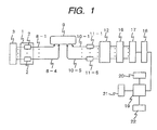
- FIG. 1 is a block diagram showing the construction of the main portion of an embodiment of an optical measurement system to which the present invention is applied.
- the present embodiment is that light is irradiated, for example, on the skin of a head and then light penetrating into and scattered by the body is detected from the skin to image the inside of the cerebrum.
- number of measurement channels that is, number of measurement positions is 12.
- the object to be measured is not limited to a head, and the present invention can be applied to the other portions and to an object other than a biological body.
- a light source portion 1 is composed of four light modules 2.
- Each of the light modules is composed of a plurality of semiconductor lasers each emitting light having a different wavelength within a wavelength band from visual to infrared, for example, two semiconductor lasers each emitting light having either of 780 nm or 830 nm wavelength. These values of two wavelengths are not limited to 780 nm and 830 nm, and number of wavelengths is not limited to two.
- light emitting diodes may be used instead of the semiconductor lasers.
- the light from all of the eight semiconductor lasers contained in the light source portion 1 is modulated by a oscillating portion 3 composed of eight oscillators having different oscillation frequency, respectively.
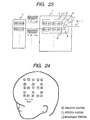
- FIG. 23 shows the construction inside the light module 2 by taking the light module 2(1) as an example.
- Semiconductor lasers 3(1-a), 3(1-b) and drive circuits 4(1-a), 4(1-b) for the semiconductor lasers are contained in the light module 2(1).
- the numeral indicates the number of the light module containing the semiconductor laser or the semiconductor laser drive circuit
- the characters a and b indicate for wavelengths 780 nm and 830 nm, respectively.
- the semiconductor laser drive circuits 4(1-a), 4(1-b) apply direct current bias current to the semiconductor lasers 3(1-a), 3(1-b), and also apply voltages having frequencies f(1-a), f(1-b) different from each other to the oscillators 3, respectively, to modulate light beams emitted from the semiconductor lasers 3(1-a), 3(1-b).
- the modulation in the present embodiment is analogue modulation using sinusoidal waves, but of course, digital modulation using rectangular waves having time intervals different from each other may be used.
- Each of the light beams modulated as described above is introduced into each of optical fibers 6 through each of condenser lenses 5 for each of the semiconductor lasers.
- Each of the light beams of the two wavelengths introduced into each of the optical fibers is introduced into an optical fiber, for example, an irradiation optical fiber 8-1 by an optical fiber coupler 7.
- the two-wavelength light beams from the light modules are introduced into the irradiation optical fibers 8-1 to 8-4, respectively, and irradiated onto four different irradiation positions on the surface of a body 9 to be inspected out of the other ends of the irradiation optical fibers.
- Light reflected from the body to be inspected is detected by detecting optical fibers 10-1 to 10-5 arranged at five detecting positions.
- each of the optical fibers is softly in contact with the surface of the body 9 to be inspected, that is, the optical fiber is attached to the body 9 to be inspected using, for example, a probe described in Japanese Patent Application Laid-Open No.9-149903.
- FIG. 24 is a view showing an example of a geographical arrangement of the irradiation positions 1 to 4 and the detecting positions 1 to 5 on a surface of the body 9 to be inspected.
- the irradiation position and the detecting position are alternatively arranged on a square lattice. Assuming that the middle position between the irradiation position and the detecting position adjacent to each other is a measured position, number of measured positions, that is, number of measurement channels is 12 because there are 12 combinations of the irradiation position and the detecting position adjacent to each other.
- the present embodiment shows the case where the number of measurement channels is 12 in order to simplify the explanation, the measurement area can be easily expanded by further increasing numbers of the light irradiation positions and the light detecting positions arranged in a lattice to further increase number of measurement channels.
- the reflected light detected by each of the detecting optical fibers 10-1 to 10-5 is detected on the detecting position basis, that is, detected independently in the detecting optical fiber corresponding to each of the detecting positions using the five light detectors, for example, using the photo-diodes 11-1 to 11-5.
- the photo-diode is preferably an avalanche photo-diode which can realize high sensitive light measurement. Further, a photo-multiplier tube may be used as the light detector.
- a modulated signal corresponding to both of the irradiation position and the wavelength is selectively detected by the lock-in amplifier module 12 composed of a plurality of circuits for selectively detecting a modulated signal, for example, a plurality of lock-in amplifiers.
- the lock-in amplifiers are shown as the modulated signal detecting circuits coping with the case of analogue modulation, digital filters or digital processors for detecting the modulated signals are used in a case of using digital modulation.
- FIG. 25 is a block diagram showing the construction of lock-in amplifier module of FIG. 1. Initially, explanation will be made on modulated signal separation of the detected signal detected by the photo-diode 11-1 at the position 1 in FIG. 24.
- the light irradiated at the "light irradiation position 1", at the “light irradiation position 2", at the “light irradiation position 3" and at the "light irradiation position 4" adjacent to the detecting position 1 can be detected, and accordingly the "measured position 4", the “measured position 6", the “measured position 7" and the “measured position 9" in FIG. 24 are positions to be measured.
- the detected signal detected by the photo-diode 11-1 at the "position 1" includes eight signal components having the modulation frequencies of f(1-a), f(1-b), f(2-a), f(2-b), f(3-a), f(3-b), f(4-a) and f(4-b) corresponding to the two-wavelength light each irradiated onto the "irradiation position 1", the "irradiation position 2", the "irradiation position 3" and the "irradiation position 4".
- the light signals containing the eight signal components are introduced into the eight lock-in amplifiers 13-1 to 13-8 through the 8 amplifiers 14-1 to 14-8.
- Modulation frequency signals of f(1-a), f(1-b), f(2-a), f(2-b), f(3-a), f(3-b), f(4-a) and f(4-b) are given to the 8 lock-in amplifiers 13-1 to 13-8 as reference signals, respectively.
- the light signal components of 780 nm and 830 nm wavelengths irradiated onto the "irradiation position 1" are selectively separated by the lock-in amplifiers 13-1 and 13-2; the light signal components of 780 nm and 830 nm wavelengths irradiated onto the "irradiation position 2" are selectively separated by the lock-in amplifiers 13-3 and 13-4; the light signal components of 780 nm and 830 nm wavelengths irradiated onto the "irradiation position 3" are selectively separated by the lock-in amplifiers 13-5 and 13-6; and the light signal components of 780 nm and 830 nm wavelengths irradiated onto the "irradiation position 4" are selectively separated by the lock-in amplifiers 13-7 and 13-8.
- the desired light signal components are similarly selectively separated to be lock-in detected.
- the light signal detected by the photo-diode 11-2 at the "detecting position 2" is introduced into the four lock-in amplifiers 13-9 to 13-12 through the four amplifiers 14-9 to 14-12, and the light components of 780 nm and 830 nm wavelengths irradiated at the "irradiation position 1" and the light components of 780 nm and 830 nm wavelengths irradiated at the "irradiation position 2" each are selectively separated to be lock-in detected;
- the light signal detected by the photo-diode 11-3 at the "detecting position 3" is introduced into the four lock-in amplifiers 13-13 to 13-16 through the four amplifiers 14-13 to 14-16, and the light components of 780 nm and 830 nm wavelengths irradiated at the "irradiation position 1" and the light components of 780 nm and 830 nm wavelengths irradiated at the "irradiation position 3" each are selectively separated to be lock-in detected; the light
- the positions to be measured are the “measured position 1" and the measured position 3", the measured position 2" and the “measured position 5", the measured position 10", and the “measured position 8" and the “measured position 11".
- each of the analogue signals output from the lock-in amplifiers 13-1 to 13-24 (channel 1 to 24) is accumulated for a preset time by a sample hold circuit of the channel corresponding to the sample hold circuit module 16.
- the switch (multiplexer) 17 is sequentially switched to convert the signal accumulated in each of the sample hold circuits to a digital signal, for example, by a 12-bit analogue/digital converter (A/D converter) 18, and the converted signals in all of the channels are stored in a memory unit outside a computer 19.
- the converted signals may be stored in a memory unit inside the computer 19.
- the channel number corresponds to the address of the memory unit with a one to one relation
- the switch 17 is repetitively switched at high speed.
- the analogue signal of each channel is converted into a digital signal using the analogue/digital converter 18 every switching to be accumulated in the memory unit 20, and the digital signals acquired a preset number of times are averaged on the channel basis to be stored in the memory unit 20.
- This method can reduce noise of high frequency components.
- the computer 19 may be a personal computer.
- An operating portion 22 is connected to the computer 19, and the operating portion includes a keyboard, a mouse and so on for inputting and outputting various kinds of information and for adding and deleting data.
- FIG. 26 is a graph showing time variation of a measured signal 30 at a detecting position and of a predicted no-load signal 31 obtained from the measured signal. The graph is displayed on the display portion 21, and the abscissa indicates measurement time and the ordinate indicates an amount of relative change in hemoglobin concentration, that is, the amount corresponding to change in hemoglobin concentration at a specific position in a cerebrum caused by motion of a specific position of a body (for example, motion of a part of the body such as a finger or the like).
- the predicted no-load signal 31 is obtained from the measured signal 30 by fitting an arbitrary function to the measured signal 31 in the time before loading T1 and the time after applying load T3 except the signals in the time applying load (loading time) Tt and the time until the signal returns the original value (relaxation time) T2 through the least-squares method.
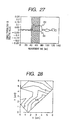
- FIG. 27 shows an example of time variations of an amount of relative change in concentrations of oxygenated hemoglobin and an amount of relative change in concentrations of deoxygenated hemoglobin at a measurement position.
- the graph is displayed on the display portion 21.
- the abscissa indicates measurement time and the ordinate indicates relative amounts of change in the concentrations.
- the time illustrated by the hatched area is a load applying time (a period of moving a finger of right hand).
- the relative amounts of changes in oxygenated hemoglobin and in deoxygenated hemoglobin (H b O 2 , H b ) associated with load application is calculated based on the non-load signal 31 and the predicted non-load signal 32 through a predetermined calculation processing.
- FIG. 28 and FIG. 29 shows a contour image (a topography image) produced from the time variation of the relative amount of change in a concentration of oxygenated hemoglobin at each measurement position displayed in the display portion 21 when motion of left-hand or right-hand fingers of a person to be inspected is used as load, respectively.
- the topography image is formed by calculating an integrated value with time (an averaged value with time may be acceptable) of the signal of relative amount of change 32 in the load applying time (the hatched period in FIG. 27) by the processing portion 19, and linearly interpolating between the measured positions in the X-axis direction and the Y-axis direction.
- a monochrome gray-scale image or a color identifying image may be acceptable instead of the contour image shown in FIG. 28 and FIG. 29. It can be understood from FIG. 28 and FIG. 29 that the oxygenated hemoglobin concentration is clearly increased at a specific position when right-hand finger is moved.
- FIG. 28 and FIG. 29 are formed using the time-integrated values of the relative amount of change in concentration during the load apply time period, a similar topography image can be formed using relative amounts of change in oxygenated hemoglobin concentration at the measured positions every measuring time performed at a time.
- a similar topography image can be formed using relative amounts of change in oxygenated hemoglobin concentration at the measured positions every measuring time performed at a time.
- a topography image for each position can be also formed from the correlation functions. Since the correlation function at each position is a function defined by shifting time by ⁇ , a state of propagation of change in a dynamic blood state can be visualized by forming photography images from the values of the correlation functions shifting by the same time of ⁇ and displaying the photography images in order of ⁇ or as a moving picture.
- the relative amount of change in oxygenated hemoglobin concentration As the typical example, the relative amount of change in deoxygenated hemoglobin concentration and the relative amount of change in the total hemoglobin concentration calculated as the sum of the relative amounts of change in oxygenated and deoxygenated hemoglobin concentrations can be similarly formed in the topography images.
- FIG. 30 shows an example of a display superposing a topography image 34 formed through the method described above on a cerebrum surface image 35 of a person to be inspected. Since the topography image 34 is change in a dynamic blood state of a cerebrum changing in association with change in a biological function, it is preferable that the topography image is displayed by superposing on the cerebrum surface image.
- the cerebrum surface image 35 is displayed by being measured by a three-dimensional MRI or a three-dimensional X-ray CT.
- the topography image 34 is a topography image which is formed by converting the coordinate system so that the coordinates of the measured positions are placed on the surface of the cerebrum, and then interpolating the values between the measured positions.
- the formed topography image 34 is displayed by superposing on the cerebral surface image 35, the color of the superposed topography image 34 is made translucent so that the cerebral surface image under the topography image 34 can be seen.
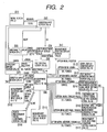
- FIG. 2 is a flowchart showing an example of processing flow in accordance with the present invention for measuring a body to be inspected using the optical measurement system shown in FIG. 1. Operation of the optical measurement system is sequentially performed while an operator is looking at the windows, shown in FIG. 3 to FIG. 22, displayed on a window display screen of the display portion 21.
- an initial window for selecting main menu shown in FIG. 3 is displayed (S1).
- the processing proceeds to measurement processing when the button 301 is selected, the processing proceeds to data analysis when the button 302 is selected and the program is ended when the button 303 is selected.
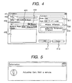
- the window for inputting conditions disappears and a window for displaying gain adjusting underway shown in FIG. 5 is displayed in the middle of the screen (S3).
- this window is always displayed at a position in the screen of the display portion 21.
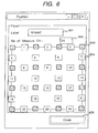
- the irradiation optical fibers 8-1 to 8-4 and the detecting optical fibers 10-1 to 10-5 shown in FIG. 1 are generally fixed in a helmet to be put on by the person to be inspected. Therefore, if measuring channel numbers are indicated on the helmet to make the positional relationship between the number shown by the reference character 602 in FIG. 6, recognition of the operator is further assisted.
- the reference character 601 is a part for displaying the selected measuring mode, the displayed window for displaying measured positions corresponds to the measuring mode.
- the reference character 602 is a part for displaying number of measuring channels of the measured plane.
- the reference character 603 indicates the setting positions of the irradiation and the detecting optical fibers, that is, the irradiation positions and the detecting positions.
- the reference character 604 indicates the measuring channel numbers, and the measuring channel number is displayed in green color when the automatic gain adjustment of the measuring channel is well performed.
- the measuring channel number of the measuring channel is displayed in red color. Further, in this case, a window for display abnormality shown in FIG. 7 is displayed near the window for displaying measured positions shown in Fig. 6 (S5).
- the case where the gain adjustment is failed means that there is possibly a problem in a measured position in the right-hand side or the left-hand side or the upper side or the down side of the channel displayed in red color. Since it is considered that there is a problem in setting of the optical fiber when the red-colored display appears, the optical fiber is required to be reset. Therefore, after resetting the optical fiber, the reference character 701 in FIG. 7 is used when the measurement is aborted by returning to the window of FIG. 3 or FIG. 4.
- the window for display abnormality is deleted and the window for displaying gain adjusting underway is displayed to perform the automatic gain adjustment again.
- the window for displaying gain adjusting underway shown in FIG. 5 is deleted, and the abnormal measuring channel in the window for displaying measured positions shown in FIG. 6 is displayed in red color, and the window for displaying abnormality shown in FIG. 7 is displayed near the window for displaying measured positions shown in FIG. 6.
- the window for displaying gain adjusting underway shown in FIG. 5 is deleted, and all the measuring channels in the window for displaying measured positions shown in FIG. 6 are changed to green color, and a window for forming a file shown in FIG. 8 is displayed.
- the reference character 703 is a button which is pushed when the abnormality is neglected.
- the window for forming a file is displayed (S6) by neglecting the abnormal measuring channel in the window for displaying measured positions shown in FIG. 6 (remaining the red colored display as it is).
- the window for forming a file shown in FIG. 8 is displayed in the middle of the display screen regardless of presence and absence of abnormality, and the position of the window for displaying measured positions shown in FIG. 6 is moved to a lower left position in the display screen as the window for forming a file shown in FIG. 8 is displayed.
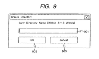
- the window for creating directory shown in FIG. 9 is displayed (S7).
- the reference character 901 is a part for inputting name of a directory to be created
- the reference character 902 is a button for completing directory creation
- the reference character 903 is a cancel button.
- FIG. 8 when the button 805 is pushed, the window for forming a file shown in FIG. 8 is deleted, and a measurement window shown in FIG. 10 is displayed an upper left portion of the display screen (S8), and a window or windows for displaying measurement data time sequence shown in FIG. 14 is or are displayed in a large portion in the right side of the display screen (S11).
- FIG. 8 is used for controlling execution of measurement.
- meaning and function of each part are as follows.
- a measurement condition corresponding to a selected measurement mode is displayed.
- the measurement condition expresses correspondence to a measuring channel (measuring position), a channel of A/D converter, a wavelength, a signal amplification and so on. Further, specifying of a channel to measure and specifying a channel to display may be possible. Furthermore, it is possible to instruct to input another signal into a vacant channel.
- meaning and function of each part are as follows.
- checking and setting change can be easily performed because the monitor of the measurement conditions (1203 to 1208) and the conditions of graph display (1202) are shown on the single window. Further, a signal of another measurement instrument (apparatus) can be acquired using this window. Furthermore, the window of FIG. 12 is only one window that the operator inputs used conditions by selecting necessity of measuring input signals.
- FIG. 15 (the window for inputting the display conditions of graph of FIG. 14) (S12)
- FIG. 16 (the window for inputting a file backup condition) (S13)
- This window is for setting the condition of function of backup data during measurement at any time by assuming a case of a power outage during measuring or a case where a file specified by the window for forming a file of FIG. 8 is damaged due to some causes.
- FIG. 17 (The window for input setting of the other measurement equipment output signal) (S14)
- a signal output from another measurement instrument is acquired from data of a vacant A/D converter channel.
- a channel number of the A/D converter used at acquiring the data, a name of kind of the signal (EEG and so on) and a dynamic ramge of the A/D converter are selected.
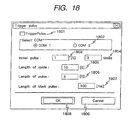
- a rectangular wave voltage signal is periodically output from the present optical measurement system.
- the other measurement instruments a brain wave meter and so on
- the measuring time can be strictly set in agreement between the instruments.
- the rectangular wave signal is output from, for example, a serial board of a personal computer.
- the first kind is a rectangular wave signal which is output only at starting of measurement.
- the second kind is a rectangular wave signal which is periodically output until the measurement is completed.
- the third kind is a rectangular wave signal which is output in synchronism with pushing of the mark button of FIG. 10. The condition of these three kinds of rectangular wave signals can be set by the window of FIG. 18.
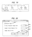
- FIG. 20 (The window for setting an external input trigger synchronous measurement condition) (S16)
- This window is a window which is used when measurement is performed in synchronism with a trigger signal from the external. By performing synchronous measurement, the time is completely in synchronism with the other measurement instrument and a stimulation apparatus.
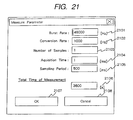
- FIG. 21 (the window for setting a measured data acquiring condition) (S17)
- a channel operating frequency of the A/D converter (Burst Rate), a sampling frequency per one channel of the A/D converter (Conversion Rate), an average number of adding times of acquired data (number of Samples), an adding time of acquired data (Acquisition Time), a data acquisition time interval (Sampling Period: the same as the part 1003 of FIG. 10) and a total measuring time can be set.
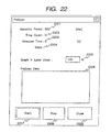
- FIG. 22 (The window for checking a measured signal) (S18)
- This window is used for that the operator checks the state of signals by performing pre-measurement in prior to starting the actual measurement, if necessary.
- a value of signal displayed in the graph is expressed by a voltage value.
- an operator even if not skilled, can perform input work speedily and without error. Further, there are provided the option functions which can be set by an operator.
- an optical measurement system which is suitable for optically measuring a body to be inspected and easily obtaining an image of a desired item based on information obtained by the measurement.
- an operator even if not skilled, can perform input work speedily and without error. Accordingly, the operator can perform the optical measurement operation even if he is not understand the operating manual very well.
Landscapes
- Health & Medical Sciences (AREA)
- Life Sciences & Earth Sciences (AREA)
- Physics & Mathematics (AREA)
- Pathology (AREA)
- General Health & Medical Sciences (AREA)
- Engineering & Computer Science (AREA)
- Animal Behavior & Ethology (AREA)
- Veterinary Medicine (AREA)
- Heart & Thoracic Surgery (AREA)
- Medical Informatics (AREA)
- Molecular Biology (AREA)
- Surgery (AREA)
- Biophysics (AREA)
- Biomedical Technology (AREA)
- Public Health (AREA)
- Spectroscopy & Molecular Physics (AREA)
- Neurology (AREA)
- Human Computer Interaction (AREA)
- Optics & Photonics (AREA)
- Chemical & Material Sciences (AREA)
- Analytical Chemistry (AREA)
- Biochemistry (AREA)
- General Physics & Mathematics (AREA)
- Immunology (AREA)
- Measurement Of The Respiration, Hearing Ability, Form, And Blood Characteristics Of Living Organisms (AREA)
- Investigating Or Analysing Materials By Optical Means (AREA)
- Spectrometry And Color Measurement (AREA)
Abstract
Claims (11)
- Système de mesure optique comportant :une pluralité de parties d'irradiation de lumière, de la lumière provenant desdites parties d'irradiation de lumière étant irradiée sur un corps à examiner,une pluralité de parties de détection pour détecter de la lumière provenant dudit corps à examiner,une partie d'affichage pour afficher des images destinées à indiquer des positions desdites parties d'irradiation ou desdites parties de détection, etune partie d'affichage pour afficher des images pour indiquer des positions de mesure situées entre lesdites parties d'irradiation et lesdites parties de détection,caractérisé par des moyens pour détecter qu'une partie d'irradiation particulière ou une partie de détection particulière ne possède pas une fonction d'irradiation ou de détection et pour changer l'image indiquant une desdites positions de mesure correspondant à ladite partie d'irradiation et à ladite partie de détection.
- Système selon la revendication 1, comportant de plus sur un écran :une partie de spécification (405) pour spécifier un mode sélectionné,une partie d'affichage pour afficher le nombre de points de mesure, etune partie d'affichage de position de mesure constituée de parties destinées à afficher une position de mesure et l'état du numéro d'allocation affecté à ladite position de mesure.
- Système selon la revendication 2, comportant de plus sur un écran :une partie d'affichage de mesure (1005) pour afficher des données de séquence temporelle de mesure,une partie pour établir une condition d'acquisition de données,une partie (1006) pour afficher un état d'acquisition desdites données,une partie d'instruction pour ordonner une commande de mesure, etune partie d'instruction de marque (1011) pour apposer une marque à une position sur ladite partie d'instruction de mesure.
- Système selon la revendication 3, dans lequel ladite partie pour établir une condition d'acquisition de données comporte :une partie (1003) pour spécifier et afficher un intervalle de temps d'acquisition de données par un signal lumineux provenant d'un corps à examiner,une partie d'affichage (1004) pour indiquer le nombre d'acquisitions desdites données, etune partie d'affichage (1010) pour indiquer un laps de temps de mesure desdites données.
- Système selon la revendication 3, dans lequel ladite partie d'instruction pour ordonner une commande de mesure comporte :une partie (1007) pour ordonner l'initiation d'une mesure,une partie (1008) pour ordonner l'achèvement d'acquisition desdites données, etune partie (1009) pour ordonner l'achèvement d'un examen de mesure.
- Système selon la revendication 3, dans lequel ladite partie d'affichage de mesure (1005) est affichée en grand et conçue de manière à ne pas être chevauchée par ladite partie d'affichage de position de mesure, ladite partie pour établir une condition d'acquisition de données, ladite partie (1006) pour afficher un état d'acquisition desdites données, ladite partie d'instruction pour ordonner une commande de ladite mesure et ladite partie d'instruction de marque (1011).
- Système selon la revendication 2, comportant de plus une partie d'affichage d'anomalie.
- Système selon la revendication 7, dans lequel ladite partie d'affichage d'anomalie comporte :une partie d'instruction (701) pour achever une opération en cours,une partie d'instruction (702) pour ordonner un ajustement de gain à nouveau, etune partie d'instruction (703) pour ordonner de continuer l'opération en négligeant l'apparition d'une anomalie.
- Système selon la revendication 7, dans lequel ladite partie d'affichage de position de mesure est agencée dans une partie centrale dudit écran.
- Système selon la revendication 3, comportant de plus une partie d'affichage d'instruction de mesure expérimentale par des signaux réels, dans lequel ladite partie d'affichage d'instruction de mesure expérimentale comporte de préférence au moins une partie d'instruction (1501) pour ordonner un grossissement d'un graphique.
- Système selon la revendication 2, comportant de plus une partie d'affichage ou un traitement pour indiquer une période au cours de laquelle le gain est ajusté.
Applications Claiming Priority (3)
| Application Number | Priority Date | Filing Date | Title |
|---|---|---|---|
| JP13464998 | 1998-04-28 | ||
| JP13464998A JP4006826B2 (ja) | 1998-04-28 | 1998-04-28 | 生体光計測装置 |
| PCT/JP1999/002207 WO1999056108A1 (fr) | 1998-04-28 | 1999-04-26 | Instrument et procede de mesure optique |
Publications (3)
| Publication Number | Publication Date |
|---|---|
| EP1076236A1 EP1076236A1 (fr) | 2001-02-14 |
| EP1076236A4 EP1076236A4 (fr) | 2001-10-17 |
| EP1076236B1 true EP1076236B1 (fr) | 2007-02-21 |
Family
ID=15133317
Family Applications (1)
| Application Number | Title | Priority Date | Filing Date |
|---|---|---|---|
| EP19990917155 Expired - Lifetime EP1076236B1 (fr) | 1998-04-28 | 1999-04-26 | Instrument de mesure optique |
Country Status (5)
| Country | Link |
|---|---|
| US (2) | US7047149B1 (fr) |
| EP (1) | EP1076236B1 (fr) |
| JP (1) | JP4006826B2 (fr) |
| DE (1) | DE69935214T2 (fr) |
| WO (1) | WO1999056108A1 (fr) |
Families Citing this family (25)
| Publication number | Priority date | Publication date | Assignee | Title |
|---|---|---|---|---|
| WO2004021889A1 (fr) | 2002-09-05 | 2004-03-18 | Hitachi Medical Corporation | Dispositif photometrique de corps vivant |
| JP4517613B2 (ja) * | 2003-09-19 | 2010-08-04 | 株式会社日立メディコ | 生体信号処理装置 |
| US8160667B2 (en) | 2003-11-26 | 2012-04-17 | Hitachi Medical Corporation | Biological light measuring apparatus and method |
| JP4590555B2 (ja) | 2004-09-02 | 2010-12-01 | 国立大学法人長岡技術科学大学 | 感性状態判別方法及び装置 |
| JP4839171B2 (ja) * | 2006-09-29 | 2011-12-21 | 株式会社日立メディコ | 生体光計測装置 |
| US8457705B2 (en) * | 2006-10-25 | 2013-06-04 | University Of Denver | Brain imaging system and methods for direct prosthesis control |
| FR2914743B1 (fr) | 2007-04-06 | 2009-05-15 | Michelin Soc Tech | Procede de detection et d'estimation d'un phenomene d'hydroplanage d'un pneumatique sur une chaussee mouillee |
| US8636670B2 (en) | 2008-05-13 | 2014-01-28 | The Invention Science Fund I, Llc | Circulatory monitoring systems and methods |
| US9717896B2 (en) | 2007-12-18 | 2017-08-01 | Gearbox, Llc | Treatment indications informed by a priori implant information |
| US20090287120A1 (en) | 2007-12-18 | 2009-11-19 | Searete Llc, A Limited Liability Corporation Of The State Of Delaware | Circulatory monitoring systems and methods |
| JP5281805B2 (ja) * | 2008-02-20 | 2013-09-04 | 株式会社日立メディコ | 生体光計測装置の検査用ファントム装置 |
| WO2010038774A1 (fr) * | 2008-10-01 | 2010-04-08 | 株式会社 日立メディコ | Dispositif de mesure d’une lumière biologique et procédé d’affichage de position pour afficher une position d’irradiation de lumière et une position de détection de lumière, ou canal de mesure |
| JP4961442B2 (ja) * | 2009-02-02 | 2012-06-27 | 株式会社日立製作所 | 生体計測用プローブ及び生体光計測装置 |
| US8419641B2 (en) * | 2009-02-13 | 2013-04-16 | Hitachi Medical Corporation | Medical image display method, medical image diagnostic apparatus, and medical image display device |
| WO2010116964A1 (fr) | 2009-04-08 | 2010-10-14 | 株式会社 日立メディコ | Biophotomètre et procédé pour déterminer la déconnexion d'une fibre optique |
| KR101148769B1 (ko) * | 2009-06-02 | 2012-05-24 | 주식회사 인포피아 | 복수의 생체 데이터를 측정할 수 있는 측정장치, 생체 데이터 측정방법 및 이를 위한 측정 스트립 |
| CN102469993B (zh) * | 2009-07-21 | 2014-07-16 | 株式会社岛津制作所 | 生物体光测量装置 |
| US8583565B2 (en) * | 2009-08-03 | 2013-11-12 | Colorado Seminary, Which Owns And Operates The University Of Denver | Brain imaging system and methods for direct prosthesis control |
| CN103562708A (zh) * | 2011-04-08 | 2014-02-05 | Abb研究有限公司 | 分析仪器及其操作方法 |
| CN103528989B (zh) * | 2013-10-30 | 2018-10-02 | 合肥汇众知识产权管理有限公司 | 近红外水分测量仪 |
| CN104614070B (zh) * | 2015-01-06 | 2017-01-04 | 国家电网公司 | 一种多光谱测量的光资源监测方法及系统 |
| CN104833348B (zh) * | 2015-04-30 | 2017-07-14 | 长安大学 | 一种基于静态力矩模式陀螺全站仪的逐次多位置寻北测量方法 |
| JP2017041159A (ja) * | 2015-08-21 | 2017-02-23 | 株式会社日立製作所 | 機器診断システム |
| JP6609738B2 (ja) * | 2016-02-10 | 2019-11-27 | 株式会社NeU | 生体光計測装置及び生体光計測方法 |
| USD840426S1 (en) * | 2017-09-13 | 2019-02-12 | Inspire Medical Systems, Inc. | Display screen or portion thereof with animated graphical user interface |
Family Cites Families (23)
| Publication number | Priority date | Publication date | Assignee | Title |
|---|---|---|---|---|
| JPS6072542A (ja) | 1983-09-28 | 1985-04-24 | 株式会社島津製作所 | 光線ct装置 |
| JPS62231625A (ja) | 1986-03-31 | 1987-10-12 | 住友電気工業株式会社 | 光ctスキヤナ装置 |
| JPH0752040B2 (ja) | 1986-07-03 | 1995-06-05 | 三洋電機株式会社 | 吸収冷凍機 |
| JPS6315005A (ja) | 1986-07-04 | 1988-01-22 | Soichi Arakawa | 火葬台車 |
| JPS63277038A (ja) | 1987-05-08 | 1988-11-15 | Hamamatsu Photonics Kk | 診断装置 |
| JPH01202384A (ja) | 1988-02-04 | 1989-08-15 | Fanuc Ltd | レーザ電源の調整方法 |
| US4975636A (en) * | 1989-05-01 | 1990-12-04 | Hewlett-Packard Company | Method and apparatus for selecting and displaying a high resolution window from a main display |
| US5039937A (en) * | 1990-05-11 | 1991-08-13 | Nicolet Instrument Corporation | Method and apparatus for providing compressed and expanded displays on a digital oscilloscope |
| US5161535A (en) * | 1991-06-24 | 1992-11-10 | Hewlett-Packard Company | Medical ultrasound imaging system having a partitioned menu |
| JPH05300887A (ja) * | 1992-04-27 | 1993-11-16 | Shimadzu Corp | 脳血液量測定装置 |
| US5853370A (en) * | 1996-09-13 | 1998-12-29 | Non-Invasive Technology, Inc. | Optical system and method for non-invasive imaging of biological tissue |
| EP0614645A4 (fr) | 1992-08-31 | 1996-04-03 | Hitachi Ltd | Appareil de tomographie optique informatisee. |
| JPH06154227A (ja) * | 1992-11-20 | 1994-06-03 | Terumo Corp | 超音波診断装置 |
| JP3239553B2 (ja) | 1993-09-20 | 2001-12-17 | 株式会社島津製作所 | 脳機能解析装置 |
| JP3465327B2 (ja) | 1993-11-12 | 2003-11-10 | カシオ計算機株式会社 | 心電波検出装置、心電波検出システム、および、脈拍演算装置 |
| US5517105A (en) * | 1994-10-25 | 1996-05-14 | Tektronix, Inc. | Dual linked zoom boxes for instrument display |
| DE69627477T2 (de) | 1995-01-03 | 2004-03-18 | Non-Invasive Technology, Inc. | Optische koppelvorrichtung zur in-vivo untersuchung von biologischen geweben |
| JP3629583B2 (ja) | 1995-05-18 | 2005-03-16 | 株式会社キーエンス | データ収集装置、監視装置及び記録媒体 |
| JP3682793B2 (ja) * | 1995-11-30 | 2005-08-10 | 株式会社日立製作所 | 光による散乱体内部画像化装置 |
| JPH0998972A (ja) | 1995-10-06 | 1997-04-15 | Hitachi Ltd | 生体光計測装置及び画像作成方法 |
| US6240309B1 (en) | 1995-10-06 | 2001-05-29 | Hitachi, Ltd. | Optical measurement instrument for living body |
| JPH09262217A (ja) | 1996-03-28 | 1997-10-07 | Matsushita Electric Works Ltd | 携帯型心電図記録装置 |
| JP3728019B2 (ja) | 1996-07-02 | 2005-12-21 | 株式会社日立メディコ | 医用画像診断装置 |
-
1998
- 1998-04-28 JP JP13464998A patent/JP4006826B2/ja not_active Expired - Lifetime
-
1999
- 1999-04-26 EP EP19990917155 patent/EP1076236B1/fr not_active Expired - Lifetime
- 1999-04-26 DE DE1999635214 patent/DE69935214T2/de not_active Expired - Lifetime
- 1999-04-26 US US09/674,008 patent/US7047149B1/en not_active Expired - Fee Related
- 1999-04-26 WO PCT/JP1999/002207 patent/WO1999056108A1/fr active IP Right Grant
-
2006
- 2006-03-20 US US11/378,448 patent/US7359825B2/en not_active Expired - Fee Related
Also Published As
| Publication number | Publication date |
|---|---|
| EP1076236A1 (fr) | 2001-02-14 |
| JPH11311599A (ja) | 1999-11-09 |
| DE69935214D1 (de) | 2007-04-05 |
| JP4006826B2 (ja) | 2007-11-14 |
| EP1076236A4 (fr) | 2001-10-17 |
| US20060178839A1 (en) | 2006-08-10 |
| US7047149B1 (en) | 2006-05-16 |
| DE69935214T2 (de) | 2007-12-20 |
| US7359825B2 (en) | 2008-04-15 |
| WO1999056108A1 (fr) | 1999-11-04 |
Similar Documents
| Publication | Publication Date | Title |
|---|---|---|
| EP1076236B1 (fr) | Instrument de mesure optique | |
| US6542763B1 (en) | Optical measurement equipment and recording medium and optical measurement method | |
| JP4076003B2 (ja) | 生体光計測装置 | |
| US6611698B1 (en) | Optical measuring instrument | |
| US7463916B2 (en) | Optical measurement apparatus for living body | |
| JPH0998972A (ja) | 生体光計測装置及び画像作成方法 | |
| US7725145B2 (en) | Biological photometric device | |
| EP1154257B1 (fr) | Dispositif de mesure optique | |
| JP4332534B2 (ja) | 生体光計測装置 | |
| JP2006297125A (ja) | 生体光計測装置 | |
| CN110123281A (zh) | 基于锁相光子计数技术的并行激励扩散光学层析成像装置 | |
| US5586554A (en) | Optical system for measuring metabolism in a body | |
| JP5790877B2 (ja) | 光生体測定システム及びその使用方法 | |
| JP4478724B2 (ja) | 光計測装置 | |
| JP4156585B2 (ja) | 光計測装置 | |
| JP2005111283A (ja) | 光計測装置 | |
| JPH07120384A (ja) | 光計測方法および装置 | |
| CN109596525B (zh) | 一种检测组织活性的实时测量方法和仪器 | |
| JP2006187306A (ja) | 生体信号処理装置 | |
| JP2003075331A (ja) | 生体光計測装置及びその装置における画像作成方法 | |
| JP6281628B2 (ja) | 光計測システム | |
| JP2002372491A (ja) | 生体光計測装置の信号表示方法 | |
| JPWO2020162062A1 (ja) | 脳機能計測装置 |
Legal Events
| Date | Code | Title | Description |
|---|---|---|---|
| PUAI | Public reference made under article 153(3) epc to a published international application that has entered the european phase |
Free format text: ORIGINAL CODE: 0009012 |
|
| 17P | Request for examination filed |
Effective date: 20001124 |
|
| AK | Designated contracting states |
Kind code of ref document: A1 Designated state(s): DE FR GB IT |
|
| RIC1 | Information provided on ipc code assigned before grant |
Free format text: 7G 01N 21/17 A, 7A 61B 10/00 B, 7G 01N 21/47 B, 7A 61B 5/00 B |
|
| A4 | Supplementary search report drawn up and despatched |
Effective date: 20010830 |
|
| AK | Designated contracting states |
Kind code of ref document: A4 Designated state(s): DE FR GB IT |
|
| 17Q | First examination report despatched |
Effective date: 20040601 |
|
| GRAP | Despatch of communication of intention to grant a patent |
Free format text: ORIGINAL CODE: EPIDOSNIGR1 |
|
| RTI1 | Title (correction) |
Free format text: OPTICAL MEASUREMENT INSTRUMENT |
|
| GRAS | Grant fee paid |
Free format text: ORIGINAL CODE: EPIDOSNIGR3 |
|
| GRAA | (expected) grant |
Free format text: ORIGINAL CODE: 0009210 |
|
| RAP1 | Party data changed (applicant data changed or rights of an application transferred) |
Owner name: HITACHI MEDICAL CORPORATION Owner name: HITACHI, LTD. |
|
| AK | Designated contracting states |
Kind code of ref document: B1 Designated state(s): DE FR GB IT |
|
| REG | Reference to a national code |
Ref country code: GB Ref legal event code: FG4D |
|
| REF | Corresponds to: |
Ref document number: 69935214 Country of ref document: DE Date of ref document: 20070405 Kind code of ref document: P |
|
| ET | Fr: translation filed | ||
| PLBE | No opposition filed within time limit |
Free format text: ORIGINAL CODE: 0009261 |
|
| STAA | Information on the status of an ep patent application or granted ep patent |
Free format text: STATUS: NO OPPOSITION FILED WITHIN TIME LIMIT |
|
| 26N | No opposition filed |
Effective date: 20071122 |
|
| PGFP | Annual fee paid to national office [announced via postgrant information from national office to epo] |
Ref country code: FR Payment date: 20100416 Year of fee payment: 12 |
|
| REG | Reference to a national code |
Ref country code: FR Ref legal event code: ST Effective date: 20111230 |
|
| PG25 | Lapsed in a contracting state [announced via postgrant information from national office to epo] |
Ref country code: FR Free format text: LAPSE BECAUSE OF NON-PAYMENT OF DUE FEES Effective date: 20110502 |
|
| PGFP | Annual fee paid to national office [announced via postgrant information from national office to epo] |
Ref country code: IT Payment date: 20150415 Year of fee payment: 17 |
|
| PGFP | Annual fee paid to national office [announced via postgrant information from national office to epo] |
Ref country code: GB Payment date: 20160420 Year of fee payment: 18 Ref country code: DE Payment date: 20160419 Year of fee payment: 18 |
|
| PG25 | Lapsed in a contracting state [announced via postgrant information from national office to epo] |
Ref country code: IT Free format text: LAPSE BECAUSE OF NON-PAYMENT OF DUE FEES Effective date: 20160426 |
|
| REG | Reference to a national code |
Ref country code: DE Ref legal event code: R119 Ref document number: 69935214 Country of ref document: DE |
|
| GBPC | Gb: european patent ceased through non-payment of renewal fee |
Effective date: 20170426 |
|
| PG25 | Lapsed in a contracting state [announced via postgrant information from national office to epo] |
Ref country code: DE Free format text: LAPSE BECAUSE OF NON-PAYMENT OF DUE FEES Effective date: 20171103 |
|
| PG25 | Lapsed in a contracting state [announced via postgrant information from national office to epo] |
Ref country code: GB Free format text: LAPSE BECAUSE OF NON-PAYMENT OF DUE FEES Effective date: 20170426 |