EP1075007A1 - Elektrischer Drucktastenschalter - Google Patents
Elektrischer Drucktastenschalter Download PDFInfo
- Publication number
- EP1075007A1 EP1075007A1 EP00114687A EP00114687A EP1075007A1 EP 1075007 A1 EP1075007 A1 EP 1075007A1 EP 00114687 A EP00114687 A EP 00114687A EP 00114687 A EP00114687 A EP 00114687A EP 1075007 A1 EP1075007 A1 EP 1075007A1
- Authority
- EP
- European Patent Office
- Prior art keywords
- contact
- switch according
- collar
- button
- contact spring
- Prior art date
- Legal status (The legal status is an assumption and is not a legal conclusion. Google has not performed a legal analysis and makes no representation as to the accuracy of the status listed.)
- Granted
Links
- 230000006835 compression Effects 0.000 claims description 5
- 238000007906 compression Methods 0.000 claims description 5
- 230000001681 protective effect Effects 0.000 claims description 4
- 238000013459 approach Methods 0.000 description 20
- 230000005489 elastic deformation Effects 0.000 description 2
- 238000009434 installation Methods 0.000 description 2
- 238000004519 manufacturing process Methods 0.000 description 2
- 238000003860 storage Methods 0.000 description 2
- 206010000496 acne Diseases 0.000 description 1
- 230000004913 activation Effects 0.000 description 1
- 230000015572 biosynthetic process Effects 0.000 description 1
- 238000013461 design Methods 0.000 description 1
- 238000011161 development Methods 0.000 description 1
- 238000006073 displacement reaction Methods 0.000 description 1
- 238000005553 drilling Methods 0.000 description 1
- 230000000694 effects Effects 0.000 description 1
- 238000005516 engineering process Methods 0.000 description 1
- 238000001746 injection moulding Methods 0.000 description 1
- 238000003780 insertion Methods 0.000 description 1
- 230000037431 insertion Effects 0.000 description 1
- 238000005304 joining Methods 0.000 description 1
- 230000002093 peripheral effect Effects 0.000 description 1
- 239000013641 positive control Substances 0.000 description 1
- 238000004080 punching Methods 0.000 description 1
- 238000004904 shortening Methods 0.000 description 1
Images

Classifications
-
- H—ELECTRICITY
- H01—ELECTRIC ELEMENTS
- H01H—ELECTRIC SWITCHES; RELAYS; SELECTORS; EMERGENCY PROTECTIVE DEVICES
- H01H13/00—Switches having rectilinearly-movable operating part or parts adapted for pushing or pulling in one direction only, e.g. push-button switch
- H01H13/02—Details
- H01H13/023—Light-emitting indicators
-
- H—ELECTRICITY
- H01—ELECTRIC ELEMENTS
- H01H—ELECTRIC SWITCHES; RELAYS; SELECTORS; EMERGENCY PROTECTIVE DEVICES
- H01H13/00—Switches having rectilinearly-movable operating part or parts adapted for pushing or pulling in one direction only, e.g. push-button switch
- H01H13/02—Details
- H01H13/12—Movable parts; Contacts mounted thereon
- H01H13/20—Driving mechanisms
-
- H—ELECTRICITY
- H01—ELECTRIC ELEMENTS
- H01H—ELECTRIC SWITCHES; RELAYS; SELECTORS; EMERGENCY PROTECTIVE DEVICES
- H01H13/00—Switches having rectilinearly-movable operating part or parts adapted for pushing or pulling in one direction only, e.g. push-button switch
- H01H13/50—Switches having rectilinearly-movable operating part or parts adapted for pushing or pulling in one direction only, e.g. push-button switch having a single operating member
- H01H13/52—Switches having rectilinearly-movable operating part or parts adapted for pushing or pulling in one direction only, e.g. push-button switch having a single operating member the contact returning to its original state immediately upon removal of operating force, e.g. bell-push switch
Definitions
- the invention relates to an electrical push button switch with one associated with an actuation approach Button and with at least one in a housing with connection contacts arranged contact from a contact track and a Contact spring, the contact spring and the contact track aligned parallel to the direction of actuation of the button are.
- an electrical push button switch is included a button which can be actuated about an eccentric axis is known, which carries a tab transmitting the actuation and with a arranged in a connection-carrying housing, provide a contact spring with a punched-out contact cable is.
- the tab on the button acts almost parallel aligned to the direction of actuation of the button, springy clamped and pivotable switching element, wherein the fulcrum of the switching element opposite the axis of the Button is located, and the switching element carries a cam that the Tongue parallel to the direction of actuation of the button clamped contact spring. So that the cam of the Switching element can act on the contact tongue is one relatively expensive storage of the switching element necessary, wherein the storage is spring-loaded and a return movement the key after the application.
- DE-U-71 38 974 discloses an electric one Push button switch with one inside a switch housing a contact rail mounted contact rocker and one around Axis actuated pushbutton.
- the bearings for the axis of rotation the feeler are off-center above and to the side of arranged the contact rail and the sensing element has a Nose on the resilient, cut free from the contact rocker Tongue of the contact rocker acts.
- DE-C-34 21 021 shows an electrical Push button switch with an operating rocker, on which two symmetrical resilient legs are molded between them a cam is attached, which alternately in two recesses a contact spring pushes, causing a pivoting the contact spring is in its opposite switching position.
- the two tabs are springy and on theirs the cam facing sides shaped such that after Completion of the actuation of the cams in its zero position returns.
- DE-A5-21 48 804 discloses a push button switch, where a push button pivots when actuated executes about an axis and the rotational movement on one rectilinear movable contact slide is transferable.
- lever-like button head On lever-like button head is made of plastic in one piece two hinged and snap-in at the free end Manufactured foot parts.
- the aforementioned push button switches all have a relatively complex Switch mechanism for redirecting the direction of actuation the button in the direction of action of a corresponding one Contact spring on.
- push button switches are known, on the button of which Actuation approach to act on a switch contact is provided.
- the Switch contact designed as a microswitch and on one aligned perpendicular to the direction of actuation of the button Printed circuit board arranged. Because of the necessary alignment the circuit board, the push button switch has a relative large cross section.
- the object is achieved in that the actuation approach the button is assigned a forced operation, that when the button is pressed, the Contact spring through the actuation approach and thus Closes the contact.
- Pushbutton switch provided due to manufacture the extremely simple switching mechanism at low cost leaves.
- a redirection of the direction of actuation of the button together the assigned actuation approach to the application the contact spring is made only by the positive guidance of the actuation approach.
- the forced operation is the closing of the contact safely by the actuation approach at Depress the button elastically in the direction of the contact spring is deformed.
- the contact spring is expedient in the area of their fixed end with one towards of the actuating approach pointing U-shaped bend.
- Manufactured lead frame thus includes both the contact spring as well as the contact path.
- the U-shaped bend of the contact spring causes a shortening of the stretched length as well a slight bend in the same, causing the free end the contact spring in an area above the assigned Contact path is located.
- the formation of the contact path and the contact spring in a lead frame provides a relative easy handling of these contact elements during production the push button switch safely.
- a light-emitting diode serves as a search and Functional lighting and another LED shows the Activation of an anti-theft alarm system of a motor vehicle on.
- the contacts in one piece with the lead frame molded and surrounded by a protective collar.
- Punching grid at least partially in the middle of a floor of the housing vertically molded web.
- the lead frame is overmolded in a plastic injection molding process, at the same time the web and the bottom are formed.
- the web is slidable in opposite guide grooves collar associated with the button.
- the Collar on the inside of the actuation approach which in the is substantially L-shaped, the end face of the short leg formed on the inside of the collar and the front of the long leg is a switch cam to act on the contact spring.
- This is the elastic deformation of the actuation approach at one Actuation of the button to act on the contact spring ensured, the switch cam for a sufficient Contact surface on the contact spring ensures.
- the web on its narrow sides opposite stops for the collar of the button If the collar on the stops of the bridge is the lower end of the switching path reached.
- the web has on the side on which the contact spring is arranged, the Positive guidance for the actuation approach, the opposite and spaced-apart L-shaped guide lugs includes, the end faces of the long legs the web are fixed and the bevelled short leg grasp the actuation shoulder and guide it.
- the management approaches expediently embrace the Switch cams formed on the free end of the actuating attachment, which comes to rest on the contact spring.
- draws the forced operation is characterized by a simple design and can be molded in one piece with the web.
- the contact spring is in the effective area of the actuating approach with a transverse groove or a punctiform Increase.
- the transverse groove or the point elevation represent a resistance to the actuation approach, the to be overcome when the button is pressed and also is tactile perceptible as a switching threshold.
- the collar points the button on the circumferential webs, in corresponding Grooves of the housing are guided.
- the webs are as Installation coding formed, which is why assembly errors due incorrect insertion of the collar into the housing is excluded are.
- the collar of the button expediently points to the bottom facing end face a nose for receiving a compression spring on, one end of which is on the associated end face of the collar and the other end of which is supported on the ground.
- This compression spring supports the restoring effect of the contact spring. However, it is not absolutely necessary.
- the push button switch 1 designed as a warning light switch comprises a key 2, the surface of which is backlit Symbol 3 is provided and the one at the bottom Collar 4 wears.
- the collar 4 is in a recess of the button 2 used and by means of peripheral knobs 5 in corresponding Bores 6 of the key 2 set.
- a housing 7 with side clip arms 8 for attachment in a corresponding Installation opening of a motor vehicle surrounds the Collar 4, which has opposite webs 9, which are inserted into assigned grooves of the housing 7.
- the molded on opposite side surfaces of the collar 4 Bars 9 are dimensioned differently, which is why the correct Joining the collar 4 and the housing 7 ensured is.
- the housing 7 is on the opposite of the key 2 Side closed by a bottom 10, the clip openings 11 of the housing 7 engaging clip lugs 12.
- On the bottom 10 is a connection contacts 13 surrounding Protective collar 14.
- a web 15 is formed on the floor 10 perpendicular to this, which extends into the collar 4 of the button 2 and there slidably inserted in opposite guide grooves 16 is.
- a lead frame 45 is formed in the web 15, the contact tracks 17 arranged parallel to one another, 18, 19, 20 and a contact spring associated with the contact track 18 21 includes.
- the contact tracks 17, 18, 19, 20 and Contact spring 21 are parallel to the direction of actuation Key 2 aligned and each have a connection contact 13 on.
- the contact spring 21 is with a U-shaped bend 22 provided from the stretched length of the contact spring 21 causes a displacement of the free end 23, after which the free end 23 to lie above the contact track 18 is coming. Furthermore, the U-shaped bend 22 supports the spring action the contact spring 21.
- the web 15 has a clamping device 26 for the connecting contacts 27 of the light-emitting diodes 24, 25 on.
- the web 15 is a positive guide 28 for one end Switching cams 29 having actuation projection 30 of the Collar 4 assigned to button 2, the two L-shaped guide lugs 31 includes.
- the guide lugs 30 are opposite and receiving the contact spring 21 between them each with the end face 32 of its long leg 33 the web 15 set.
- the short legs 34 of the guide lugs 30 are provided with bevels 35 and embrace the switching cam 29 of the actuating projection 30.
- the actuating projection 30 is essentially L-shaped and with the end face 36 of the short leg 37 molded onto the inside 38 of the collar 4.
- the front 39 of the long leg 40 of the actuating projection 30 carries the Switch cam 29, the long leg 40 approximately parallel is aligned with the inside 38 of the collar 4.
Landscapes
- Push-Button Switches (AREA)
Abstract
Description
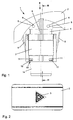
- Fig.1
- eine Seitenansicht eines erfindungsgemäßen Drucktastenschalters,
- Fig.2
- eine Ansicht auf die Darstellung nach Fig. 1 in Richtung des Pfeils II,
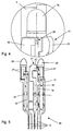
- Fig.3
- einen vergrößerten Schnitt durch die Darstellung nach Fig. 1 gemäß der Linie III-III,
- Fig.4
- eine vergrößerte Darstellung einer Einzelheit IV nach Fig. 3 und
- Fig.5
- eine um 90° gedrehte Einzeldarstellung des Stanzgitters nach Fig. 3 im verkleinerten Maßstab.
- 1.
- Taste
- 2.
- Symbol
- 3.
- Kragen
- 4.
- Noppen
- 5.
- Bohrung
- 6.
- Gehäuse
- 7.
- Klipsarm
- 8.
- Steg
- 9.
- Boden
- 10.
- Klipsöffnung
- 11.
- Klipsnase
- 12.
- Anschlußkontakt
- 13.
- Schutzkragen
- 14.
- Steg
- 15.
- Führungsnut
- 16.
- Kontaktbahn
- 17.
- Kontaktbahn
- 18.
- Kontaktbahn
- 19.
- Kontaktbahn
- 20.
- Kontaktfeder
- 21.
- U-förmige Abwinklung
- 22.
- freies Ende
- 23.
- Leuchtdiode
- 24.
- Leuchtdiode
- 25.
- Klemmeinrichtung
- 26.
- Anschlußkontakt
- 27.
- Zwangsführung
- 28.
- Schaltnocken
- 29.
- Betätigungsansatz
- 30.
- Führungsansatz
- 31.
- Stirnseite
- 32.
- langer Schenkel
- 33.
- kurzer Schenkel
- 34.
- Abschrägung
- 35.
- Stirnseite
- 36.
- kurzer Schenkel
- 37.
- Innenseite
- 38.
- Stirnseite
- 39.
- langer Schenkel
- 40.
- Kontakt
- 41.
- Druckfeder
- 42.
- Nase
- 43.
- Pfeil
- 44.
- Stanzgitter
Claims (16)
- Elektrischer Drucktastenschalter mit einer mit einem Betätigungsansatz (30) verbundenen Taste (2) und mit mindestens einem in einem Gehäuse (7) mit Anschlußkontakten (13) angeordneten Kontakt (41) aus einer Kontaktbahn (18) und einer Kontaktfeder (21), wobei die Kontaktfeder (21) sowie die Kontaktbahn (18) parallel zur Betätigungsrichtung der Taste (2) ausgerichtet sind, dadurch gekennzeichnet, daß dem Betätigungsansatz (30) der Taste (2) eine Zwangsführung (28) zugeordnet ist, die bei einer Betätigung der Taste (2) eine Beaufschlagung der Kontaktfeder (21) durch den Betätigungsansatz (30) und damit ein Schließen des Kontaktes (41) bewirkt.
- Elektrischer Drucktastenschalter nach Anspruch 1, dadurch gekennzeichnet, daß die Kontaktfeder (21) und die Kontaktbahn (18) Kontaktelemente eines gemeinsamen Stanzgitters (45) sind, deren freie Enden (23) sich überlappen und deren feste Enden nebeneinander angeordnet sind.
- Elektrischer Drucktastenschalter nach Anspruch 1 oder 2, dadurch gekennzeichnet, daß die Kontaktfeder (21) und die Kontaktbahn (18) im wesentlichen parallel zueinander angeordnet sind.
- Elektrischer Drucktastenschalter nach einem der Ansprüche 1 bis 3, dadurch gekennzeichnet, daß die Kontaktfeder (21) im Bereich ihres festen Endes mit einer in Richtung des Betätigungsansatzes (30) weisenden U-förmigen Abwinklung (22) versehen ist.
- Elektrischer Drucktastenschalter nach einem der Ansprüche 1 bis 4, dadurch gekennzeichnet, daß der Kontaktbahn (18) des Kontaktes (41) weitere Kontaktbahnen (17, 19, 20) des Stanzgitters (45) zur Beaufschlagung von Leuchtdioden (24, 25) zugeordnet sind.
- Elektrischer Drucktastenschalter nach Anspruch 1, dadurch gekennzeichnet, daß die Anschlußkontakte (13) einstückig mit dem Stanzgitter (45) ausgeformt und von einem Schutzkragen (14) umgeben sind.
- Elektrischer Drucktastenschalter nach einem der Ansprüche 1 bis 6, dadurch gekennzeichnet, daß das Stanzgitter (45) zumindest teilweise in einen mittig an einem Boden (10) des Gehäuses (7) senkrecht angeformten Steg (15) eingelassen ist.
- Elektrischer Drucktastenschalter nach Anspruch 7, dadurch gekennzeichnet, daß der Steg (15) verschiebbar in gegenüberliegende Führungsnuten (16) eines mit der Taste (2) verbundenen Kragens (4) eingesetzt ist.
- Elektrischer Drucktastenschalter nach Anspruch 8, dadurch gekennzeichnet, daß der Kragen (4) auf seiner Innenseite (38) den Betätigungsansatz (30) trägt, der im wesentlichen L-förmig ausgebildet ist, wobei die Stirnseite (36) des kurzen Schenkels (37) an der Innenseite (38) des Kragens (4) angeformt ist und die Stirnseite (39) des langen Schenkels (40) einen Schaltnocken (29) zur Beaufschlagung der Kontaktfeder (21) trägt.
- Elektrischer Drucktastenschalter nach Anspruch 7 oder 8, dadurch gekennzeichnet, daß der Steg (15) an seinen Schmalseiten gegenüberliegende Anschläge für den Kragen (4) der Taste (2) aufweist.
- Elektrischer Drucktastenschalter nach einem der Ansprüche 7 bis 10, dadurch gekennzeichnet, daß der Steg (15) auf der Seite, auf der die Kontaktfeder (21) angeordnet ist, die Zwangsführung (28) für den Betätigungsansatz (30) aufweist, die gegenüberliegende sowie zueinander beabstandete L-förmige Führungsansätze (31) umfaßt, wobei die Stirnseiten (32) der langen Schenkel (33) auf dem Steg (15) festgelegt sind und die mit Abschrägungen (35) versehenen kurzen Schenkel (34) den Betätigungsansatz (30) umgreifen und zwangsführen.
- Elektrischer Drucktastenschalter nach Anspruch 11, dadurch gekennzeichnet, daß die Führungsansätze (31) den am freien Ende des Betätigungsansatzes (30) angeformten Schaltnocken (29) umgreifen, der auf der Kontaktfeder (21) zur Anlage kommt.
- Elektrischer Drucktastenschalter nach Anspruch 11, dadurch gekennzeichnet, daß auf der den Führungsansätzen (31) gegenüberliegenden Seite des Steges (15) eine Erhöhung ausgeformt ist, die mit einem am Kragen (4) der Taste (2) angeformten Klipsarm zusammenwirkt.
- Elektrischer Drucktastenschalter nach einem der Ansprüche 1 bis 13, dadurch gekennzeichnet, daß die Kontaktfeder (21) im Wirkbereich des Betätigungsansatzes (30) mit einer Querrille oder einer punktuellen Erhöhung versehen ist.
- Elektrischer Drucktastenschalter nach einem der Ansprüche 1 bis 14, dadurch gekennzeichnet, daß der Kragen (4) der Taste (2) umfangsseitige Stege (9) aufweist, die in korrespondierenden Nuten des Gehäuses (7) geführt sind.
- Elektrischer Drucktastenschalter nach einem der Ansprüche 1 bis 15, dadurch gekennzeichnet, daß der Kragen (4) der Taste (2) an der dem Boden (10) zugewandten Stirnseite eine Nase (43) zur Aufnahme einer Druckfeder (42) aufweist, deren eines Ende sich an der zugeordneten Stirnseite des Kragens (4) und deren anderes Ende sich am Boden (10) abstützt.
Applications Claiming Priority (2)
| Application Number | Priority Date | Filing Date | Title |
|---|---|---|---|
| DE19936195A DE19936195C1 (de) | 1999-07-31 | 1999-07-31 | Elektrischer Drucktastenschalter |
| DE19936195 | 1999-07-31 |
Publications (2)
| Publication Number | Publication Date |
|---|---|
| EP1075007A1 true EP1075007A1 (de) | 2001-02-07 |
| EP1075007B1 EP1075007B1 (de) | 2002-10-02 |
Family
ID=7916820
Family Applications (1)
| Application Number | Title | Priority Date | Filing Date |
|---|---|---|---|
| EP00114687A Expired - Lifetime EP1075007B1 (de) | 1999-07-31 | 2000-07-08 | Elektrischer Drucktastenschalter |
Country Status (2)
| Country | Link |
|---|---|
| EP (1) | EP1075007B1 (de) |
| DE (2) | DE19936195C1 (de) |
Cited By (1)
| Publication number | Priority date | Publication date | Assignee | Title |
|---|---|---|---|---|
| CN105023785A (zh) * | 2014-04-21 | 2015-11-04 | 星电株式会社 | 按压开关 |
Families Citing this family (2)
| Publication number | Priority date | Publication date | Assignee | Title |
|---|---|---|---|---|
| DE10062072A1 (de) * | 2000-12-13 | 2002-07-04 | Bosch Gmbh Robert | Stanzgitter mit Kontaktfeder |
| EP1267372A1 (de) * | 2001-06-15 | 2002-12-18 | GE Power Controls Italia S.p.a. | Integrierte Beleuchtungseinheiten zur Befestigung an Signal- und Steuervorrichtungen für elektrische Steuerpults und dergleichen |
Citations (2)
| Publication number | Priority date | Publication date | Assignee | Title |
|---|---|---|---|---|
| DE9110485U1 (de) * | 1991-08-24 | 1991-10-02 | Blaupunkt-Werke Gmbh, 3200 Hildesheim | Klapptastenanordnung für einen Tippschalter |
| EP0789927A1 (de) * | 1994-11-02 | 1997-08-20 | EATON CONTROLS GmbH & Co. KG | Elektrischer tastschalter |
Family Cites Families (4)
| Publication number | Priority date | Publication date | Assignee | Title |
|---|---|---|---|---|
| DE2148804C2 (de) * | 1971-09-30 | 1978-05-11 | Grundig E.M.V. Elektro-Mechanische Versuchsanstalt Max Grundig, 8510 Fuerth | Drucktastenschalter, insbesondere mehrfach-drucktastenschalter |
| DE3421021A1 (de) * | 1984-06-06 | 1985-12-12 | Fa. Albrecht Jung, 5885 Schalksmühle | Stoessellagerung eines elektrischen tastschalters |
| JPH0658773B2 (ja) * | 1988-10-21 | 1994-08-03 | 富士電機株式会社 | 小型開閉器 |
| DE19501856C1 (de) * | 1995-01-23 | 1996-08-01 | Kostal Leopold Gmbh & Co Kg | Elektrischer Drucktastenschalter |
-
1999
- 1999-07-31 DE DE19936195A patent/DE19936195C1/de not_active Expired - Fee Related
-
2000
- 2000-07-08 DE DE50000586T patent/DE50000586D1/de not_active Expired - Lifetime
- 2000-07-08 EP EP00114687A patent/EP1075007B1/de not_active Expired - Lifetime
Patent Citations (2)
| Publication number | Priority date | Publication date | Assignee | Title |
|---|---|---|---|---|
| DE9110485U1 (de) * | 1991-08-24 | 1991-10-02 | Blaupunkt-Werke Gmbh, 3200 Hildesheim | Klapptastenanordnung für einen Tippschalter |
| EP0789927A1 (de) * | 1994-11-02 | 1997-08-20 | EATON CONTROLS GmbH & Co. KG | Elektrischer tastschalter |
Cited By (1)
| Publication number | Priority date | Publication date | Assignee | Title |
|---|---|---|---|---|
| CN105023785A (zh) * | 2014-04-21 | 2015-11-04 | 星电株式会社 | 按压开关 |
Also Published As
| Publication number | Publication date |
|---|---|
| DE19936195C1 (de) | 2000-12-07 |
| DE50000586D1 (de) | 2002-11-07 |
| EP1075007B1 (de) | 2002-10-02 |
Similar Documents
| Publication | Publication Date | Title |
|---|---|---|
| EP0553694A2 (de) | Elektrischer Schalter | |
| EP0957498A2 (de) | Fensterheberschalter | |
| EP3850650A1 (de) | Tastenmodul für eine tastatur, tastatur und verfahren zum versehen eines tastenstössels mit einem drahtbügel | |
| DE2337904A1 (de) | Eingabe-taste | |
| DE2233170A1 (de) | Tastschalter mit einem in einem gehaeuse verschiebbaren tastenstoessel | |
| EP1075007B1 (de) | Elektrischer Drucktastenschalter | |
| WO2014131576A1 (de) | Drucktastenschalter | |
| DE4312771A1 (de) | Zweistufentaster | |
| DE19627294A1 (de) | Wipptaster | |
| DE4229756A1 (de) | Elektrisches Schaltgerät | |
| DE2835256C2 (de) | Schiebeschalter, insbesondere zur Anordnung im Schalthebelende eines Lenkstockschalters | |
| DE4439008C2 (de) | Elektrischer Tastschalter | |
| EP0708464B1 (de) | Elektrischer Schalter | |
| DE2050784A1 (de) | Schalter und diesen verwendende Tastatur | |
| DE3411597C2 (de) | Schiebeschalter | |
| EP1281586B1 (de) | Lenkrad mit beweglichem Gassackmodul | |
| EP0614204A2 (de) | Schalterkappe für Drucktastenschalter | |
| DE3037448C2 (de) | Drucktaster | |
| DE19916795C1 (de) | Druckschalter | |
| EP0831509A2 (de) | Antriebssystem für Schalter, insbesondere für Relais | |
| DE102007009006A1 (de) | Tastschalter für ein Kraftfahrzeug | |
| EP3734629B1 (de) | Schalt-vorrichtung | |
| DE19614297A1 (de) | Elektrisches Installationsgerät | |
| DE7929209U1 (de) | Kodierender Schiebeschalter | |
| EP1151447B1 (de) | Kontaktfeder-einheit für einen elektrischen schalter |
Legal Events
| Date | Code | Title | Description |
|---|---|---|---|
| PUAI | Public reference made under article 153(3) epc to a published international application that has entered the european phase |
Free format text: ORIGINAL CODE: 0009012 |
|
| AK | Designated contracting states |
Kind code of ref document: A1 Designated state(s): DE ES FR GB IT |
|
| AX | Request for extension of the european patent |
Free format text: AL;LT;LV;MK;RO;SI |
|
| 17P | Request for examination filed |
Effective date: 20010725 |
|
| AKX | Designation fees paid |
Free format text: DE ES FR GB IT |
|
| GRAG | Despatch of communication of intention to grant |
Free format text: ORIGINAL CODE: EPIDOS AGRA |
|
| 17Q | First examination report despatched |
Effective date: 20011228 |
|
| GRAG | Despatch of communication of intention to grant |
Free format text: ORIGINAL CODE: EPIDOS AGRA |
|
| GRAH | Despatch of communication of intention to grant a patent |
Free format text: ORIGINAL CODE: EPIDOS IGRA |
|
| GRAH | Despatch of communication of intention to grant a patent |
Free format text: ORIGINAL CODE: EPIDOS IGRA |
|
| RAP1 | Party data changed (applicant data changed or rights of an application transferred) |
Owner name: DELPHI TECHNOLOGIES INC. |
|
| GRAA | (expected) grant |
Free format text: ORIGINAL CODE: 0009210 |
|
| AK | Designated contracting states |
Kind code of ref document: B1 Designated state(s): DE ES FR GB IT |
|
| PG25 | Lapsed in a contracting state [announced via postgrant information from national office to epo] |
Ref country code: IT Free format text: LAPSE BECAUSE OF FAILURE TO SUBMIT A TRANSLATION OF THE DESCRIPTION OR TO PAY THE FEE WITHIN THE PRESCRIBED TIME-LIMIT;WARNING: LAPSES OF ITALIAN PATENTS WITH EFFECTIVE DATE BEFORE 2007 MAY HAVE OCCURRED AT ANY TIME BEFORE 2007. THE CORRECT EFFECTIVE DATE MAY BE DIFFERENT FROM THE ONE RECORDED. Effective date: 20021002 |
|
| REG | Reference to a national code |
Ref country code: GB Ref legal event code: FG4D Free format text: NOT ENGLISH |
|
| REF | Corresponds to: |
Ref document number: 50000586 Country of ref document: DE Date of ref document: 20021107 |
|
| GBT | Gb: translation of ep patent filed (gb section 77(6)(a)/1977) |
Effective date: 20030127 |
|
| ET | Fr: translation filed | ||
| PG25 | Lapsed in a contracting state [announced via postgrant information from national office to epo] |
Ref country code: ES Free format text: LAPSE BECAUSE OF FAILURE TO SUBMIT A TRANSLATION OF THE DESCRIPTION OR TO PAY THE FEE WITHIN THE PRESCRIBED TIME-LIMIT Effective date: 20030429 |
|
| PLBE | No opposition filed within time limit |
Free format text: ORIGINAL CODE: 0009261 |
|
| STAA | Information on the status of an ep patent application or granted ep patent |
Free format text: STATUS: NO OPPOSITION FILED WITHIN TIME LIMIT |
|
| 26N | No opposition filed |
Effective date: 20030703 |
|
| REG | Reference to a national code |
Ref country code: DE Ref legal event code: R082 Ref document number: 50000586 Country of ref document: DE Representative=s name: JOCHEN MUELLER, DE Ref country code: DE Ref legal event code: R082 Ref document number: 50000586 Country of ref document: DE Representative=s name: MUELLER, JOCHEN, DIPL.-ING., DE |
|
| REG | Reference to a national code |
Ref country code: FR Ref legal event code: PLFP Year of fee payment: 16 |
|
| REG | Reference to a national code |
Ref country code: FR Ref legal event code: PLFP Year of fee payment: 17 |
|
| PGFP | Annual fee paid to national office [announced via postgrant information from national office to epo] |
Ref country code: GB Payment date: 20160727 Year of fee payment: 17 Ref country code: DE Payment date: 20160726 Year of fee payment: 17 |
|
| PGFP | Annual fee paid to national office [announced via postgrant information from national office to epo] |
Ref country code: FR Payment date: 20160726 Year of fee payment: 17 |
|
| REG | Reference to a national code |
Ref country code: DE Ref legal event code: R119 Ref document number: 50000586 Country of ref document: DE |
|
| GBPC | Gb: european patent ceased through non-payment of renewal fee |
Effective date: 20170708 |
|
| REG | Reference to a national code |
Ref country code: FR Ref legal event code: ST Effective date: 20180330 |
|
| PG25 | Lapsed in a contracting state [announced via postgrant information from national office to epo] |
Ref country code: GB Free format text: LAPSE BECAUSE OF NON-PAYMENT OF DUE FEES Effective date: 20170708 Ref country code: DE Free format text: LAPSE BECAUSE OF NON-PAYMENT OF DUE FEES Effective date: 20180201 |
|
| PG25 | Lapsed in a contracting state [announced via postgrant information from national office to epo] |
Ref country code: FR Free format text: LAPSE BECAUSE OF NON-PAYMENT OF DUE FEES Effective date: 20170731 |