EP1074232B1 - Vorrichtung zur Photokoagulation - Google Patents
Vorrichtung zur Photokoagulation Download PDFInfo
- Publication number
- EP1074232B1 EP1074232B1 EP00116798A EP00116798A EP1074232B1 EP 1074232 B1 EP1074232 B1 EP 1074232B1 EP 00116798 A EP00116798 A EP 00116798A EP 00116798 A EP00116798 A EP 00116798A EP 1074232 B1 EP1074232 B1 EP 1074232B1
- Authority
- EP
- European Patent Office
- Prior art keywords
- coagulation
- spot
- irradiation
- laser
- time
- Prior art date
- Legal status (The legal status is an assumption and is not a legal conclusion. Google has not performed a legal analysis and makes no representation as to the accuracy of the status listed.)
- Expired - Lifetime
Links
Images


Classifications
-
- A—HUMAN NECESSITIES
- A61—MEDICAL OR VETERINARY SCIENCE; HYGIENE
- A61F—FILTERS IMPLANTABLE INTO BLOOD VESSELS; PROSTHESES; DEVICES PROVIDING PATENCY TO, OR PREVENTING COLLAPSING OF, TUBULAR STRUCTURES OF THE BODY, e.g. STENTS; ORTHOPAEDIC, NURSING OR CONTRACEPTIVE DEVICES; FOMENTATION; TREATMENT OR PROTECTION OF EYES OR EARS; BANDAGES, DRESSINGS OR ABSORBENT PADS; FIRST-AID KITS
- A61F9/00—Methods or devices for treatment of the eyes; Devices for putting-in contact lenses; Devices to correct squinting; Apparatus to guide the blind; Protective devices for the eyes, carried on the body or in the hand
- A61F9/007—Methods or devices for eye surgery
- A61F9/008—Methods or devices for eye surgery using laser
- A61F9/00821—Methods or devices for eye surgery using laser for coagulation
-
- A—HUMAN NECESSITIES
- A61—MEDICAL OR VETERINARY SCIENCE; HYGIENE
- A61F—FILTERS IMPLANTABLE INTO BLOOD VESSELS; PROSTHESES; DEVICES PROVIDING PATENCY TO, OR PREVENTING COLLAPSING OF, TUBULAR STRUCTURES OF THE BODY, e.g. STENTS; ORTHOPAEDIC, NURSING OR CONTRACEPTIVE DEVICES; FOMENTATION; TREATMENT OR PROTECTION OF EYES OR EARS; BANDAGES, DRESSINGS OR ABSORBENT PADS; FIRST-AID KITS
- A61F9/00—Methods or devices for treatment of the eyes; Devices for putting-in contact lenses; Devices to correct squinting; Apparatus to guide the blind; Protective devices for the eyes, carried on the body or in the hand
- A61F9/007—Methods or devices for eye surgery
- A61F9/008—Methods or devices for eye surgery using laser
-
- A—HUMAN NECESSITIES
- A61—MEDICAL OR VETERINARY SCIENCE; HYGIENE
- A61B—DIAGNOSIS; SURGERY; IDENTIFICATION
- A61B17/00—Surgical instruments, devices or methods, e.g. tourniquets
- A61B2017/00017—Electrical control of surgical instruments
-
- A—HUMAN NECESSITIES
- A61—MEDICAL OR VETERINARY SCIENCE; HYGIENE
- A61F—FILTERS IMPLANTABLE INTO BLOOD VESSELS; PROSTHESES; DEVICES PROVIDING PATENCY TO, OR PREVENTING COLLAPSING OF, TUBULAR STRUCTURES OF THE BODY, e.g. STENTS; ORTHOPAEDIC, NURSING OR CONTRACEPTIVE DEVICES; FOMENTATION; TREATMENT OR PROTECTION OF EYES OR EARS; BANDAGES, DRESSINGS OR ABSORBENT PADS; FIRST-AID KITS
- A61F9/00—Methods or devices for treatment of the eyes; Devices for putting-in contact lenses; Devices to correct squinting; Apparatus to guide the blind; Protective devices for the eyes, carried on the body or in the hand
- A61F9/007—Methods or devices for eye surgery
- A61F9/008—Methods or devices for eye surgery using laser
- A61F2009/00844—Feedback systems
-
- A—HUMAN NECESSITIES
- A61—MEDICAL OR VETERINARY SCIENCE; HYGIENE
- A61F—FILTERS IMPLANTABLE INTO BLOOD VESSELS; PROSTHESES; DEVICES PROVIDING PATENCY TO, OR PREVENTING COLLAPSING OF, TUBULAR STRUCTURES OF THE BODY, e.g. STENTS; ORTHOPAEDIC, NURSING OR CONTRACEPTIVE DEVICES; FOMENTATION; TREATMENT OR PROTECTION OF EYES OR EARS; BANDAGES, DRESSINGS OR ABSORBENT PADS; FIRST-AID KITS
- A61F9/00—Methods or devices for treatment of the eyes; Devices for putting-in contact lenses; Devices to correct squinting; Apparatus to guide the blind; Protective devices for the eyes, carried on the body or in the hand
- A61F9/007—Methods or devices for eye surgery
- A61F9/008—Methods or devices for eye surgery using laser
- A61F2009/00861—Methods or devices for eye surgery using laser adapted for treatment at a particular location
- A61F2009/00863—Retina
Definitions
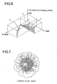
- Fig. 7 shows a schematic image of an eye fundus with a number of coagulation spots produced.
- a photocoagulation apparatus according to sections 1-3 of claim 1 can be taken.
- the apparatus further comprises a memory for storing such treatment parameters as position of the coagulation, the cut and the cornia, the power of the laser beam and the treatment time period. These parameters are stored for the intended use and for the actual use. In DI automatic termination may be provided when white discoloration has reacted a certain level.
- the present invention has been made in view of the above circumstances and has an object to overcome the above problems and to provide a photocoagulation apparatus which simply is operable by an operator to produce coagulation spots each being uniform in color and spotsize in an effected part to be treated irrespective of light-absorbing property of the tissue of the effected part to be treated.
- Fig. 1 is a perspective view of the photocoagulation apparatus, which is used for ophthalmic operations in the present embodiment. It is to be noted that irradiation of a treatment laser beam is hereinafter referred to as a laser irradiation.
- Numeral 1 is a main unit which accommodates a laser source (a laser oscillator) 10 mentioned later, a laser delivery optical system, and others.
- Numeral 3 is a control unit used for setting necessary laser irradiation conditions such as laser irradiation power, laser irradiation time, etc.
- Numeral 4 is a slit-lamp delivery for irradiating a treatment laser beam (which is hereinafter simply referred to as a treatment beam) to an affected part of a patient's eye E, while allowing an operator to observe the eye E.
- a treatment laser beam which is hereinafter simply referred to as a treatment beam
- the slit-lamp delivery 4 is constructed of a laser irradiation unit 5 for irradiating the treatment beam delivered therein from the laser source 10 through an optical fiber 2 to the eye E, an illumination unit 6 for slit-illuminating the patient's eye E, and a binocular microscope 4a.
- Numeral 7 is a cable used for transmitting video signals from a CCD camera (a photoelectric image pick-up device) 47 installed in the microscope 4a to a video image processing section 51 provided in the main unit 1.
- Numeral 8 is a footswitch used for generating a trigger signal to start laser irradiation.
- Fig. 2 is a schematic structural view of an optical system and a control system of the photocoagulation apparatus in the present embodiment.
- Numeral 10 is a laser source which emits a treatment beam.
- an Nd:YAG laser capable of oscillating a fundamental wavelength of 1064nm is used to generate a green light of 532nm (linearly polarized light) which is double the fundamental wavelength.
- Numeral 14 is a beam splitter for transmitting the major part of the treatment beam from the laser source 10 and reflecting a part of the treatment beam. The part of the treatment beam reflected by the beam splitter 14 passes through a diffusion plate 15 into a power sensor 16. Thus, the power sensor 16 can detect the power of the treatment beam emitted from the laser source 10.
- Numeral 17 is a first safety shutter, which is inserted on the optical path of the treatment beam in order to intercept the beam in cases for example of occurrence of an abnormal event.
- Numeral 18 is a dichroic mirror.
- Numeral 19 is a laser source which emits an aiming light. As this laser source 19 in the present embodiment, a semiconductor laser which emits a red light is used. An aiming laser beam (which is simply hereinafter referred to as an aiming beam) emitted from the laser source 19 passes through a collimator lens 20 and then the collimated aiming beam is made coaxial with the treatment beam reflected by the dichroic mirror 18.
- Numeral 21 is a second safety shutter, which is put on the optical path during non-emission of the aiming beam. After passing by the shutter 21 positioned out of the optical path, the coaxial laser beams (the treatment beam and the aiming beam) are condensed by a condensing lens 22 to an entrance surface 2a of the fiber 2.
- the laser beams delivered through the fiber 2 to the laser irradiation unit 5 is allowed to pass through a relay lens 24, zoom lenses 25, and an objective lens 26, and then is reflected by a movable mirror 27 toward a contact lens 28 put on the patient's eye E.
- the laser beams are thus irradiated to the affected part of the eye E.
- the zoom lenses 25 are movable in a direction of the optical axis for changing a spot size of the laser beams irradiated onto the affected part.
- an illumination light emitted from an illumination source 30 passes through a condensing lens 31, a slit plate 32, a projection lens 33, and then is reflected by splitting mirrors 35a and 35b toward the eye E.
- the eye E is thus illuminated through the contact lens 28.
- the splitting mirrors 35a and 35b are adopted to split the illumination light so as not to intercept the optical path of the laser beams reflected by or passed through the movable mirror 27.
- Numeral 34 is a correcting lens for correcting a length of the optical path of the illumination light to be reflected by the splitting mirror 35a.
- the binocular microscope 4a is internally provided with an objective lens 40, variable magnification lenses 41, a protective filter 42, a group of erect prisms 43, a field diaphragm 44, and eyepieces 45. These components are arranged in pairs for binocular observation, only one of which is illustrated in Fig. 2.
- a half mirror 46 is also disposed on an observing optical path between the erect prism 43 and the field diaphragm 44 in either one of the paired components. The light reflected by the half mirror 46 will be received by the CCD camera 47.
- Numeral 51 is a video image processing section including a memory for recording a forming state (progress) of the coagulation spot photographed by the camera 47.
- this camera 47 photographs the area of the eye fundus including the affected part
- the image processing section 51 takes (extracts) the image data of the coagulation spot from the image data of the photographed area of the eye fundus for the purpose of comparison and analysis of coagulation spots.
- the section 51 makes a comparison and analysis between the recorded forming state of the coagulation spot and a forming state of a coagulation spot produced by subsequent laser irradiation.
- the section 51 transmits the analytical data to a control section 50.
- This control section 50 controls the laser source 10 based on the laser irradiation conditions set on the control unit 3 and the analytical data on the forming state of the coagulation spot transmitted from the video image processing section 51.
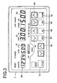
- Fig. 3 is a plane view of the control unit 3.
- Numeral 60 is a counter display part which displays the total number of emissions of the treatment beam.
- Numeral 61 is a spot diameter display part which displays the spot diameter (spot size) of the treatment beam to be irradiated to the affected part. This spot diameter is changeable in 10 ⁇ m step in the 50-500 ⁇ m range by operation of a change knob not illustrated.
- Numeral 62 is a time display part which displays the time duration of laser irradiation which is set by operation of time setting keys 64. That is to say, upon press of the footswitch 8 to generate a trigger signal, causing the start of laser irradiation, the laser irradiation is performed only for the time set with the time setting keys 64.
- Numeral 63 is a power display part which displays the power of the treatment beam to be irradiated, which is set with power setting keys 65.
- Numeral 66 is an aiming control key used for adjustment of the luminous intensity of the aiming beam.
- Numeral 67 is an INTERVAL switch used for setting a time interval between emissions of the treatment beam irradiated continually. The time interval can be changed in 0.2 sec. step in a range of 0.2 to 1.0 sec.
- Numeral 68 is a SET switch used for storing a forming state of a coagulation spot produced in the fundus of the eye E by laser irradiation, in the video image processing section 51.
- the control section 50 can control the laser irradiation power, the laser irradiation time, etc. so as to produce a coagulation spot with substantially the same forming state as that of the coagulation spot recorded in the video image processing section 51. The detail thereof will be mentioned later.
- a TIME switch 69 is used.
- a POWER switch 70 is used.
- Numeral 71 is a STATUS switch used for switching between a laser irradiation enabled status and a laser irradiation disabled status.
- the operator first observes the fundus of the eye E through the microscope 4a, the eye E being illuminated by the illumination light emitted from the illumination unit 6, and operates the aiming control keys 66 to turn on the aiming light source 19.
- the control section 50 causes the shutter 21 to move out of the optical path.
- the operator observing the aiming beam irradiated to the eye fundus, operates a joystick 9 arranged on the operator's side (see Fig. 1) or an unillustrated manipulator to make alignment of the apparatus with respect to the affected part of the eye E. Subsequently, the laser irradiation conditions are determined; the operator sets a spot diameter of the treatment beam with an unillustrated change knob and sets irradiation time, irradiation power, time interval, etc. with the corresponding switches or keys on the control unit 3. The set conditions are determined according to the conditions of the affected part based on the operator's experiences.
- the operator After determination of the laser irradiation conditions, the operator adjusts the aiming beam to the irradiation site (the affected part) and presses the footswitch 8 to generate a trigger signal to start the laser irradiation, the trigger signal being transmitted to the control section 50.
- the control section 50 controls the laser source 10 to emit the treatment beam based on the set laser irradiation conditions to irradiate the fundus of the eye E, thus producing a coagulation spot therein.
- the operator stops pressing the footswitch 8 to temporarily stop the laser irradiation for confirmation of the forming state of the coagulation spot.
- the operator After stop of the laser irradiation, the operator should observe the forming state of the coagulation spot, and reconsider and change the laser irradiation conditions if needed.
- the operator presses the SET switch 68 and then operates the apparatus to perform laser irradiation, under the same laser irradiation conditions as in the above last irradiation, with respect to a site (an affected part) which has almost the same light-absorbing property as the previously irradiated site.
- the video image processing section 51 starts to record the image data transmitted from the camera 47.
- the operator stops the laser irradiation and presses the SET switch 68 again, causing the image processing section 51 to stop recording the image data.
- the image processing section 51 checks variations with time in color and spot size of the coagulation spot from the laser irradiation start in infinitesimal time intervals, and records those variations as a desired forming state of a coagulation spot.
- the color of the coagulation spot is generally white.
- the image processing section 51 thus uses the degree of shade of white as a factor to compare the colors between the coagulation spots.
- Fig. 4 is a flowchart of the laser irradiation control executed with the TIME switch 69 set.
- Fig. 5 is a flowchart of the laser irradiation performed with the POWER switch 70 set.
- Fig. 6 is a graph of showing a relationship between forming states (the rate of coagulation) of coagulation spots in relation to irradiation time and irradiation power.
- a curve X shows a proper forming state of a coagulation spot which has been recorded in the memory of the video image processing section 51
- a curve Y shows a forming state of a coagulation spot produced by the laser irradiation at the adjusted power and the same irradiation time as that for the coagulation spot X
- a curve Z shows a forming state of a coagulation spot produced by the laser irradiation at the adjusted irradiation time and the same irradiation power as that for the coagulation spot X.
- the TIME switch 69 The case of using the TIME switch 69 is first explained. After the record of the desired forming state of the coagulation spot with use of the SET switch 68 as described above, the operator presses the TIME switch 69 and then the footswitch 8 to start the laser irradiation (S1). Upon start of the laser irradiation, the image processing section 51 compares, in infinitesimal time intervals, the variations with time in color and spot size of the coagulation spot being produced in the fundus of the eye E with those of the coagulation spot previously produced and recorded as above (S2). This comparison is started from the irradiation start time. The positions of the coagulation spots to be compared may be identified by detecting the sites of which image states vary with time in the images of the area photographed by the camera 47.
- the image processing section 51 continuously transmits analytical data on differences in color and spot size between the coagulation spots in infinitesimal time intervals.
- the control section 50 controls the laser irradiation based on the analytical data transmitted from the image processing section 51 so that the forming state of the current coagulation spot corresponds all the time to the desired forming state of the coagulation spot recorded in advance. Namely, when the coagulation spot is identical in color and spot size to the recorded one (S4: YES), the control section 50 controls the laser source 10 to continuously emit the treatment beam at current power (S5). Alternatively, when NO in S4, the control section 50 adjusts the power of the treatment beam to be emitted from the laser source 10 (S6).
- a coagulation spot having a predetermined color and spot size could not be produced within the set time.
- the progress of the coagulating state (color and spot size) is measured, and the power of the laser is controlled to increase sufficiently to produce a coagulation spot having a predetermined color and spot size.
- the case of using the POWER switch 70 is explained below, referring to Fig. 5.
- the operator presses the POWER switch 70 and then the footswitch 8 to start the laser irradiation (S11).
- the image processing section 51 compares, in infinitesimal time intervals, the variations with time in color and spot size of the coagulation spot in process of being produced in the fundus of the eye E with those of the coagulation spot recorded in advance (S12).
- the image processing section 51 continuously transmits analytical data on the coagulation spots compared in infinitesimal time intervals to the control section 50. Based on the analytical data transmitted from the image processing section 51, the control section 50 checks whether the coagulation spot in process of being produced (namely, the current coagulation spot) is identical in color and spot size to the recorded coagulation spot (S13). If NO in S13, the control section 50 operates to continue the laser irradiation at constant power (S14).
- the POWER switch 70 When the POWER switch 70 is pressed as above, maintaining the treatment beam to be irradiated at constant power, the laser source 10 is not needed continuously adjusting and a load on the apparatus can be reduced.
- the control of the laser irradiation power and the control of the laser irradiation time are of different advantages respectively.
- the operator may choose an appropriate one of the controls as needed.
- the laser irradiation conditions are adjusted so as to produce a coagulation spot with a forming state identical to the desired forming state of the coagulation spot produced and recorded in advance. Accordingly, even if sites having different light-absorbing properties to the treatment beam are irradiated, the coagulation spots can be produced with a uniform forming state without the need of changing the laser irradiation conditions every time.
- the controls of the laser irradiation power and the laser irradiation time are preferably needed to have some upper limitations in irradiation power and irradiation time to prevent the application of loads on the patient.
- the laser irradiation control is performed during irradiation of the treatment beam based on the image data of the photographed eye fundus according to variations with time of the coagulation spot.
- the laser irradiation is carried out without changing irradiation power and time during laser irradiation, and then the forming state of the coagulation spot is compared with the desired forming state of the coagulation spot recorded in advance to adjust laser irradiation conditions as needed for the subsequent laser irradiation.
- either the irradiation power or the irradiation time is used as a factor of the laser irradiation control. Both the irradiation power and the irradiation time may be controlled at the same time.
- the image processing section 51 takes (extracts) the coagulation spot portion from the image data of the photographed eye fundus to perform record, comparison and analysis of the forming state of the coagulation spot.
- An alternative manner is to cause the image analyzing section (image processing section) to take (extract) only the coagulation spot portion from the image data of the eye fundus photographed by the CCD camera and the control section to make record and analysis thereof.
- the photocoagulation apparatus in the above embodiment according to the present invention is arranged capable of recognizing the forming state of the coagulation spot by laser irradiation and adjusting the laser irradiation conditions based on the recognized results.
- substantially uniform coagulation spots can be produced irrespective of the light-absorbing properties of tissue of the affected part according to sites therein, enabling a reduction in load on the operator.
Landscapes
- Health & Medical Sciences (AREA)
- Ophthalmology & Optometry (AREA)
- Heart & Thoracic Surgery (AREA)
- Vascular Medicine (AREA)
- Optics & Photonics (AREA)
- Surgery (AREA)
- Engineering & Computer Science (AREA)
- Biomedical Technology (AREA)
- Physics & Mathematics (AREA)
- Nuclear Medicine, Radiotherapy & Molecular Imaging (AREA)
- Life Sciences & Earth Sciences (AREA)
- Animal Behavior & Ethology (AREA)
- General Health & Medical Sciences (AREA)
- Public Health (AREA)
- Veterinary Medicine (AREA)
- Laser Surgery Devices (AREA)
Claims (7)
- Photokoagolationsgeräte zum Bilden einer Photokoagolation in einem Teil eines zu behandelnden Patienten durch Bestrahlen des Teiles mit einem Behandlungslaserstrahl, der von einem Laseroszilator (10) emittiert ist, mit:einem Eingabemittel (3) zum Einstellen von mindestens eines von Laserbestrahlungszeit und Laserbestrahlungsausgabe als ein Behandlungsparameter;einem Photographiermittel (47) zum Photographieren des Koagolationspunktes, der durch Bestrahlen mit dem Laserbehandlungsstrahl gebildet ist;einem Speicher zum Speichern von Bilddaten des Koagolationspunktes in Zusammenhang mit einem entsprechenden Behandlungsparameter als eine Referenz;einem Analysemittel zum Vergleichen von Farben zwischen Bilddaten des Koagolationspunktes, der neu durch das Photographiermittel (47) erhalten ist, und Bilddaten des Koagolationspunktes, die als Referenz gespeichert sind; undeinem Steuermittel (50) zum Ändern des Behandlungsparameters auf der Grundlage eines Resultates der Analyse durch das Analysemittel (51).
- Koagolationsgerät nach Anspruch 1,
bei dem das Photographiermittel (47) aufweist:ein optisches Photographiersystem (47) zum Photographieren eines Gebietes einschließlich des Koagolationspunktes;einen Videobildverarbeitungsabschnitt (51) zum Verarbeiten eines Bildes des Gebietes, das von dem optischen Photographiersystem (47) photographiert ist, zum Herausnehmen von Bilddaten des Koagolationspunktes. - Photokoagolationsgerät in Anspruch 2,
bei dem der Videobildverarbeitungsabschnitt (51) ein Verarbeitungsmittel zum Herausnehmen der Bilddaten des Koagolationspunktes aus den Bildern, die vor und nach der Bestrahlung durch den Behandlungslaserstrahl photographiert sind. - Photokoagolationsgerät nach einem der Ansprüche 1 bis 3,
bei dem das Steuermittel (50) ein Befehlsmittel zum Übertragen eines Befehlssignales zum Ändern des Behandlungsparameters an eine Steuerung des Laseroszilators (10) enthält. - Photokoagolationsgerät nach einem der Ansprüche 1 bis 4
weiter mit einem Auswahlmittel (69, 70) zum Auswählen des Behandlungsparameters, der durch das Steuermittel zu ändern ist. - Photokoagolationsgerät nach einem der Ansprüche 1 bis 5,
weiter mit einem Fundusphotokoagolationsgerät, daß mit einem optischen Spaltlampensystem (4) versehen ist. - Photokoagolationsgerät nach einem der Ansprüche 1 bis 6,
bei dem das Photographiermittel (47) den Koagolationspunkt mit der Zeit in dem Ablauf der Bildung davon photographiert,
der Speicher die Bilddaten des Photokoagolationspunktes speichert, die die Änderungen mit der Zeit zeigen,
das Analysemittel (51) Änderungen mit der Zeit in der Farbe des Koagolationspunktes vergleicht und
das Steuermittel (50) den Behandlungsparameter während der Laserbestrahlung ändert.
Applications Claiming Priority (2)
| Application Number | Priority Date | Filing Date | Title |
|---|---|---|---|
| JP22189499A JP3889904B2 (ja) | 1999-08-05 | 1999-08-05 | 光凝固装置 |
| JP22189499 | 1999-08-05 |
Publications (2)
| Publication Number | Publication Date |
|---|---|
| EP1074232A1 EP1074232A1 (de) | 2001-02-07 |
| EP1074232B1 true EP1074232B1 (de) | 2003-02-05 |
Family
ID=16773846
Family Applications (1)
| Application Number | Title | Priority Date | Filing Date |
|---|---|---|---|
| EP00116798A Expired - Lifetime EP1074232B1 (de) | 1999-08-05 | 2000-08-03 | Vorrichtung zur Photokoagulation |
Country Status (4)
| Country | Link |
|---|---|
| US (1) | US6585722B1 (de) |
| EP (1) | EP1074232B1 (de) |
| JP (1) | JP3889904B2 (de) |
| DE (1) | DE60001342T2 (de) |
Families Citing this family (24)
| Publication number | Priority date | Publication date | Assignee | Title |
|---|---|---|---|---|
| US6789900B2 (en) * | 1996-11-22 | 2004-09-14 | Jozef F. Van De Velde | Scanning laser ophthalmoscope optimized for selective retinal microphotocoagulation |
| JP3881508B2 (ja) | 2000-12-04 | 2007-02-14 | 株式会社ニデック | レーザ治療装置 |
| DE10100857B4 (de) * | 2001-01-11 | 2006-05-18 | Carl Zeiss Jena Gmbh | Laserspaltlampe mit Laserstrahlungsquelle |
| US20030078567A1 (en) * | 2001-04-27 | 2003-04-24 | Giorgio Dorin | Method and apparatus for laser ThermoProtectiveTreatment(TPT) with pre-programmed variable irradiance long exposures |
| WO2003039416A1 (fr) * | 2001-11-08 | 2003-05-15 | Evgeny Nikolaevich Ananiev | Procede de destruction intracapsulaire du cristallin altere par la cataracte et procede de mise en oeuvre correspondant |
| US7766903B2 (en) * | 2003-12-24 | 2010-08-03 | The Board Of Trustees Of The Leland Stanford Junior University | Patterned laser treatment of the retina |
| JP4458839B2 (ja) * | 2003-12-25 | 2010-04-28 | 株式会社ニデック | レーザ治療装置 |
| US20060217691A1 (en) * | 2005-02-25 | 2006-09-28 | Georg Schuele | Real-time therapeutic dosimetry based on dynamic response of treated tissue |
| US7736382B2 (en) | 2005-09-09 | 2010-06-15 | Lockheed Martin Corporation | Apparatus for optical stimulation of nerves and other animal tissue |
| US8092446B2 (en) * | 2005-10-14 | 2012-01-10 | Carl Zeiss Meditec Ag | Device and method for material processing by means of laser radiation |
| US8012189B1 (en) | 2007-01-11 | 2011-09-06 | Lockheed Martin Corporation | Method and vestibular implant using optical stimulation of nerves |
| US20080077200A1 (en) * | 2006-09-21 | 2008-03-27 | Aculight Corporation | Apparatus and method for stimulation of nerves and automated control of surgical instruments |
| US8956396B1 (en) | 2005-10-24 | 2015-02-17 | Lockheed Martin Corporation | Eye-tracking visual prosthetic and method |
| US8945197B1 (en) | 2005-10-24 | 2015-02-03 | Lockheed Martin Corporation | Sight-restoring visual prosthetic and method using infrared nerve-stimulation light |
| DE102007005699A1 (de) * | 2007-02-05 | 2008-08-07 | Carl Zeiss Meditec Ag | Koagulationssystem |
| DE102007052103A1 (de) * | 2007-10-31 | 2009-05-07 | Medizinisches Laserzentrum Lübeck GmbH | Vorrichtung zur schonenden Lasertherapie der Retina |
| US20090137996A1 (en) * | 2007-11-28 | 2009-05-28 | Debenedictis Leonard C | Nonablative and ablative tissue treatment method and device |
| US9011509B2 (en) | 2007-11-30 | 2015-04-21 | Lockheed Martin Corporation | Individually optimized performance of optically stimulating cochlear implants |
| JP5443747B2 (ja) * | 2008-12-02 | 2014-03-19 | 株式会社ニデック | 眼科レーザ治療装置 |
| US8512319B2 (en) * | 2010-12-28 | 2013-08-20 | Nidek Co., Ltd. | Ophthalmic laser treatment apparatus |
| US9849034B2 (en) * | 2011-11-07 | 2017-12-26 | Alcon Research, Ltd. | Retinal laser surgery |
| JP6040688B2 (ja) * | 2012-09-28 | 2016-12-07 | 株式会社ニデック | 眼科用レーザ治療装置 |
| JP6293463B2 (ja) * | 2013-11-27 | 2018-03-14 | 株式会社トプコン | レーザ治療システム |
| US9381752B2 (en) * | 2014-03-28 | 2016-07-05 | Kyocera Document Solutions Inc. | Information processing apparatus and laser irradiation apparatus |
Family Cites Families (11)
| Publication number | Priority date | Publication date | Assignee | Title |
|---|---|---|---|---|
| DE3024169C2 (de) | 1980-06-27 | 1983-09-15 | Reginald Dipl.-Phys. Dr. 8028 Taufkirchen Birngruber | Verfahren und Vorrichtung zum Betreiben eines Photokoagulators für biologisches Gewebe |
| DE3306981C2 (de) | 1983-02-28 | 1987-11-12 | Wolfram 8048 Haimhausen Weinberg | Vorrichtung zur Photokoagulation von biologischem Gewebe |
| US4758081A (en) | 1985-07-18 | 1988-07-19 | Bausch & Lomb Incorporated | Control of laser photocoagulation using Raman radiation |
| DE3607721A1 (de) | 1986-03-08 | 1987-09-10 | Rodenstock Instr | Vorrichtung zur laserbehandlung des auges |
| US5147349A (en) | 1988-10-07 | 1992-09-15 | Spectra-Physics, Inc. | Diode laser device for photocoagulation of the retina |
| JP3255711B2 (ja) | 1992-06-10 | 2002-02-12 | 株式会社ニデック | 眼底カメラ |
| JPH06254112A (ja) | 1993-03-09 | 1994-09-13 | Kowa Co | 光凝固装置 |
| DE69533903T2 (de) | 1994-08-18 | 2005-12-08 | Carl Zeiss Meditec Ag | Mit optischer Kohärenz-Tomographie gesteuerter chirurgischer Apparat |
| DE19635998C1 (de) * | 1996-09-05 | 1998-04-23 | Zeiss Carl Jena Gmbh | Anordnung zur Laserkoagulation von unterhalb der Fundusoberfläche liegenden Retinaschichten und Verfahren zur Ermittlung von Veränderungen in tiefen Gewebeschichten der Retina |
| US5923399A (en) | 1996-11-22 | 1999-07-13 | Jozef F. Van de Velde | Scanning laser ophthalmoscope optimized for retinal microphotocoagulation |
| JPH11332905A (ja) * | 1998-05-29 | 1999-12-07 | Nidek Co Ltd | レーザ治療装置及びレーザ治療情報表示装置 |
-
1999
- 1999-08-05 JP JP22189499A patent/JP3889904B2/ja not_active Expired - Fee Related
-
2000
- 2000-08-01 US US09/630,363 patent/US6585722B1/en not_active Expired - Lifetime
- 2000-08-03 DE DE60001342T patent/DE60001342T2/de not_active Expired - Lifetime
- 2000-08-03 EP EP00116798A patent/EP1074232B1/de not_active Expired - Lifetime
Also Published As
| Publication number | Publication date |
|---|---|
| JP3889904B2 (ja) | 2007-03-07 |
| DE60001342D1 (de) | 2003-03-13 |
| EP1074232A1 (de) | 2001-02-07 |
| JP2001046417A (ja) | 2001-02-20 |
| DE60001342T2 (de) | 2003-08-21 |
| US6585722B1 (en) | 2003-07-01 |
Similar Documents
| Publication | Publication Date | Title |
|---|---|---|
| EP1074232B1 (de) | Vorrichtung zur Photokoagulation | |
| EP1080706B1 (de) | Laserbehandlungsgerät | |
| US6257722B1 (en) | Ophthalmic apparatus | |
| US6238385B1 (en) | Laser treatment apparatus | |
| US6530918B1 (en) | Laser treatment apparatus | |
| JP2002011106A (ja) | レーザ治療装置 | |
| JP4349705B2 (ja) | 光凝固装置 | |
| US6312423B1 (en) | Laser treatment apparatus | |
| JPH11309170A (ja) | レーザ治療装置 | |
| US20020120198A1 (en) | Method for assessing irradiation intensity of a laser beam, an apparatus for assessing irradiation intensity used under this method, and a laser beam irradiation system | |
| EP1044755B1 (de) | Laserbehandlungsvorrichtung | |
| JP3892984B2 (ja) | レーザ光凝固装置 | |
| US6383178B1 (en) | Laser treatment apparatus | |
| JP3842969B2 (ja) | レーザ治療装置 | |
| JP3695901B2 (ja) | レーザ治療装置 | |
| JP3961117B2 (ja) | レーザ治療装置 | |
| JPH10314212A (ja) | 光凝固装置 | |
| JP2003310653A (ja) | レーザ治療装置 | |
| JP5443747B2 (ja) | 眼科レーザ治療装置 | |
| JP4546062B2 (ja) | レーザ治療装置 | |
| JP4357602B2 (ja) | 眼底カメラ | |
| JP2001095816A (ja) | レーザ治療装置 | |
| JP3939021B2 (ja) | レーザ治療装置 | |
| JP2003284738A (ja) | レーザ治療装置 | |
| WO2019065990A1 (ja) | 眼科用レーザ治療装置 |
Legal Events
| Date | Code | Title | Description |
|---|---|---|---|
| PUAI | Public reference made under article 153(3) epc to a published international application that has entered the european phase |
Free format text: ORIGINAL CODE: 0009012 |
|
| AK | Designated contracting states |
Kind code of ref document: A1 Designated state(s): DE FR GB |
|
| AX | Request for extension of the european patent |
Free format text: AL;LT;LV;MK;RO;SI |
|
| 17P | Request for examination filed |
Effective date: 20010629 |
|
| AKX | Designation fees paid |
Free format text: DE FR GB |
|
| 17Q | First examination report despatched |
Effective date: 20011031 |
|
| GRAG | Despatch of communication of intention to grant |
Free format text: ORIGINAL CODE: EPIDOS AGRA |
|
| GRAG | Despatch of communication of intention to grant |
Free format text: ORIGINAL CODE: EPIDOS AGRA |
|
| GRAH | Despatch of communication of intention to grant a patent |
Free format text: ORIGINAL CODE: EPIDOS IGRA |
|
| GRAH | Despatch of communication of intention to grant a patent |
Free format text: ORIGINAL CODE: EPIDOS IGRA |
|
| GRAA | (expected) grant |
Free format text: ORIGINAL CODE: 0009210 |
|
| AK | Designated contracting states |
Designated state(s): DE FR GB |
|
| REG | Reference to a national code |
Ref country code: GB Ref legal event code: FG4D |
|
| REF | Corresponds to: |
Ref document number: 60001342 Country of ref document: DE Date of ref document: 20030313 Kind code of ref document: P |
|
| ET | Fr: translation filed | ||
| PLBE | No opposition filed within time limit |
Free format text: ORIGINAL CODE: 0009261 |
|
| STAA | Information on the status of an ep patent application or granted ep patent |
Free format text: STATUS: NO OPPOSITION FILED WITHIN TIME LIMIT |
|
| 26N | No opposition filed |
Effective date: 20031106 |
|
| PGFP | Annual fee paid to national office [announced via postgrant information from national office to epo] |
Ref country code: DE Payment date: 20140730 Year of fee payment: 15 |
|
| PGFP | Annual fee paid to national office [announced via postgrant information from national office to epo] |
Ref country code: FR Payment date: 20140808 Year of fee payment: 15 Ref country code: GB Payment date: 20140730 Year of fee payment: 15 |
|
| REG | Reference to a national code |
Ref country code: DE Ref legal event code: R119 Ref document number: 60001342 Country of ref document: DE |
|
| GBPC | Gb: european patent ceased through non-payment of renewal fee |
Effective date: 20150803 |
|
| REG | Reference to a national code |
Ref country code: FR Ref legal event code: ST Effective date: 20160429 |
|
| PG25 | Lapsed in a contracting state [announced via postgrant information from national office to epo] |
Ref country code: DE Free format text: LAPSE BECAUSE OF NON-PAYMENT OF DUE FEES Effective date: 20160301 Ref country code: GB Free format text: LAPSE BECAUSE OF NON-PAYMENT OF DUE FEES Effective date: 20150803 |
|
| PG25 | Lapsed in a contracting state [announced via postgrant information from national office to epo] |
Ref country code: FR Free format text: LAPSE BECAUSE OF NON-PAYMENT OF DUE FEES Effective date: 20150831 |