EP1069257B1 - Sonnenschutzanlage mit Sensorsteuerung - Google Patents
Sonnenschutzanlage mit Sensorsteuerung Download PDFInfo
- Publication number
- EP1069257B1 EP1069257B1 EP00114832A EP00114832A EP1069257B1 EP 1069257 B1 EP1069257 B1 EP 1069257B1 EP 00114832 A EP00114832 A EP 00114832A EP 00114832 A EP00114832 A EP 00114832A EP 1069257 B1 EP1069257 B1 EP 1069257B1
- Authority
- EP
- European Patent Office
- Prior art keywords
- sun protection
- protection device
- controller
- sensor
- support tube
- Prior art date
- Legal status (The legal status is an assumption and is not a legal conclusion. Google has not performed a legal analysis and makes no representation as to the accuracy of the status listed.)
- Expired - Lifetime
Links
- 230000037072 sun protection Effects 0.000 title claims description 42
- 230000001133 acceleration Effects 0.000 claims description 3
- 210000001503 joint Anatomy 0.000 claims description 3
- 238000009429 electrical wiring Methods 0.000 claims 1
- 238000012544 monitoring process Methods 0.000 abstract description 2
- 230000009993 protective function Effects 0.000 abstract 1
- 239000004744 fabric Substances 0.000 description 7
- 230000005611 electricity Effects 0.000 description 6
- 238000001514 detection method Methods 0.000 description 5
- 238000009434 installation Methods 0.000 description 4
- 239000000853 adhesive Substances 0.000 description 1
- 239000000428 dust Substances 0.000 description 1
- 238000010616 electrical installation Methods 0.000 description 1
- 230000007613 environmental effect Effects 0.000 description 1
- 230000010354 integration Effects 0.000 description 1
- 238000007789 sealing Methods 0.000 description 1
- 210000003462 vein Anatomy 0.000 description 1
- 230000000007 visual effect Effects 0.000 description 1
Images


Classifications
-
- E—FIXED CONSTRUCTIONS
- E06—DOORS, WINDOWS, SHUTTERS, OR ROLLER BLINDS IN GENERAL; LADDERS
- E06B—FIXED OR MOVABLE CLOSURES FOR OPENINGS IN BUILDINGS, VEHICLES, FENCES OR LIKE ENCLOSURES IN GENERAL, e.g. DOORS, WINDOWS, BLINDS, GATES
- E06B9/00—Screening or protective devices for wall or similar openings, with or without operating or securing mechanisms; Closures of similar construction
- E06B9/56—Operating, guiding or securing devices or arrangements for roll-type closures; Spring drums; Tape drums; Counterweighting arrangements therefor
- E06B9/68—Operating devices or mechanisms, e.g. with electric drive
-
- E—FIXED CONSTRUCTIONS
- E04—BUILDING
- E04F—FINISHING WORK ON BUILDINGS, e.g. STAIRS, FLOORS
- E04F10/00—Sunshades, e.g. Florentine blinds or jalousies; Outside screens; Awnings or baldachins
- E04F10/02—Sunshades, e.g. Florentine blinds or jalousies; Outside screens; Awnings or baldachins of flexible canopy materials, e.g. canvas ; Baldachins
- E04F10/06—Sunshades, e.g. Florentine blinds or jalousies; Outside screens; Awnings or baldachins of flexible canopy materials, e.g. canvas ; Baldachins comprising a roller-blind with means for holding the end away from a building
- E04F10/0644—Sunshades, e.g. Florentine blinds or jalousies; Outside screens; Awnings or baldachins of flexible canopy materials, e.g. canvas ; Baldachins comprising a roller-blind with means for holding the end away from a building with mechanisms for unrolling or balancing the blind
- E04F10/0659—Control systems therefor
-
- E—FIXED CONSTRUCTIONS
- E06—DOORS, WINDOWS, SHUTTERS, OR ROLLER BLINDS IN GENERAL; LADDERS
- E06B—FIXED OR MOVABLE CLOSURES FOR OPENINGS IN BUILDINGS, VEHICLES, FENCES OR LIKE ENCLOSURES IN GENERAL, e.g. DOORS, WINDOWS, BLINDS, GATES
- E06B9/00—Screening or protective devices for wall or similar openings, with or without operating or securing mechanisms; Closures of similar construction
- E06B9/24—Screens or other constructions affording protection against light, especially against sunshine; Similar screens for privacy or appearance; Slat blinds
- E06B9/26—Lamellar or like blinds, e.g. venetian blinds
- E06B9/28—Lamellar or like blinds, e.g. venetian blinds with horizontal lamellae, e.g. non-liftable
- E06B9/30—Lamellar or like blinds, e.g. venetian blinds with horizontal lamellae, e.g. non-liftable liftable
- E06B9/32—Operating, guiding, or securing devices therefor
-
- E—FIXED CONSTRUCTIONS
- E06—DOORS, WINDOWS, SHUTTERS, OR ROLLER BLINDS IN GENERAL; LADDERS
- E06B—FIXED OR MOVABLE CLOSURES FOR OPENINGS IN BUILDINGS, VEHICLES, FENCES OR LIKE ENCLOSURES IN GENERAL, e.g. DOORS, WINDOWS, BLINDS, GATES
- E06B9/00—Screening or protective devices for wall or similar openings, with or without operating or securing mechanisms; Closures of similar construction
- E06B9/56—Operating, guiding or securing devices or arrangements for roll-type closures; Spring drums; Tape drums; Counterweighting arrangements therefor
- E06B9/68—Operating devices or mechanisms, e.g. with electric drive
- E06B2009/6809—Control
- E06B2009/6818—Control using sensors
Definitions
- the invention relates to a sun protection system a sun protection curtain with at least one electrical Drive that controls the setting of the Sun protection curtain depending on several input variables automatically performs, at least one sensor for detection the wind load acting on the sun protection system as Input variable provided for the control and the control wired ready for use integrated in the sun protection system are and a supply connection preferably for connection is provided with a common household electricity network.
- the housings of the controls or the Sensors and their electrical connection lines to the Sun protection system also the visual impression for the viewer to disturb.
- a sun protection system is already known from DE 44 07 342 A1 with an integrated control and an integrated wind load sensor known. The detection of wind-excited forces in the area of the motor or a bracket does not always lead to satisfactory results.
- the object of the present invention is a Create sun protection system with an integrated Wind load sensor enables reliable detection of the wind load.
- the task is performed by a sun protection system solved according to claim 1.
- Such a sun protection system its operation, for example can be done with the help of a radio remote control Receiver is also integrated into the system, only has to mounted in the area of the window opening to be shaded and connected to the household electricity network.
- the electric one Wiring is minimal because it only has to a connection to the nearest distribution point of the Electricity network are produced.
- the one with external controls necessary configurations after interconnection also eliminated.
- a sensor for detection of the input variables wired ready for operation into the sun protection system integrated and also a supply connection preferably for connection to a common household electricity network is provided.
- Another significant advantage of integrated sensors for Detection of the wind load consists of the input variable is detected directly in the area of the sun protection system and thereby guarantees in the sense of an optimal automatic Control can be reduced to a minimum, with the achieved particular advantage of the solution according to the invention is that the wind load sensor in the form of a vibration or Accelerometer in one of the attacking wind arranged particularly strongly excited area of the sun protection system is.
- the wind load sensor in the form of a vibration or Accelerometer in one of the attacking wind arranged particularly strongly excited area of the sun protection system is.
- articulated arm awnings these areas are in close to the drop profile and the articulated arms, one Arrangement of the wind load sensor on or in the articulated arm in the Proximity of the drop profile or the central joint is particularly preferred is.
- the control is preferably in a housing of the sun protection system installed or in a separate control housing provided that on or in parts of the sun protection system is attached.
- an articulated arm awning which may not have a housing at all has but only has open frame parts, is the controller preferably integrated into the support tube.
- the controller preferably integrated into the support tube. in this connection it is conceivable to control directly in the support tube to assemble and seal the ends in a suitable manner or the control with a separate control housing in insert the support tube.
- a slot in the support tube or one special sealing cap enables lateral execution the connecting cables to the sensors, the drive and the Power supply network. With such an integrated control this disappears almost invisibly in the support tube.
- the housing can of course with suitable fasteners such.
- B. a clip connection be attached to the support tube.
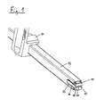
- FIG. 1 shows the possible integration of a controller 10 in an articulated arm awning is shown, of which for illustration only a support tube designed as a square tube 12 and a support bracket 14 for mounting the awning on one Wall or a ceiling projection is shown.
- the control 10 is in the inner cross section of the support tube 12 arranged in cross section adapted control housing 16, which can be inserted laterally into the support tube 12.
- On the front of the housing are three connection options provided, with a first connection 18 for connection to one or more sensors, a second connection 20 for Connection with an electric drive for the folding arm awning and a third connector 22 for connection to one Power supply network, for example a household power network, is provided.
- a side slot 24 allows the lateral execution of those connected to the controller 10 Connection lines to the sensor, the drive and the power supply.
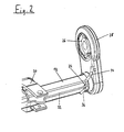
- the support tube 12 is after placing a side Cloth shaft bracket 26 with a side plastic cover 28 shown.
- the bracket 30 of an articulated arm (see Fig. 4 and 5) is attached to the support tube 12 and screwed (Screws not shown).
- After touchdown the cloth shaft bracket 26 and the plastic cap 28 is that Housing 16 invisibly hidden inside the support tube 12.
- Only the connecting cables of the Controller 10, with a sensor line 32 on the support tube 12 is guided along to the articulated arm 30.
- a drive line 34 leads to that in the cloth shaft (not shown) which in the Cloth shaft console 26 can be used, arranged electrical Drive motor (also not shown).
- a supply line 36 will be sent to the nearest distributor connected to the household electricity network. Because the sensor that Drive and control are already wired ready for operation and configured, the articulated arm awning can be Assembly and connecting the supply line 36 with the Household electricity network can be put into operation immediately.
- Fig. 3 is an alternative placement of a controller 110 shown on a support tube 112 of an articulated arm awning, in which the housing 116 of the controller 110 is limited Space cannot be installed. There are therefore mounting brackets 124 provided the support tube Wrap 112 and in grooves provided in the housing 116 125 intervene. At the front of the controller 110 are again Connections 118, 120, 122 for the electrical lines intended. A support tube bracket 114 and a cloth shaft bracket 126 are also shown.
- the controller leading electrical cables can be used in the usual way Help of known fastening aids from the field of electrical installation, z. B. with the help of self-adhesive cable tie loops, be made.
- an articulated arm half 38 is shown with Using a drop joint 40 on a drop profile (not shown) and via a central joint (not shown) on one upper articulated arm is pivotally fixed, the upper articulated arm halves with the articulated arm holder 30 (see FIG. 2) is articulated. Near the joint 40 is a Vibration sensor 42 is provided which through a bore 44 in Profile of the lower articulated arm half 38 into the articulated arm interior can be introduced. The sensor 42 is via the connecting line 32 (see also Fig. 2), which leads past the articulated arm profiles on the outside is connected to the controller 10.
- a cover strip 46 protects the connecting line 32 and the sensor 42 Damage, the cover strip 46 on its long sides has locking lugs 48 which in corresponding grooves 50 engage in the longitudinal direction on the articulated arm half 38 are provided.
- the location of the sensor 42 nearby the failure profile has proven to be advantageous because in particularly strong vibrations and accelerations in this area can occur under the influence of wind load.
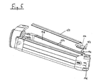
- an installation situation according to 5 may be provided.
- a wind load sensor Vibration sensor 142 protected by a plastic receptacle 144 near the articulated arm center joint 146 on the upper articulated arm half 148 attached.
- It's another one Cover bar 150 is provided, which is not shown in FIG. 5 Connection line to the controller 10 covers.
- the Sensor 142 is installed in plastic receptacle 144 indented and the latter is with retaining tabs 152 in grooves 154 engaged on the upper half of the articulated arm 148, in which the cover strip 150 is also attached.
- the advantage of this Arrangement is that with the connecting line to Control only one joint must be bridged, too the sensor position due to the pronounced movement of the middle joint Also particularly suitable in the event of a wind attack on the cloth is.
- a wire is also preferably in the connecting line 32 integrated as a receiving antenna for a radio remote control the sun protection system can be used.
Landscapes
- Engineering & Computer Science (AREA)
- Architecture (AREA)
- Structural Engineering (AREA)
- Civil Engineering (AREA)
- Blinds (AREA)
- Building Awnings And Sunshades (AREA)
- Wind Motors (AREA)
- Transmission And Conversion Of Sensor Element Output (AREA)
- Train Traffic Observation, Control, And Security (AREA)
- Power-Operated Mechanisms For Wings (AREA)
- Operating, Guiding And Securing Of Roll- Type Closing Members (AREA)
Description
- Fig. 1
- Eine Schrägansicht eines Tragrohrs einer Gelenkarmmarkise;
- Fig. 2
- das Tragrohr gemäß Fig. 1 mit angebrachter Tuchwellenkonsole;
- Fig. 3
- eine alternative Anordnung des Steuerungsgehäuses an dem Tragrohr;
- Fig. 4
- eine schematische Ansicht der Anordnung eines Sensors in einer Gelenkarmhälfte;
- Fig. 5
- eine schematische Ansicht eines Gelenkarmes einer Markise mit außenseitig montiertem Sensor.
Claims (8)
- Sonnenschutzanlage mit einem Sonnenschutzbehang und wenigstens einem elektrischen Antrieb, der mit Hilfe einer Steuerung die Einstellung des Sonnenschutzbehangs in Abhängigkeit von Eingangsgrößen selbsttätig anpaßt, wobei wenigstens ein Sensor (42; 142) zur Erfassung der auf die Sonnenschutzanlage wirkenden Windlast als Eingangsgröße für die Steuerung (10) vorgesehen und die Steuerung betriebsfertig verdrahtet in die Sonnenschutzanlage integriert sind und ein Versorgungsanschluß (36) vorzugsweise zur Verbindung mit einem üblichen Haushaltsstromnetz vorgesehen ist, dadurch gekennzeichnet, daß der Windlastsensor (42; 142) in Form eines Vibrationssensors oder Beschleunigungssensors an einem vom angreifenden Wind stark erregten Bauteil (38; 148) angeordnet ist.
- Sonnenschutzanlage nach Anspruch 1, dadurch gekennzeichnet, daß die Steuerung (10) in einem Gehäuse der Anlage eingebaut oder in einem separaten Steuerungsgehäuse (16; 116) vorgesehen ist, das an oder in Teilen (12; 112) der Sonnenschutzanlage befestigt ist.
- Sonnenschutzanlage nach Anspruch 2, dadurch gekennzeichnet, daß die Steuerung (10) im Tragrohr (12) einer Gelenkarmmarkise integriert ist.
- Sonnenschutzanlage nach Anspruch 2, dadurch gekennzeichnet, daß das Steuerungsgehäuse (116) am Tragrohr (112) einer Gelenkarmmarkise befestigt ist.
- Sonnenschutzanlage nach Anspruch 4, dadurch gekennzeichnet, daß das Steuerungsgehäuse (116) über eine Clipverbindung (124, 125) am Tragrohr (112) befestigt ist.
- Sonnenschutzanlage nach einem der vorhergehenden Ansprüche, dadurch gekennzeichnet, daß der Windlastsensor (42; 142) an oder in einer Gelenkarmhälfte (38; 148) oder im Bereich des Ausfallprofils der Gelenkarmmarkise angeordnet ist.
- Sonnenschutzanlage nach Anspruch 6, dadurch gekennzeichnet, daß der Windlastsensor (42; 142) an oder in einer Gelenkarmhälfte (38) nahe des Ausfallprofils oder an oder in einer Gelenkarmhälfte (148) nahe des Mittelgelenks (146) des Gelenkarms angeordnet ist.
- Sonnenschutzanlage nach einem der vorhergehenden Ansprüche, dadurch gekennzeichnet, daß in die elektrische Verdrahtung zwischen einem Sensor (42; 142), der Steuerung (10) und/oder dem Antrieb eine Empfangsantenne zum Empfang von Fernbedienungssignalen vorgesehen ist.
Applications Claiming Priority (2)
| Application Number | Priority Date | Filing Date | Title |
|---|---|---|---|
| DE19932731 | 1999-07-14 | ||
| DE19932731A DE19932731A1 (de) | 1999-07-14 | 1999-07-14 | Sonnenschutzanlage mit sich dem Lichteinfall anpassender Behangeinstellung |
Publications (3)
| Publication Number | Publication Date |
|---|---|
| EP1069257A2 EP1069257A2 (de) | 2001-01-17 |
| EP1069257A3 EP1069257A3 (de) | 2003-05-02 |
| EP1069257B1 true EP1069257B1 (de) | 2004-09-29 |
Family
ID=7914629
Family Applications (2)
| Application Number | Title | Priority Date | Filing Date |
|---|---|---|---|
| EP00114832A Expired - Lifetime EP1069257B1 (de) | 1999-07-14 | 2000-07-11 | Sonnenschutzanlage mit Sensorsteuerung |
| EP00114880A Withdrawn EP1069275A3 (de) | 1999-07-14 | 2000-07-12 | Sonnenschutzanlage mit sich dem Lichteinfall anpassender Behangeinstellung |
Family Applications After (1)
| Application Number | Title | Priority Date | Filing Date |
|---|---|---|---|
| EP00114880A Withdrawn EP1069275A3 (de) | 1999-07-14 | 2000-07-12 | Sonnenschutzanlage mit sich dem Lichteinfall anpassender Behangeinstellung |
Country Status (3)
| Country | Link |
|---|---|
| EP (2) | EP1069257B1 (de) |
| AT (1) | ATE278081T1 (de) |
| DE (2) | DE19932731A1 (de) |
Families Citing this family (13)
| Publication number | Priority date | Publication date | Assignee | Title |
|---|---|---|---|---|
| US6484069B2 (en) | 2000-01-31 | 2002-11-19 | Turnils Ab | Awning assembly and control system |
| DE10202830A1 (de) * | 2002-01-24 | 2003-08-14 | Colt Internat Holdings Ag Baar | Vorrichtung zum Verstellen von Lichttechnikelementen |
| DE10204469B4 (de) * | 2002-02-05 | 2004-02-12 | Warema Renkhoff Gmbh | Sonnenschutzanlage mit integriertem Regensensor |
| US7111952B2 (en) * | 2003-03-24 | 2006-09-26 | Lutron Electronics Co., Inc. | System to control daylight and artificial illumination and sun glare in a space |
| US7242162B2 (en) * | 2004-11-22 | 2007-07-10 | Carefree/Scott Fetzer Company | Apparatus and method for retracting awning |
| MXPA05012908A (es) | 2004-11-29 | 2006-05-31 | Dometic Corp | Control de toldo con deteccion de viento, que tiene sensor montado en brazo. |
| FR2884607B1 (fr) | 2005-04-13 | 2007-07-13 | Somfy Sas | Capteur domotique autonome et installation comprenant un tel capteur |
| DE102006005408B4 (de) | 2006-02-03 | 2008-04-03 | Roma Rolladensysteme Gmbh | Vorrichtung zum Verschatten von Gebäudeöffnungen |
| DE102007029622A1 (de) * | 2007-06-26 | 2009-01-08 | Weinor Dieter Weiermann Gmbh & Co. | Sonnenschutzanlage |
| FR2922585B1 (fr) * | 2007-10-19 | 2012-09-21 | Somfy Sas | Installation de protection solaire equipee d'un capteur de vent |
| ITTV20080004A1 (it) | 2008-01-10 | 2009-07-11 | Nice Spa | Azionamento per avvolgibili con protezione contro vento eccessivo |
| FR2999304B1 (fr) * | 2012-12-11 | 2016-08-26 | Somfy Sas | Procede de fonctionnement d'un dispositif domotique pour la mise en œuvre d'une periode d'inhibition de la detection de crepuscule |
| FR3013859B1 (fr) * | 2013-11-22 | 2017-11-03 | Somfy Sas | Procede de commande d'une installation exposee aux intemperies, et installation domotique associee |
Family Cites Families (14)
| Publication number | Priority date | Publication date | Assignee | Title |
|---|---|---|---|---|
| BE755183R (fr) * | 1969-08-28 | 1971-02-01 | Hueppe Justin | Dispositif de controle pour installation pare-soleil actionnee par un moteur |
| GB1573104A (en) * | 1977-04-28 | 1980-08-13 | Colt Ltd W | Control system for external louvres on a building |
| DE2800968A1 (de) * | 1978-01-11 | 1979-07-12 | Trietex Antriebstechnik Gmbh | Anordnung zur steuerung von sonnenschutzeinrichtungen mit vertikalen lamellen |
| DE3304962C2 (de) * | 1983-02-12 | 1986-04-10 | Willi 4292 Rhede Rademacher | Verdunkelungsvorrichtung |
| DE3640241A1 (de) * | 1986-11-25 | 1988-05-26 | Ind Elektronik Und Feinmechani | Sonnenschutzverfahren und -vorrichtung |
| DE4032221A1 (de) * | 1990-10-11 | 1992-04-16 | Warema Renkhoff Gmbh & Co Kg | Verfahren und vorrichtung zum steuern von raffstores |
| DE4106033A1 (de) * | 1991-02-27 | 1992-09-03 | Warema Renkhoff Gmbh & Co Kg | Steuervorrichtung fuer sonnenschutzanlagen |
| DE4201971A1 (de) * | 1992-01-22 | 1993-08-05 | Wilhelm Rademacher | Verdunkelungsvorrichtung |
| DE9306368U1 (de) * | 1993-04-27 | 1993-07-08 | Rademacher, Wilhelm, 4292 Rhede | Verdunkelungsvorrichtung mit einer Markise, einer Außenjalousie o.dgl. |
| DE4315406C1 (de) * | 1993-05-08 | 1994-11-10 | Wilhelm Dipl Ing Brabender | Vorrichtung zur automatischen Steuerung von Antrieben für insbesondere Rolläden, Jalousien o. dgl. |
| US5663621A (en) * | 1996-01-24 | 1997-09-02 | Popat; Pradeep P. | Autonomous, low-cost, automatic window covering system for daylighting applications |
| DE19630496A1 (de) * | 1996-07-29 | 1998-02-12 | Selve Ernst Gmbh Co Kg | Vorrichtung zur Erfassung von Meßwerten, zur Realisierung von Motorsteuerungen elektromotorischer Antriebe für auf- und abwickelbare Behänge |
| ATE288526T1 (de) * | 1998-05-28 | 2005-02-15 | Hermann-Frank Mueller | Markise mit flexiblen solarmodulen |
| DE20000682U1 (de) * | 2000-01-17 | 2000-03-30 | Helmut Beyers GmbH, 41066 Mönchengladbach | Vorrichtung zur Steuerung der Bewegung einer Beschattungseinrichtung |
-
1999
- 1999-07-14 DE DE19932731A patent/DE19932731A1/de not_active Withdrawn
-
2000
- 2000-07-11 EP EP00114832A patent/EP1069257B1/de not_active Expired - Lifetime
- 2000-07-11 AT AT00114832T patent/ATE278081T1/de not_active IP Right Cessation
- 2000-07-11 DE DE50007964T patent/DE50007964D1/de not_active Expired - Fee Related
- 2000-07-12 EP EP00114880A patent/EP1069275A3/de not_active Withdrawn
Also Published As
| Publication number | Publication date |
|---|---|
| EP1069257A2 (de) | 2001-01-17 |
| DE19932731A1 (de) | 2001-03-22 |
| DE50007964D1 (de) | 2004-11-04 |
| ATE278081T1 (de) | 2004-10-15 |
| EP1069275A3 (de) | 2003-01-22 |
| EP1069257A3 (de) | 2003-05-02 |
| EP1069275A2 (de) | 2001-01-17 |
Similar Documents
| Publication | Publication Date | Title |
|---|---|---|
| EP1069257B1 (de) | Sonnenschutzanlage mit Sensorsteuerung | |
| EP1666291B1 (de) | Fensterrollo mit vereinfachter montage | |
| DE69807438T2 (de) | Universelle befestigungs- und parallelführungsvorrichtung für eine fensterabschirmung | |
| DE29805142U1 (de) | Halterung für einen Innenrückspiegel eines Kraftfahrzeuges | |
| EP2255058B1 (de) | Aufsatz-Rollladenkasten sowie Profilsystem mit einem solchen Aufsatz-Rollladenkasten | |
| CH695107A5 (de) | Baukastensystem zur Erstellung von Tür- oder Fensterantrieben. | |
| EP3483375A1 (de) | Vorrichtung zum zumindest teilweise automatischen betätigen eines türflügels | |
| DE602004013060T2 (de) | Elektrische Verbindungseinrichtung für motorisierte Systeme von Vorhängen, Rollos und Rollladen im Allgemeinen | |
| EP0513794B1 (de) | Gurtkasten für einen Rolladengurt oder ein ähnliches Zugelement | |
| DE202019103794U1 (de) | Abschlussleiste mit Seitenführung | |
| DE19513954C2 (de) | Zusatzrollo | |
| DE69837184T2 (de) | Untersetzungsgetriebe für motorisierte und automatische Markisen, Stores oder dergleichen | |
| DE4312608A1 (de) | Elektronische Jalousieansteuerung zur Steuerung von elektrisch angetriebenen Jalousien, Rolladen, Markisen, Gardinen, Garagentoren und ähnlichen Einrichtungen | |
| DE202007019643U1 (de) | Senkrechtbeschattung | |
| DE69906314T2 (de) | Fenster-abschirmvorrichtung und eine universelle befestigungs- und parallelführungsvorrichtung für eine fenster-abschirmvorrichtung | |
| DE29904106U1 (de) | Steuerungssystem einer Verdunkelungs- und/oder Sicherungsanlage | |
| EP1686232A2 (de) | Lichtschrankenhalterung | |
| DE29621563U1 (de) | Rollo, insbesondere Seitenfensterrollo für Kfz | |
| DE29906522U1 (de) | Bewegungsmelder | |
| CH693883A5 (de) | Elektrische Antriebsvorrichtung fuer Verdunkelungs- oder Beschattungsvorrichtungen. | |
| DE69717953T2 (de) | Befestigungsvorrichtung für Schiebepaneel | |
| DE19809025C2 (de) | Fassadenrollo und Führungsschiene für ein Fassadenrollo | |
| EP2785931A1 (de) | Kassettenmarkise mit verdeckten befestigungskonsolen | |
| DE19544894C1 (de) | Markise mit einem vertikal ausschwenkbaren Arm | |
| EP3604705B1 (de) | Vorrichtung zur begrenzung des stellweges von antrieben |
Legal Events
| Date | Code | Title | Description |
|---|---|---|---|
| PUAI | Public reference made under article 153(3) epc to a published international application that has entered the european phase |
Free format text: ORIGINAL CODE: 0009012 |
|
| AK | Designated contracting states |
Kind code of ref document: A2 Designated state(s): AT BE CH CY DE DK ES FI FR GB GR IE IT LI LU MC NL PT SE |
|
| AX | Request for extension of the european patent |
Free format text: AL;LT;LV;MK;RO;SI |
|
| PUAL | Search report despatched |
Free format text: ORIGINAL CODE: 0009013 |
|
| AK | Designated contracting states |
Designated state(s): AT BE CH CY DE DK ES FI FR GB GR IE IT LI LU MC NL PT SE |
|
| AX | Request for extension of the european patent |
Extension state: AL LT LV MK RO SI |
|
| GRAP | Despatch of communication of intention to grant a patent |
Free format text: ORIGINAL CODE: EPIDOSNIGR1 |
|
| 17P | Request for examination filed |
Effective date: 20031030 |
|
| AKX | Designation fees paid |
Designated state(s): AT CH DE LI |
|
| GRAS | Grant fee paid |
Free format text: ORIGINAL CODE: EPIDOSNIGR3 |
|
| GRAA | (expected) grant |
Free format text: ORIGINAL CODE: 0009210 |
|
| AK | Designated contracting states |
Kind code of ref document: B1 Designated state(s): AT CH DE LI |
|
| REG | Reference to a national code |
Ref country code: CH Ref legal event code: EP |
|
| REG | Reference to a national code |
Ref country code: IE Ref legal event code: FG4D Free format text: GERMAN |
|
| REF | Corresponds to: |
Ref document number: 50007964 Country of ref document: DE Date of ref document: 20041104 Kind code of ref document: P |
|
| REG | Reference to a national code |
Ref country code: CH Ref legal event code: NV Representative=s name: ISLER & PEDRAZZINI AG |
|
| REG | Reference to a national code |
Ref country code: IE Ref legal event code: FD4D |
|
| PLBE | No opposition filed within time limit |
Free format text: ORIGINAL CODE: 0009261 |
|
| STAA | Information on the status of an ep patent application or granted ep patent |
Free format text: STATUS: NO OPPOSITION FILED WITHIN TIME LIMIT |
|
| 26N | No opposition filed |
Effective date: 20050630 |
|
| REG | Reference to a national code |
Ref country code: CH Ref legal event code: PCAR Free format text: ISLER & PEDRAZZINI AG;POSTFACH 1772;8027 ZUERICH (CH) |
|
| PGFP | Annual fee paid to national office [announced via postgrant information from national office to epo] |
Ref country code: CH Payment date: 20090727 Year of fee payment: 10 Ref country code: AT Payment date: 20090723 Year of fee payment: 10 |
|
| PGFP | Annual fee paid to national office [announced via postgrant information from national office to epo] |
Ref country code: DE Payment date: 20090923 Year of fee payment: 10 |
|
| REG | Reference to a national code |
Ref country code: CH Ref legal event code: PL |
|
| PG25 | Lapsed in a contracting state [announced via postgrant information from national office to epo] |
Ref country code: DE Free format text: LAPSE BECAUSE OF NON-PAYMENT OF DUE FEES Effective date: 20110201 Ref country code: CH Free format text: LAPSE BECAUSE OF NON-PAYMENT OF DUE FEES Effective date: 20100731 Ref country code: LI Free format text: LAPSE BECAUSE OF NON-PAYMENT OF DUE FEES Effective date: 20100731 |
|
| REG | Reference to a national code |
Ref country code: DE Ref legal event code: R119 Ref document number: 50007964 Country of ref document: DE Effective date: 20110201 |
|
| PG25 | Lapsed in a contracting state [announced via postgrant information from national office to epo] |
Ref country code: AT Free format text: LAPSE BECAUSE OF NON-PAYMENT OF DUE FEES Effective date: 20100711 |