EP1069191B1 - Appareil et procédé de coulée - Google Patents
Appareil et procédé de coulée Download PDFInfo
- Publication number
- EP1069191B1 EP1069191B1 EP20000113436 EP00113436A EP1069191B1 EP 1069191 B1 EP1069191 B1 EP 1069191B1 EP 20000113436 EP20000113436 EP 20000113436 EP 00113436 A EP00113436 A EP 00113436A EP 1069191 B1 EP1069191 B1 EP 1069191B1
- Authority
- EP
- European Patent Office
- Prior art keywords
- lance
- tap hole
- tapping
- hole
- sleeve
- Prior art date
- Legal status (The legal status is an assumption and is not a legal conclusion. Google has not performed a legal analysis and makes no representation as to the accuracy of the status listed.)
- Expired - Lifetime
Links
- 238000010079 rubber tapping Methods 0.000 title claims description 84
- 238000000034 method Methods 0.000 title claims description 14
- 238000002844 melting Methods 0.000 claims description 30
- 230000008018 melting Effects 0.000 claims description 30
- 238000001816 cooling Methods 0.000 claims description 27
- 239000000155 melt Substances 0.000 claims description 22
- 239000000463 material Substances 0.000 claims description 13
- 239000000498 cooling water Substances 0.000 claims description 11
- 150000001875 compounds Chemical class 0.000 claims description 10
- RYGMFSIKBFXOCR-UHFFFAOYSA-N Copper Chemical compound [Cu] RYGMFSIKBFXOCR-UHFFFAOYSA-N 0.000 claims description 8
- 229910052802 copper Inorganic materials 0.000 claims description 8
- 239000010949 copper Substances 0.000 claims description 8
- 229910000881 Cu alloy Inorganic materials 0.000 claims description 6
- 238000004056 waste incineration Methods 0.000 claims description 6
- 238000002485 combustion reaction Methods 0.000 claims description 4
- XLYOFNOQVPJJNP-UHFFFAOYSA-N water Substances O XLYOFNOQVPJJNP-UHFFFAOYSA-N 0.000 claims description 4
- 230000008878 coupling Effects 0.000 description 12
- 238000010168 coupling process Methods 0.000 description 12
- 238000005859 coupling reaction Methods 0.000 description 12
- 230000033001 locomotion Effects 0.000 description 10
- 239000000969 carrier Substances 0.000 description 5
- 230000000694 effects Effects 0.000 description 3
- 239000007789 gas Substances 0.000 description 3
- 238000003780 insertion Methods 0.000 description 3
- 230000037431 insertion Effects 0.000 description 3
- 238000003723 Smelting Methods 0.000 description 2
- 238000011161 development Methods 0.000 description 2
- 230000018109 developmental process Effects 0.000 description 2
- 230000000630 rising effect Effects 0.000 description 2
- 239000002023 wood Substances 0.000 description 2
- 238000004140 cleaning Methods 0.000 description 1
- 239000004020 conductor Substances 0.000 description 1
- 238000010276 construction Methods 0.000 description 1
- 230000007423 decrease Effects 0.000 description 1
- 230000001419 dependent effect Effects 0.000 description 1
- 230000002996 emotional effect Effects 0.000 description 1
- 230000007613 environmental effect Effects 0.000 description 1
- 238000001914 filtration Methods 0.000 description 1
- 230000017525 heat dissipation Effects 0.000 description 1
- 230000002706 hydrostatic effect Effects 0.000 description 1
- 230000010354 integration Effects 0.000 description 1
- 239000002184 metal Substances 0.000 description 1
- 229910052751 metal Inorganic materials 0.000 description 1
- 230000002028 premature Effects 0.000 description 1
- 239000011819 refractory material Substances 0.000 description 1
- 238000007789 sealing Methods 0.000 description 1
- 230000035939 shock Effects 0.000 description 1
- 239000007787 solid Substances 0.000 description 1
- 238000007711 solidification Methods 0.000 description 1
- 230000008023 solidification Effects 0.000 description 1
- 238000009827 uniform distribution Methods 0.000 description 1
Images


Classifications
-
- C—CHEMISTRY; METALLURGY
- C21—METALLURGY OF IRON
- C21B—MANUFACTURE OF IRON OR STEEL
- C21B7/00—Blast furnaces
- C21B7/12—Opening or sealing the tap holes
-
- F—MECHANICAL ENGINEERING; LIGHTING; HEATING; WEAPONS; BLASTING
- F27—FURNACES; KILNS; OVENS; RETORTS
- F27D—DETAILS OR ACCESSORIES OF FURNACES, KILNS, OVENS OR RETORTS, IN SO FAR AS THEY ARE OF KINDS OCCURRING IN MORE THAN ONE KIND OF FURNACE
- F27D3/00—Charging; Discharging; Manipulation of charge
- F27D3/15—Tapping equipment; Equipment for removing or retaining slag
- F27D3/1509—Tapping equipment
- F27D3/1536—Devices for plugging tap holes, e.g. plugs stoppers
Definitions
- the invention relates to a tapping device for a Melting furnace according to the preamble of claim 1 and a lance for closing and opening the tap hole a melting furnace. Furthermore, the invention relates to a Tapping method for a melting furnace according to The preamble of claim 14.
- a generic tapping device with a filling device for filling the open tap hole with a stuffing and with a moveable stuffing device for inserting a lance into the tapping opening known.
- the lance a simple one elongated rod, is doing under shock and Shaking movements introduced into the tap hole after the stuffing mass has been filled, e.g. with help of a Hammer, and remains there until reopening the tap hole by pulling the lance.
- DE 3 803 132 A1 discloses a tapping device known, in the closing of the taphole a Stuffed mass and at the same time one to the Tapping the stove in the tap hole remaining lance in the Stuffing compound is introduced.
- the tapping device a stuffing head with a through hole through which both the stuffing mass and the lance is inserted into the tapping opening.
- FR 2 680 179 describes a tapping device in which a lance is used Finds which channels has the introduction of gases into the blast furnace should serve. Water as a means for cooling is not described.
- DD 278 721 discloses a method and a device for closing the Tapping opening in a hut stove, in particular on a cupola.
- the Lance which is used in this process, is cooled.
- the open tap hole is initially using the Filling device filled with stuffing material.
- the stuffing device carries the lance in the tap hole.
- the lance be introduced simultaneously with the stuffing. In both cases will be part of the tapping opening Stuffing mass from the lance further into the Tapping opening pressed.
- Heat hardens the stuffing material.
- the in the tap hole introduced lance is mechanically secured from the outside. To open the tap hole the lance is pulled. It is characterized by that of the located in the furnace Melt caused hydrostatic pressure which is still in the tapping opening stuffing mass from the tap hole pressed so that the melt unhindered out of the Melting furnace can drain through the tap hole.
- the wall thickness can be from conventional 600-800 mm to about Half to one third be reduced.
- melting furnaces constructible in particular for melting the Combustion residues in waste incineration plants are suitable.
- the lance is preferably made of copper or made of a copper alloy and with at least one Cooling channel provided to a cooling water supply can be connected.
- the Stopfkopf and / or the area around the tap hole cooled. This further improves the cooling effect.
- the stuffing device is before the Tapping of the melting furnace one preferably Copper or similar thermally conductive material manufactured front panel with an outlet opening arranged, which leaves the tapping opening.
- the stuffing device is when inserting the Lance in the tap hole preferably a form-fitting the plate attachable, as a sealing element between the stuffing device and the tapping opening acts.
- this plate also coolable, e.g. by means of water cooling.
- the Stopfkopf in addition to a supply channel on, in the through hole of the stuffing head opens.
- the Supply channel is connected to the filling device, the required for closing the tap hole Stuffing material through the supply channel and the Through hole in the taphole promotes.
- the then introduced through the through hole Lance pushes the still in the through hole and in the Tapping hole included stuffing in their final Location in the tap hole, creating a uniform Distribution of stuffing around the lance in the Tap opening is guaranteed.
- a wooden plug in the Tapping opening is introduced.
- This is for example is arranged in the through hole of the stuffing head and is due to the pressure of the stuffing mass, if necessary supported by the pressure of the lance, in the Tapping opening conveyed, pushed through this, pushed into the melt and burned. In this way prevents the cooling of the lance and the Stopfkopfes or the front plate the melt locally so is cooled far, that metal plates in the Form tapping opening.
- the lance on a sleeve which at its the Tapping opening facing the end is placed.
- the sleeve consists of a material that is the same or a has lower melting point than that in the furnace contained melt, preferably made of copper or a Copper alloy.
- the sleeve has the advantage that pulling the lance is simplified because its contact surface with the stuffing material is reduced. The lance is therefore less damaged and can be reused.
- the sleeve is a Wearing.
- Stopfkopfes To insert the lance through the through hole of the Stopfkopfes serves a feed unit.
- the Stopfkopfes By the Using the Stopfkopfes the taphole during the insertion of the lance to the outside at least partially sealed. At the same time, it ensures in the stuffing head Trained through hole that lance in one defined insertion in the tap hole is introduced so that any damage to the refractory material in the tapping opening be avoided.
- a feed unit for the stuffing device is suitable in particular a hammer drill or a hydraulic Drive.
- a hammer drill can in addition to the Feed movement of the lance at the same time a rotational Movement of the lance about its longitudinal axis and a Shaking generated in the direction of its longitudinal axis become.
- the combined rotation and Shaking movement is distributed in the tap hole Stuffing mass contained particularly uniform around the itself in the tapping opening moving lance, while simultaneously counter to the feed movement of the lance acting forces are lower than a lance, the exclusively with an axial movement in the Tapping opening is introduced.
- the Rotation also be waived.
- the tapping is a fully automatic opening and closing the tap opening allows, so that the Tapping opening and the pouring trough of the melting furnace together with the functional units of the tapping device in a closed to the outside housing can be accommodated in which the melt collected rising gases and suspended matter and one Cleaning and filtering system can be supplied.
- This is especially when using the tapping device for a smelting furnace of a mill incineration plant of Advantage in which the resulting gases and rising Suspended solids for environmental reasons as completely as possible be caught and neutralized or filtered out have to.
- a pull-out device is suitable, for example a movable in the longitudinal direction of the tapping opening Holder which can be coupled to the lance.
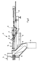
- Figs. 1 to 4 show partially cut Side views of a tapping 10 in different Operating positions when opening and closing a tapping opening 12 of a furnace 14 of a waste incineration plant.
- the tapping device 10 has two approximately parallel to the longitudinal direction of the tap opening 12 extending in the Cross-section U-shaped support 16, which at a distance to each other and from those in Figs. 1 to 4 For clarity, only the background arranged carrier 16 is shown.
- the carriers 16 are on a hopper 18 provided on the furnace 14 fixed, which is arranged below the tap opening 12 and by the emerging from the tapping opening 12 Melt, for example, in a mold 20 (see Fig. 2) can be steered. With her the hopper 18th remote from the end portions are the two carriers 16 a transverse to this first I-beam 22, to which they are attached.
- a second I-beam 24 is arranged, the between the two supports 16 extends transversely to these and is firmly connected with these. Furthermore, at each Carrier 16 a longitudinal beam 26 attached, which in cross section L-shaped. Again, for the sake of Clarity in Figs. 1 to 4 only in the Background arranged side rails 26 can be seen.
- the Side members 26 are attached to the supports 16, that their horizontally extending legs facing each other are and arranged with the above, also horizontal extending legs of the U-shaped support 16, the facing away from each other, a cross-sectionally U-shaped Form leadership.
- a carriage 28 In the guide a carriage 28 is guided through two pairs of rollers 30 and 32 on top of the horizontally extending legs of the two carriers 16 unrolls. Near the one shown in Figs. 1 to 4 right Roller pair 32, a connection element 34 is provided, the firmly connected to the piston of a hydraulic cylinder 36 is.
- the hydraulic cylinder 36 is with its in Figs. 1 to 4 left end shown on a pivot receptacle 38th pivotally mounted, the center between the supports 16 am second I-beam 24 is attached.
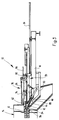
- Stopfkopf 40 in which several Cooling channels (not shown) are formed, the a cooling water supply are connected.
- Stopfkopf 40 is a longitudinal direction of the carriage 28th extending through bore 42 formed in the one at an angle to the through hole 42 extending Supply channel 44 opens.
- Supply channel 44 In the supply channel 44 is the free end of a delivery cylinder 46 used in the a piston 48 slidably mounted and with the help of a hydraulic cylinder 50 is movable.
- the stuffing head 40 is divided along the through hole 42, is with Help of two locks (not shown) held together and may become one later explanatory purpose to be opened.
- the carrier element 52 has a sliding bearing 54, its axis of symmetry with the axis of symmetry of the Through hole 42 of Stopfkopfes 40 coincides.
- a linkage 56 of a Drill hammer 58 of a feed unit 60 rotatable and slidably mounted.
- the hammer mill 58 of the Feed unit 60 is attached to a slider 62, the with the help of two sides of the hammer drill 58th arranged, pneumatic feed cylinder 64 in the longitudinal direction of the carriage 28 between a starting position near the end of the illustrated in Figs. 1 to 4 right Wagens 28, and an end position is movable, in which the Slider 62 is disposed near the sliding bearing 54. Also here is for clarity only in the Background shown feed cylinder 64 shown.
- a coupling head 66 is attached at the free end of the linkage 56, in Figs. 1 to 4 left shown. With the Coupling head 66 is a coupling end 68 of a first Lance 70 coupled, the other end partially in the Through hole 42 of Stopfkopfes 40 protrudes.
- the first Lance 70 has a cooling channel through Connections 72 near the coupling end 68 to a Cooling water supply can be connected. Further is on the carriage 28 extending in the longitudinal direction thereof Coupling hook 74 pivotally mounted, whose purpose later will be explained.
- Extractor 76 includes a support 16 fixed frame 78 with an approximately parallel to Direction of movement of the carriage 28 along the carriers 16 extending guide rail 80.
- a holder 82 slidably held around the Guide bar 80 between a holding position in which the Holder 82 is aligned with the tapping opening 12, and a release position are pivoted, in which the Bracket 82 is pivoted away from the carrier 16 to the rear.
- the Holder 82 in which the Holder 82 is pivoted to its holding position is on the holder 82 is identical to the first lance 70 trained second lance 84 coupled in the Tapping 12 of the furnace 14 is inserted and the Tapping opening 12 closes.
- the second lance 84 to the cooling water supply (not shown) connected.
- On the bracket 82 is also a parallel to the guide rail 80 projecting dog hook 86th provided to the coupling hook 74 of the carriage 28th is aligned when the holder 82 in their in Fig. 1 shown holding position is pivoted.
- the Strahlumschplatte 88 has at its near the Tapping opening 12 arranged approximately vertically extending End of an opening 90, whose diameter is so dimensioned is that the Stopfkopf 40 with its frustoconical designed investment area through the opening 90th can protrude through.
- a round plate 94th attached, which is extended with a cone-shaped Outlet opening 96 is provided, which concentric to Tapping opening 12 of the furnace 14 is arranged.
- the both lances 70 and 84 is also the plate 94 with Cooling channels (not shown) provided to the Cooling water supply are connected.
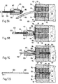
- the Stopfkopf 40 can also 180 ° around the horizontal be rotated, with all machine parts above the Stopfkopfes are arranged and the stuffing material from above is supplied as shown in Fig. 5A-D. This has the Advantage that the exiting melt stream no parts damage the stuffing device and on the Strahlumlenkplatte can be waived.
- the carriage 28 is in his Starting position in which the piston of the hydraulic cylinder 36 retracted while the rear roller pair 32 close the pivot receptacle 38 is arranged. simultaneously closes the inserted into the tapping opening 12 Lance 84, the tap opening 12 and prevents the Leakage of melt from the oven 14. This serves the Extractor 76 coupled to second lance 84 as fixation for the lance 84.
- the tapping 10 for the closing of the tap opening 12th Before opening the tap opening 12 is the tapping 10 for the closing of the tap opening 12th prepared.
- the hopper 18 With a fast-curing stuffing material filled.
- the cooling water supply to the coupled to the feed unit 60 first lance 70 connected and the first lance 70th cooled.
- the tapping opening 12 of the furnace 14 is opened be, first with the help of the hydraulic cylinder 36th the carriage 28 in the direction of the tap opening 12 so far moves until the coupling hook 74 with the driving hook 86 of the puller 76 comes into engagement. Subsequently, the carriage 28 through the hydraulic cylinder 36 moved back to its original position, wherein the engaging with the catch hook 86 Coupling hook 74, the holder 82 along the Guide strip 80 moves. This will be the to the Bracket 82 coupled second lance 84 from the Tapping opening 12 is pulled, as shown in Fig. 2. Simultaneously with the movement of the carriage 28 moves the Actuator the Strahlumschplatte 88 of the tap hole 12 away and releases the hopper 18. Under the Hopper 18 has been the mold 20 in the meantime positioned in the from the tapping opening 12th escaping melt flows.
- the tapping opening 12 is closed, is the carriage 28 together with the Strahlumlenkplatte 88 the tapping opening 12 to move. It stands out frustoconical head portion of Stopfkopfes 40 through the opening 90 of the Strahlumlenkplatte 88th
- the Hydraulic cylinder 36 is extended until the Stuffing head 40 with its frustoconical head section at least partially in the conical exit opening 96 of the plate 94 is received, as in Fig. 3rd shown.
- the hydraulic cylinder 50 of the delivery cylinder 46 is turned on by the Piston 48 in the direction of the through hole 42nd emotional. In this case, the containing in the delivery cylinder 46 Stuffing mass through the supply channel 44 and you Through hole 42 pressed into the tap hole 12, as shown in Fig. 3.
- the hammer drill 58 of the feed unit 60 is turned on and the Feed cylinder 64 of the feed unit 60 under pressure set.
- the feed cylinder 64 is the Hammer drill 58 of the slider 52 in the direction of Tapping opening 12 moves, wherein the first lance 70th continuously with even rotation and shaking Movements in the tapping opening 12 is introduced.
- the stuffing contained in the tapping opening 12 evenly on the inner wall of the tapping opening 12th distributed so that the first lance 70 evenly into the embedded in the tapping 12 stuffing embedded is.
- the carriage 28 is over a predetermined period of for example 15 minutes until the fast curing stuffing cured in the tap hole 12 is.
- the second lance 84 from the bracket 82 of the extractor 76 dissolved and the bracket 82nd coupled to the coupling end 86 of the first lance 70.
- the second lance 84 may, if still reusable is, in the meantime cleaned Stopfkopf 40th inserted and with the coupling head 66 of the hammer drill 58 are verkuppelt.
- the carriage 28 is back to its original position moved back so that the tapping 10 again in their starting position shown in Fig. 1 located.
- Stopfkopf 40 used, on which the delivery cylinder 86th is attached.
- Supply channel 44 of Stopfkopfes 40 a supply line through, for example, with the help a volumetrically effective pump the Stopfkopf 40th Stuffing mass can be supplied.
- One Melting furnace 108 contains in its by a wall 111 and 112 bounded inside a melt 110.
- the melt 110 flows through a tap hole 113 in the wall 112 as a melt jet 109 from the furnace 108.
- the Melting furnace 108 has in the region of the tap hole 113th a preferably cooled front panel 114.
- a wood plug 115 is arranged, the first to prevent premature Solidification of the melt in the tap hole 113th is introduced, Fig. 5B. Then the by the Stopfkopf 101 supplied stuffing 107 into the tap hole 113 pressed. A lance 102 is replaced by a continuous longitudinal bore in the housing 105 of the stuffing head 101 tracked into the tap opening 1113, Fig. 5C.
- the Lance 102 is made of an elongated preferably cooled lance body 103, on the front end 103 'one at its end facing the furnace closed Sleeve 104 is attached.
- the lance 103 is the Stuffing 107 and the wood plug 115 partially up in the melt 110 is pressed in. The wooden plug 115 then burns in the melt 110.
- the lance 103 extends in the inserted state over the entire Length of the tap hole 113, preferably protruding front tip of the sleeve 104 into the melt 110. Um to keep the oven closed, the lance 103 mechanically secured.
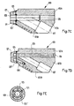
- FIG. 6 shows a partially sectioned side view a lance 116 with an elongated lance body 137.
- the lance main body 137 has a cooling channel 119 on, substantially along the longitudinal axis of the lance 116 runs over about 2/3 of the total length of the Lance extends.
- a cooling circuit are two ports 117, 118 for the supply and discharge provided by cooling water.
- the length of the lance is preferably 180-250 cm. Their diameter is preferably 30-50 mm.
- FIGs. 7A-E are various views of one Stopfkopfes 120 shown.
- Figures 7A and 7B show the Stopfkopf in view from above or from the side.
- characters Figs. 7C, 7D and 7E show sections along the lines J-K (Fig. 7C), G-H (Fig. 7D) and A-B (Fig. 7E).
- the Stopfkopf 120 is on two rails 123, 124 to a Not shown here tap hole of a melting furnace approachable, so that its front plate 121 form-fitting closes with the wall of the oven.
- the case of the Stopfkopfes 120 has a continuous longitudinal bore 128, 129 for pushing in and pushing through a lance.
- One Supply channel 127 for stuffing material opens in the furnace side Area of the longitudinal bore 128 in the through hole 129th the front plate 121.
- Cooling channels 125, 125 'arranged for cooling the Stopfkopfes 120, in particular its the melt stream exposed front plate 121, to a cooling circuit can be connected (connection 126).
- Figures 8A and 8B show the front plate 130 of a melting furnace in a partially sectioned view from the front (Fig. 8A) or in cross section along the line C-D.
- the front plate 130 has a round center hole 131 on, concentric with the tap hole of a furnace is arranged. To the center hole 131 extends Cooling passage 133, via terminals 134, 135 to a Cooling circuit can be connected.
- the cooling channel 133 is by notches in the flat body 132 of the Front panel 130 formed with an annular Disc 136 are covered.
Landscapes
- Engineering & Computer Science (AREA)
- Chemical & Material Sciences (AREA)
- Mechanical Engineering (AREA)
- Materials Engineering (AREA)
- Metallurgy (AREA)
- Organic Chemistry (AREA)
- Manufacturing & Machinery (AREA)
- General Engineering & Computer Science (AREA)
- Furnace Charging Or Discharging (AREA)
- Gasification And Melting Of Waste (AREA)
- Processing Of Solid Wastes (AREA)
- Carbon Steel Or Casting Steel Manufacturing (AREA)
- Vertical, Hearth, Or Arc Furnaces (AREA)
Claims (16)
- Dispositif de coulée pour un four de fusion, pour faire fondre des résidus de combustion, près ou dans une centrale d'incinération des ordures ménagères, avec un système de remplissage déplaçable (46) pour remplir un trou de coulée ouvert (12, 113) sur le four de fusion (14, 108), avec une masse de bourrage (107) et avec un système de coulée déplaçable (40), pour l'introduction d'une lance (70, 84, 102, 116) dans le trou de coulée (12, 113), le système de coulée comportant une tête de coulée (40, 101, 120) dans laquelle est ménagé un alésage traversant (42, 129) pour l'introduction de la lance (70, 84, 102, 116) dans le trou de coulée (12, 113), caractérisé en ce que la lance (70, 84, 102, 116) comporte des moyens de refroidissement à l'eau.
- Dispositif de coulée selon la revendication 1, caractérisé en ce que la lance (70, 84, 102, 116) est une lance fabriquée de préférence en cuivre ou dans un alliage de cuivre (70, 84, 102, 137) avec au moins un canal de refroidissement (119) qui peut être raccordé sur une alimentation d'eau de refroidissement.
- Dispositif de coulée selon l'une quelconque des revendications précédentes, caractérisé par un panneau frontal (94, 114, 130), fabriqué de préférence en cuivre avec un orifice de sortie (96, 131), qui par son orifice de sortie (96, 131) peut être fixé de façon concentrique par rapport au trou de coulée (12, 113) sur le four de fusion (14, 108) et sur lequel le système de coulée (40) peut être appliqué lors de l'introduction de la lance (70, 84, 102, 116) dans le trou de coulée (12, 113).
- Dispositif de coulée selon la revendication 3, caractérisé en ce que le panneau frontal (94, 114, 130) peut être refroidi, de préférence, en ce qu'il comporte au moins un canal de refroidissement (133) qui peut être raccordé sur une alimentation d'eau de refroidissement.
- Dispositif de coulée selon l'une quelconque des revendications précédentes, caractérisé en ce que la tête de coulée (49, 101, 120) peut être refroidie, de préférence en ce qu'elle comporte au moins un canal de refroidissement (125, 125'), qui peut être raccordé sur une alimentation d'eau de refroidissement.
- Dispositif de coulée selon l'une quelconque des revendications précédentes, caractérisé en ce qu'un canal d'alimentation (44, 127) débouchant dans l'alésage traversant (42, 129), qui pour l'introduction de la masse de bourrage (107) dans l'alésage traversant (42, 129) est relié avec le dispositif de remplissage (46), de façon à ce que pour le remplissage du trou de coulée (12, 113), la masse de bourrage (107) arrive à travers le canal d'alimentation (44, 127) et à travers l'alésage traversant (42, 129) dans le trou de coulée (12, 113) est ménagé dans la tête de coulée (40, 101, 120).
- Dispositif de coulée selon la revendication 6, caractérisé en ce qu'avant le remplissage du trou de coulée (12, 113,), on ferme l'alésage traversant (42, 129) avec un bouchon de bois (115), qui lors du remplissage de la masse de bourrage (107) est poussé dans le trou de coulée (12, 113).
- Dispositif de coulée selon l'une quelconque des revendications précédentes, caractérisé en ce que la lance (70, 84, 102, 116) comporte une douille (104) qui est posée par son extrémité dirigée vers le trou de coulée (12, 113) et qui est composée d'une matière avec un point de fusion inférieur à celui de la masse en fusion (110) contenue dans le four de fusion (14, 108), de préférence de cuivre ou d'un alliage de cuivre.
- Dispositif de coulée selon la revendication 7, caractérisé en ce que le frottement entre la lance (70, 84, 102, 116) et la douille (104) est tel que lors du retrait de la lance (70, 84, 102, 116), la douille (104) reste dans le trou de coulée (12, 113).
- Lance (70, 84, 102, 116) pour fermer et pour ouvrir le trou de coulée (12, 113) d'un four de fusion (14, 108), pour faire fondre des résidus de combustion près de ou dans une centrale d'incinération d'ordures ménagères, caractérisée en ce que la lance (70, 84, 102, 116) comporte au moins un canal de refroidissement (119) qui peut être raccordé sur une alimentation d'eau de refroidissement.
- Lance (70, 84, 102, 116) selon la revendication 10, caractérisée en ce que la lance (70, 84, 102, 116) comporte une douille (104) qui est posée par son extrémité (103') dirigée vers le trou de coulée (12, 113) et qui est composée d'une matière avec un point de fusion inférieur à celui de la masse en fusion (110) contenue dans le four de fusion (14, 108), de préférence de cuivre ou d'un alliage de cuivre.
- Lance (70, 84, 102, 116) selon la revendication 11, caractérisée en ce que le frottement entre la lance (70, 84, 102, 116) et la douille (104) est tel que lors du retrait de la lance (70, 84, 102, 116), la douille (104) reste dans le trou de coulée (12, 113).
- Procédé de coulée pour un four de fusion (14, 108) pour faire fondre des résidus de combustion près de ou dans une centrale d'incinération d'ordures ménagères, dans lequel pour fermer un trou de coulée (12, 113) ouvert sur le four de fusion (14, 108), on met à disposition une masse de bourrage (107) et une lance (70, 84, 102, 116), on remplit le trou de coulée (12, 113) ouvert au moins partiellement avec la masse de bourrage (107) et simultanément ou par la suite, on introduit la lance (70, 84, 102, 116) dans le trou de coulée (12, 113), caractérisé en ce que la lance (70, 84, 102, 116) est refroidie à l'eau.
- Procédé de coulée selon la revendication 13, dans lequel la lance (70,84, 102, 116) pousse au moins partiellement la masse de bourrage dans le trou de coulée (12, 113) lorsqu'elle est introduite dans le trou de coulée (12, 113).
- Procédé de coulée selon la revendication 13 ou 14, dans lequel on met à disposition un bouchon de bois (115) qui est introduit par la masse de bourrage (107) dans le trou de coulée (12, 13) et qui est poussé à travers ce dernier, de préférence en étant poussé par la masse de bourrage (107.
- Procédé selon la revendication 13, 14 ou 15, dans lequel sur l'extrémité (103') de la lance 70, 84, 102, 116) qui est dirigée vers le trou de coulée (12, 113) on pose une douille (104), qui est composée d'une matière avec un point de fusion inférieur à celui de la masse en fusion (110) contenue dans le four de fusion (14, 108), de préférence de cuivre ou d'un alliage de cuivre, la lance (70, 84, 102, 116) étant introduite avec la douille (104) dans le trou de coulée 12, 113) et lors du retrait de la lance (70, 84, 102, 116), la douille (104) restant dans le trou de coulée (12, 113).
Applications Claiming Priority (2)
| Application Number | Priority Date | Filing Date | Title |
|---|---|---|---|
| CH124599 | 1999-07-07 | ||
| CH124599 | 1999-07-07 |
Publications (2)
| Publication Number | Publication Date |
|---|---|
| EP1069191A1 EP1069191A1 (fr) | 2001-01-17 |
| EP1069191B1 true EP1069191B1 (fr) | 2005-09-28 |
Family
ID=4205878
Family Applications (1)
| Application Number | Title | Priority Date | Filing Date |
|---|---|---|---|
| EP20000113436 Expired - Lifetime EP1069191B1 (fr) | 1999-07-07 | 2000-06-24 | Appareil et procédé de coulée |
Country Status (3)
| Country | Link |
|---|---|
| EP (1) | EP1069191B1 (fr) |
| JP (1) | JP2001056185A (fr) |
| DE (1) | DE50011237D1 (fr) |
Cited By (1)
| Publication number | Priority date | Publication date | Assignee | Title |
|---|---|---|---|---|
| CN105698541A (zh) * | 2015-12-31 | 2016-06-22 | 遵义伟明铝业有限公司 | 一种熔铝炉出料口的封口装置 |
Families Citing this family (4)
| Publication number | Priority date | Publication date | Assignee | Title |
|---|---|---|---|---|
| ES2197738B1 (es) * | 2001-02-15 | 2005-03-16 | Productos Refractarios Asturianos Para La Siderurgia, S.A. | Sistema para reparar los frontales de piquera en alto horno. |
| JP6521088B2 (ja) | 2015-10-19 | 2019-05-29 | 日本製鉄株式会社 | 熱間鍛造用鋼及び熱間鍛造品 |
| CN112857052A (zh) * | 2021-02-01 | 2021-05-28 | 琪玥环保设备(唐山)有限公司 | 一种堵孔装置及具有其的等离子体炉 |
| JP7684431B2 (ja) * | 2021-05-06 | 2025-05-27 | ティエムティ - タッピング メジャーリング テクノロジー エスエイアールエル | 酸素ランスガイドアセンブリ |
Family Cites Families (9)
| Publication number | Priority date | Publication date | Assignee | Title |
|---|---|---|---|---|
| US2294162A (en) * | 1942-08-25 | Blast furnace cinder notch stopper | ||
| JPS52150703A (en) * | 1976-06-11 | 1977-12-14 | Nippon Steel Corp | Tap hole opening in blast furnace |
| JPS5585609A (en) * | 1978-12-21 | 1980-06-27 | Nippon Steel Corp | Boring method for tap hole of blast furnace |
| JPS5690906A (en) * | 1979-12-24 | 1981-07-23 | Kawasaki Steel Corp | Temperature controlling method of mud for closing iron notch |
| DD258721A3 (de) * | 1986-03-26 | 1988-08-03 | Funk A Bergbau Huettenkombinat | Verfahren und vorrichtung zum schliessen einer abstichoeffnung |
| DE3803132A1 (de) * | 1988-02-03 | 1989-08-17 | Dango & Dienenthal Maschbau | Verfahren und stopfkanone zum schliessen des stichlochs von oefen |
| DD259760A3 (de) * | 1988-06-18 | 1988-09-07 | Funk A Bergbau Huettenkombinat | Einrichtung zum schliessen einer abstichoeffnung |
| FR2680179B1 (fr) * | 1991-08-07 | 1994-10-21 | Boulonnais Terres Refractaires | Perfectionnements apportes aux dispositifs de bouchage de trous de coulee de hauts-fourneaux. |
| LU88453A1 (fr) * | 1994-01-17 | 1995-09-01 | Wurth Paul Sa | Dispositif de bouchage du trou de coulée |
-
2000
- 2000-06-24 DE DE50011237T patent/DE50011237D1/de not_active Expired - Fee Related
- 2000-06-24 EP EP20000113436 patent/EP1069191B1/fr not_active Expired - Lifetime
- 2000-07-07 JP JP2000206591A patent/JP2001056185A/ja active Pending
Cited By (2)
| Publication number | Priority date | Publication date | Assignee | Title |
|---|---|---|---|---|
| CN105698541A (zh) * | 2015-12-31 | 2016-06-22 | 遵义伟明铝业有限公司 | 一种熔铝炉出料口的封口装置 |
| CN105698541B (zh) * | 2015-12-31 | 2018-05-18 | 遵义伟明铝业有限公司 | 一种熔铝炉出料口的封口装置 |
Also Published As
| Publication number | Publication date |
|---|---|
| JP2001056185A (ja) | 2001-02-27 |
| EP1069191A1 (fr) | 2001-01-17 |
| DE50011237D1 (de) | 2005-11-03 |
Similar Documents
| Publication | Publication Date | Title |
|---|---|---|
| DE2630232C2 (de) | Automatische Abstichmaschine für den Abstich bei elektrischen Hochöfen und Öfen für die Herstellung von Legierungen o.dgl. | |
| DE3019811C2 (de) | Abflußsteuerorgan für einen Schmelzofen | |
| WO2000006325A2 (fr) | Systeme de fermeture coulissant pour recipient contenant du metal fondu | |
| DE2912295C2 (de) | Verfahren zur Reparatur des Abstichlochs eines Konverters | |
| EP0819488B1 (fr) | Fermeture à tiroir pour un récipient contenant un bain métallique en fusion | |
| EP1069191B1 (fr) | Appareil et procédé de coulée | |
| EP0727268A2 (fr) | Fermeture à tiroir pour un convertisseur contenant un bain métallique | |
| DE2317663A1 (de) | Vorrichtung zur steuerung des ausflusses der metallschmelze aus einem schmelzgutbehaelter | |
| DE7721078U1 (de) | Giessgeraet | |
| DE3911736C2 (de) | Schließ- und/oder Regelorgan für ein metallurgisches Gefäß | |
| EP0182974A1 (fr) | Procédé et dispositif pour ouvrir et obturer un trou de coulée dans des fours | |
| EP0589238B1 (fr) | Procédé de renouvellement des parois chauffantes d'une batterie de fours à coke | |
| DE3801164C2 (de) | Verfahren zum Einführen von Gas in eine Ausgussöffnung eines Metallschmelze, insbesondere Stahlschmelze enthaltenden Behälters sowie Ausgusshülse zur Durchführung des Verfahrens | |
| DE4492636C2 (de) | Abstichloch und Verfahren zur Bildung eines Abflusskanals eines Abstichlochs | |
| DE9408700U1 (de) | Vorrichtung zum Anschließen und Wechseln eines Gießrohres an ein Metallschmelze enthaltendes Gefäß | |
| EP0974801A1 (fr) | Procédé et dispositif pour laisser couler exempt de scories | |
| EP3399103A1 (fr) | Aiguillage et procédé de fabrication d'un aiguillage | |
| EP3851225A1 (fr) | Fermeture coulissante pour une cuve métallurgique | |
| EP0522284A1 (fr) | Plaque réfractaire pour fermeture à tiroir de poches de coulée | |
| DE2526815A1 (de) | Verfahren zum automatischen entschlacken eines kupolofens | |
| DE2120670A1 (de) | Verfahren und Vorrichtung zum Ausstoßen des Walzstopfens für Walzwerke | |
| DE2821989C2 (de) | Verfahren und Vorrichtung zur Sicherung der Gießeinheit einer Warmkammer-Druckgießmaschine gegen unbeabsichtigtes Auslösen des Gießvorganges | |
| DE524194C (de) | Reversibler, regenerativ beheizter Schmelzofen | |
| EP1577036B1 (fr) | Dispositif de dosage pour matière fondue | |
| WO2005024069A2 (fr) | Dispositif de debouchage destine a une cuve de fusion, en particulier a un convertisseur |
Legal Events
| Date | Code | Title | Description |
|---|---|---|---|
| PUAI | Public reference made under article 153(3) epc to a published international application that has entered the european phase |
Free format text: ORIGINAL CODE: 0009012 |
|
| AK | Designated contracting states |
Kind code of ref document: A1 Designated state(s): CH DE FR LI NL |
|
| AX | Request for extension of the european patent |
Free format text: AL;LT;LV;MK;RO;SI |
|
| 17P | Request for examination filed |
Effective date: 20010210 |
|
| AKX | Designation fees paid |
Free format text: CH DE FR LI NL |
|
| 17Q | First examination report despatched |
Effective date: 20031125 |
|
| GRAP | Despatch of communication of intention to grant a patent |
Free format text: ORIGINAL CODE: EPIDOSNIGR1 |
|
| GRAS | Grant fee paid |
Free format text: ORIGINAL CODE: EPIDOSNIGR3 |
|
| GRAA | (expected) grant |
Free format text: ORIGINAL CODE: 0009210 |
|
| AK | Designated contracting states |
Kind code of ref document: B1 Designated state(s): CH DE FR LI NL |
|
| PG25 | Lapsed in a contracting state [announced via postgrant information from national office to epo] |
Ref country code: NL Free format text: LAPSE BECAUSE OF FAILURE TO SUBMIT A TRANSLATION OF THE DESCRIPTION OR TO PAY THE FEE WITHIN THE PRESCRIBED TIME-LIMIT Effective date: 20050928 |
|
| REG | Reference to a national code |
Ref country code: CH Ref legal event code: EP Ref country code: CH Ref legal event code: NV Representative=s name: PATENTANWAELTE SCHAAD, BALASS, MENZL & PARTNER AG |
|
| REF | Corresponds to: |
Ref document number: 50011237 Country of ref document: DE Date of ref document: 20051103 Kind code of ref document: P |
|
| NLV1 | Nl: lapsed or annulled due to failure to fulfill the requirements of art. 29p and 29m of the patents act | ||
| ET | Fr: translation filed | ||
| PG25 | Lapsed in a contracting state [announced via postgrant information from national office to epo] |
Ref country code: LI Free format text: LAPSE BECAUSE OF NON-PAYMENT OF DUE FEES Effective date: 20060630 Ref country code: CH Free format text: LAPSE BECAUSE OF NON-PAYMENT OF DUE FEES Effective date: 20060630 |
|
| PLBE | No opposition filed within time limit |
Free format text: ORIGINAL CODE: 0009261 |
|
| STAA | Information on the status of an ep patent application or granted ep patent |
Free format text: STATUS: NO OPPOSITION FILED WITHIN TIME LIMIT |
|
| 26N | No opposition filed |
Effective date: 20060629 |
|
| PG25 | Lapsed in a contracting state [announced via postgrant information from national office to epo] |
Ref country code: DE Free format text: LAPSE BECAUSE OF NON-PAYMENT OF DUE FEES Effective date: 20070103 |
|
| REG | Reference to a national code |
Ref country code: CH Ref legal event code: PL |
|
| REG | Reference to a national code |
Ref country code: FR Ref legal event code: ST Effective date: 20070228 |
|
| PG25 | Lapsed in a contracting state [announced via postgrant information from national office to epo] |
Ref country code: FR Free format text: LAPSE BECAUSE OF NON-PAYMENT OF DUE FEES Effective date: 20060630 |